Advertisement
User's
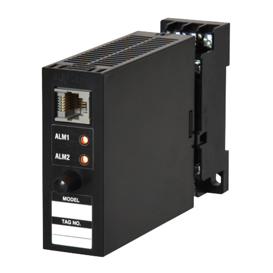
Model VJU7
Universal Temperature
Manual
Converter (Multi-function)
(Isolated Single-output and Isolat-
ed Dual-output Types)
Thank you for purchasing the JUXTA Signal Conditioner.
Please read through this manual before use for correct handling.
CAUTIONARY NOTES FOR SAFE USE OF THE
PRODUCT
This User's Manual should be carefully read before installing and
operating the product. Please keep this User's Manual for future
reference.
For more information of the safety precautions, please refer to the
"Precautions on the Use of the JUXTA Series (IM 77J01A00-91Z1)".
The related manuals and general specifications are shown in the
table below.
Doc. Name
Precautions on the Use of the JUXTA Series (User's Manual) IM 77J01A00-91Z1
Model VJU7 Universal Temperature Converter
(User's Manual)
Model VJU7 Universal Temperature Converter
(General Specifications)
User's manuals in the above table are essential parts of the
product; keep it in a safe place for future reference.
This manual is intended for the following personnel;
•
Engineers responsible for installation, wiring, and maintenance
of the equipment.
•
Personnel responsible for normal daily operation of the
equipment.
The following symbol is used on the product and in this manual to
ensure safe usage.
WARNING
Calls attention to actions or conditions that could
cause serious or fatal injury to the user, and indicates
precautions that should be taken to prevent such
occurrences.
CAUTION
Calls attention to actions or conditions that could
cause injury to the user or damage to the instrument
or property and indicates precautions that should be
taken to prevent such occurrences.
CHECKING THE PRODUCT SPECIFICATIONS
AND THE CONTENTS OF PACKING
(1) Model and Specifications Check
Check that the model and specifications indicated on the
nameplate attached to the side face of the main unit are as
ordered.
(2) Contents of the Package
Check that the package contains the following items:
•
VJU7: 1 unit
Standard Accessories:
•
Tag number label: 1 sheet
•
Range label: 1 sheet
•
RJC sensor (when /RJCN is not specified for the optional
specification): 1
•
User's manual (IM 77J01U07-01E, this manual): 1 copy
•
User's manual (IM 77J01A00-91Z1): 1 copy
IM 77J01U07-01E
10th Edition: Aug. 2020
GENERAL
This plug-in type Universal Temperature Converter receives
thermocouple, RTD or mV signal and converts it into isolated DC
voltage or current signal.
•
•
•
Doc. Number
IM 77J01U07-01E
(This manual)
MODEL AND SUFFIX CODES
GS 77J01U07-01E
Model
VJU7
Fixed
code
Output
configuration
Power supply
Input signal
Output-1 signal
Output-2 signal
Fixed code
Option
*1: Operating range: 85 to 264V AC/DC
*2: Operating range: 12 to 36V DC
*3: DC voltage signal or DC current signal
*4: When option code /C0 or /FB is specified, the conformity to the safety
1.
1
2-9-32, Naka-cho Musashino-shi, Tokyo 180-8750 Japan
You can download the latest manuals from the following website:
http://www.yokogawa.com/ns/juxta/im/
Settings of the input type (thermocouple, RTD or mV) and
measurement range can be changed within the specified ranges.
One of DC voltage signal, DC current signal, communication
function (RS-485) and alarm output (2 relay contacts) can be
selected for the output-2 signal. (Isolated Dual-output Type)
Various parameters such as input range can be set and
modified using a PC (VJ77(sold separately)) or Handy
Terminal (JHT200(sold separately) and the like).
Suffix codes
-0 x
x -U x
x
0 /x
-0
1
2
6
7
-U
A
6
Z
A
6
P
T
N
0
/SN
/C0
/FB
/RJCN
/DF
and EMC standards is excluded. CE marking is not applicable.
MOUNTING METHODS
CAUTION
● Plug/disconnect the main unit into/from the
socket vertically to the socket face. Otherwise the
terminals may bend and it may cause bad contact.
● The converter shall not tilt 5 degrees or more in
either direction when installed.
● When the converter is not connected to the socket,
it is necessary to protect the socket against ingress
of dust to the connector part.
● Keep this product in a conductive bag when
plugged out, during transport or storage.
Description
Universal Temperature
Converter (Multi-function)
Always -0
1 output
2 outputs
100-240 V AC/DC
*1
15-30 V DC
*2
Thermocouple, RTD, mV signal
4 to 20 mA DC
1 to 5 V DC
(Custom order)
*3
4 to 20 mA DC
1 to 5 V DC
Communication function
(RS485)
Alarm output (2 relay contacts)
No output-2
Always 0
No socket (with socket if not
specified)
HumiSeal coating
*4
Fuse bypass
*4
No RJC sensor (with RJC
sensor if not specified)
Fahrenheit display function
Advertisement
Table of Contents

Related Manuals for YOKOGAWA Juxta VJU7


Summary of Contents for YOKOGAWA Juxta VJU7
- Page 1 2-9-32, Naka-cho Musashino-shi, Tokyo 180-8750 Japan You can download the latest manuals from the following website: Thank you for purchasing the JUXTA Signal Conditioner. http://www.yokogawa.com/ns/juxta/im/ Please read through this manual before use for correct handling. IM 77J01U07-01E 10th Edition: Aug. 2020...
-
Page 2: Wall Mounting
flammable or explosive gases or vapors. To do so is 1.1 Wall Mounting highly dangerous. Loosen the main unit-fixing screw to disconnect the main unit ● Use of the product ignoring the specifications may from the socket. Next, anchor the socket onto the wall with cause overheating or damage. -
Page 3: Front Panel
5.1 Settings Related to Input and Output DESCRIPTION OF FRONT PANEL AND CONNECTION OF SETTING OOLS 5.1.1 Input Sensor Type and Input Type Select the input sensor type in [D07: SENSOR TYPE]. Select 4.1 Front Panel TC for thermocouple input, mV for mV input and RTD for The communications connector on the front panel is used for RTD input. -
Page 4: List Of Parameters
An alarm ON delay is a delay time from the establishment of 5.2 Settings Related to Communication alarm conditions to its output; an alarm OFF delay is a delay Function time from the establishment of return-to-normal conditions to Set the following parameters when the communication function is its output. -
Page 5: Maintenance
Output value 2 8.1 Calibration Apparatus ALM1 STATUS Alarm-1 status ALM2 STATUS Alarm-2 status • A voltage and current generator (YOKOGAWA GS200 or the SELF CHK Self-check result equivalent): 1 SET (I/O) Setting (I/O) • 6-dial decade resistance box (YOKOGAWA 279301 or TAG NO.1... -
Page 6: Safety And Emc Standards
SAFETY AND EMC STANDARDS 10. ENVIRONMENT STANDARD The following will be acquired. RoHS Directive: EN 50581 (However, when option code /C0 or /FB is specified, CE mark- Safety: ing is not applicable because the product does not comply IEC/EN 61010-1 compliance (CE) with the Safety and EMC standards.) IEC/EN 61010-2-030 compliance (CE) CAN/CSA-C22.2 No.61010-1 (CSA)
Need help?
Do you have a question about the Juxta VJU7 and is the answer not in the manual?
Questions and answers