Kenwood TK-5210 Instruction Manual
Vhf apco p25 transceiver
Hide thumbs
Also See for TK-5210:
- Service manual (86 pages) ,
- Instruction manual (64 pages) ,
- Modification information (18 pages)

Subscribe to Our Youtube Channel
Related Manuals for Kenwood TK-5210


Summary of Contents for Kenwood TK-5210
- Page 1 INSTRUCTION MANUAL VHF APCO P25 TRANSCEIVER TK-5210 © B62-1796-00 (K) 09 08 07 06 05 04 03 02 01 00...
- Page 2 HANK We are grateful you chose KENWOOD for your land mobile radio applications. We believe this easy-to-use transceiver will provide dependable communications to keep personnel operating at peak efficiency. KENWOOD transceivers incorporate the latest in advanced technology. As a result, we feel strongly that you will be pleased with the quality and features of this product.
- Page 3 One or more of the following statements may be applicable: FCC WARNING This equipment generates or uses radio frequency energy. Changes or modifications to this equipment may cause harmful interference unless the modifications are expressly approved in the instruction manual. The user could lose the authority to operate this equipment if an unauthorized change or modification is made.
- Page 4 For information on Ni-Cd battery recycling in your area, call (toll free) 1-800-8-BATTERY (1-800-822-8837). KENWOOD’s involvement in this program is part of our commitment to preserve our environment and conserve our natural resources. The RBRC Recycle seal found on KENWOOD nickel metal hydride (Ni-MH) battery packs indicates KENWOOD’s voluntary participation in an...
- Page 5 Ensure that there are no metallic items located between the transceiver and the battery pack. • Do not use options not specified by KENWOOD. • If the die-cast chassis or other transceiver part is damaged, do not touch the damaged parts.
- Page 6 If an abnormal odor or smoke is detected coming from the transceiver, switch the transceiver power off immediately, remove the battery pack from the transceiver, and contact your KENWOOD dealer. • Use of the transceiver while you are driving may be against traffic laws.
-
Page 7: Table Of Contents
CONTENTS UNPACKING AND CHECKING EQUIPMENT ......1 ..........1 UPPLIED CCESSORIES PREPARATION ............2 ........... 2 ATTERY RECAUTIONS ....7 NSTALLING EMOVING THE PTIONAL ATTERY ........8 NSTALLING THE PTIONAL NTENNA ..........8 NSTALLING THE ....9 NSTALLING THE AP OVER THE NIVERSAL ONNECTOR .. - Page 8 (CONTENTS CONTINUED…) DTMF (DUAL TONE MULTI FREQUENCY) CALLS ....30 DTMF C (K3 M ) ......30 AKING A ODELS K3 M ) ....... 31 UTODIAL ODELS ............31 EMERGENCY CALLS ..........32 SCRAMBLER (FM)/ ENCRYPTION (APCO) ......33 ........33 ECURE NCRYPTED RANSMISSION...
-
Page 9: Unpacking And Checking Equipment
UNPACKING AND CHECKING EQUIPMENT Note: The following unpacking instructions are for use by your KENWOOD dealer, an authorized KENWOOD service facility, or the factory. Carefully unpack the transceiver. We recommend that you identify the items listed in the following table before discarding the packing material. -
Page 10: Preparation
RECAUTIONS Do not use battery packs or battery chargers not recommended by KENWOOD. ◆ Do not recharge the battery pack if it is already fully charged. Doing so may cause the life of the battery pack to shorten or the battery pack may be damaged. - Page 11 Information concerning the (optional) Li-ion battery pack: The battery pack includes flammable objects such as organic solvent. Mishandling may cause the battery to rupture producing flames or extreme heat, deteriorate, or cause other forms of damage to the battery. Please observe the following prohibitive matters. DANGER •...
- Page 12 • Do not charge the battery near fires or under direct sunlight! If the battery’s protection circuit is damaged, the battery may charge at extreme current (or voltage) and an abnormal chemical reaction may occur. The battery may generate heat or smoke, rupture, or burst into flame.
- Page 13 • Do not reverse-charge or reverse-connect the battery! The battery pack has positive and negative poles. If the battery pack does not smoothly connect with a charger or operating equipment, do not force it; check the polarity of the battery. If the battery pack is reverse-connected to the charger, it will be reverse-charged and an abnormal chemical reaction may occur.
- Page 14 ■ Using the Li-ion Battery Pack • Charge the battery pack before using it. • To keep the battery discharge at a minimum, remove the battery pack from the equipment when it is not in use. Store the battery pack in a cool and dry location. •...
-
Page 15: Installing / Removing The (Optional ) Battery Pack
NSTALLING EMOVING THE PTIONAL ATTERY 1 Match the guides of the battery pack with the corresponding grooves on the upper rear of the transceiver, then firmly press the battery pack to lock it in place. 2 Lock the safety catch to prevent accidentally pressing the release latch and removing the battery pack. -
Page 16: Installing The (Optional ) Antenna
NSTALLING THE PTIONAL NTENNA Screw the antenna into the Optional connector on the top of the antenna transceiver by holding the antenna at its base and turning it clockwise until secure. NSTALLING THE If necessary, attach the belt clip using the two supplied 3 x 8 mm binding screws. -
Page 17: Installing The Cap Over The Universal Connector
NSTALLING THE AP OVER THE NIVERSAL ONNECTOR 1 If you are not using an optional speaker/ microphone or headset, Universal install the cap over the connector cap universal connector. 2 Secure the cap in place using the attached screw. NSTALLING THE PTIONAL PEAKER ICROPHONE OR... -
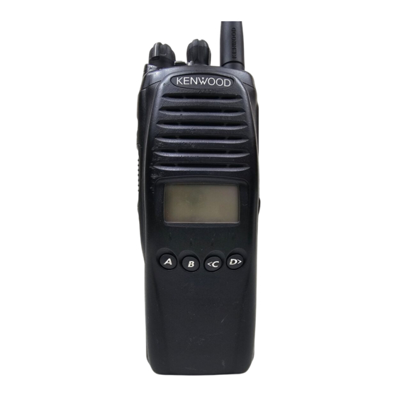
Page 18: Getting Acquainted
GETTING ACQUAINTED Microphone Speaker There are 3 models available: K model: Basic model. K2 model: Equipped with a display and 4-key keypad (A, B, <C, and D>). K3 model: Equipped with a display and full keypad. The above illustration displays the K3 model. - Page 19 q q q q q Power switch/ Volume control Turn clockwise to switch the transceiver ON. Rotate to adjust the volume. Turn counterclockwise fully to switch the transceiver OFF. w w w w w Selector knob Rotate this control to activate its programmable function {page 15}.
- Page 20 !1 !1 !1 !1 !1 Side 2 key Press to activate its programmable function {page 15}. Acts as an Up key for certain transceiver settings. !2 !2 !2 !2 !2 Side 3 key Press to activate its programmable function {page 15}. Acts as a Down key for certain transceiver settings.
-
Page 21: Display
K3 M ISPLAY ODELS y t i . l e P “ ” 1 y t i P “ ” 2 y t i P “ ” P y t i H “ ” I o i t i t c i r r o i t i t c... - Page 22 c i t o i t i t c t i n o i t i t c o i t i t c o i t o i t i t c n i t n i t o i t o i t A, B, C <...
-
Page 23: Programmable Functions
PROGRAMMABLE FUNCTIONS Refer to the following tables to determine which functions are available for appropriate channels. Conventional FM: Channels set up for Conventional FM Operation Conventional APCO: Channels set up for Conventional APCO Operation ✓ : Available • : Mixed Mode only N/A: Not Available i t c... - Page 24 i t c ✓ ✓ ✓ ✓ ✓ ✓ ✓ ✓ ✓ ✓ ✓ • ✓ • ✓ • ✓ ✓ ✓ ✓ ✓ ✓ ✓ ✓ ✓ ✓ ✓ l l a • ✓ l l a • ✓ ✓...
- Page 25 i t c ✓ ✓ ✓ ✓ ✓ ✓ Autodial, Clock, Display Character, Individual, Key Delete, Light, Operator Selectable Tone, OST Down, OST Up, Scan Program, Scrambler/ Encryption Code, Selcall, Selcall Status, Squelch Level, Status, and Talkgroup are available only on K2 and K3 model transceivers.
-
Page 26: Basic Operations
BASIC OPERATIONS ON/ OFF WITCHING OWER Turn the Power switch/ Volume control clockwise to switch the transceiver ON. Turn the Power switch/ Volume control counterclockwise to switch the transceiver OFF. ■ Transceiver Password K2 and K3 model transceivers may be password protected. If the transciever is protected, “INPUT PASSWORD”... -
Page 27: Adjusting The Volume
DJUSTING THE OLUME Rotate the Power switch/ Volume control to adjust the volume. Clockwise increases the volume and counterclockwise decreases it. ELECTING A ONE AND HANNEL Select the desired zone using the selector knob or the keys programmed as Zone Up/ Zone Down. Each zone contains a group of channels Select the desired channel using the selector knob or the keys programmed as Channel Up/ Channel Down. -
Page 28: Transmitting
RANSMITTING 1 Select the desired zone and channel using the selector knob and the Zone Up/ Zone Down or Channel Up/ Channel Down keys. 2 Press the key programmed as Monitor or Squelch Off to check whether or not the channel is free. •... - Page 29 ■ Making Group Calls (APCO) Channels programmed for APCO operation already have a Group ID assigned. For these channels, you do not need to perform steps 1 to 3, below. Otherwise, on K2 and K3 model transceivers, if a key has been programmed with Talkgroup, you can select a group ID from the list to make a call to those parties.
-
Page 30: Receiving
ECEIVING 1 Select the desired zone and channel using the selector knob and the Zone Up/ Zone Down or Channel Up/ Channel Down keys. (If the Scan function has been programmed, you can switch it on or off as desired.) 2 When you hear a caller’s voice, readjust the volume as necessary. -
Page 31: Scan
SCAN Scan is useful for monitoring signals on the transceiver channels. While scanning, the transceiver checks for a signal on each channel and only stops on a channel if a signal is present. To begin scanning, press the key programmed as Scan. •... -
Page 32: Priority Scan
RIORITY A Priority channel must be programmed in order for Priority Scan to function. When using a single Priority channel, the transceiver will automatically change to the Priority channel when a call is received on it, even if a call is being received on a normal channel. -
Page 33: Scan Programming (K2 And K3 Models Only )
K3 M ROGRAMMING ODELS Using the key programmed with Scan Program, you are able to reprogram your scan list. 1 Press the key programmed as Scan Program. • icon appears on the display and blinks. 2 Press the Side 2 and Side 3 keys to select the zone or channel you will add to or remove from the scan list. -
Page 34: Fleetsync: Alphanumeric 2-Way Paging Function
FleetSync: ALPHANUMERIC 2-WAY PAGING FUNCTION FleetSync is an Alphanumeric 2-way Paging Function, and is a protocol owned by KENWOOD Corporation. FleetSync enables a variety of paging functions on your transceiver, some of which depend on dealer programming. Note: This function is available only in Conventional FM Operation. -
Page 35: Status Message
■ Identification Codes An ID code is a combination of a 3-digit Fleet number and a 4-digit ID number. Each transceiver must have its own Fleet and ID number. • Enter a Fleet number (100 ~ 349) to make a group call. •... - Page 36 ■ Transmitting 1 Select your desired zone and channel. 2 Press the key programmed as Status to enter Status mode or Selcall Status to enter Selcall mode. • When using the Status key to enter Status mode, the station ID is fixed and cannot be selected. Skip to step 5 to continue.
-
Page 37: Short Messages
■ Reviewing Messages in the Stack Memory 1 Press and hold the key programmed as Selcall, Status, or Selcall Status for 1 second to enter Stack mode. • The last received message is displayed with the message number. 2 Press the Side 2 and Side 3 keys to select the desired message. -
Page 38: Dtmf (Dual Tone Multi Frequency) Calls
DTMF (DUAL TONE MULTI FREQUENCY) CALLS Note: DTMF calls can be made only in Conventional FM Operation. DTMF C (K3 M AKING A ODELS ■ Manual Dialing 1 Press and hold the PTT switch. 2 Enter the desired digits using the DTMF keypad. •... -
Page 39: Autodial
K3 M UTODIAL ODELS Autodial allows you to quickly call DTMF numbers that have been programmed onto your transceiver. 1 Press the key programmed as Autodial. • The first entry in the Autodial list appears on the display. 2 Press the Side 2 and Side 3 keys or enter the appropriate DTMF number (01 ~ 32) to select your desired Autodial list number. -
Page 40: Emergency Calls
EMERGENCY CALLS If your transceiver has been programmed with the Emergency function, you can make emergency calls. Note: Only the Auxiliary (orange) key and the PF1 (orange) key of the optional speaker/ microphone can be programmed with the Emergency function. 1 Press and hold the key programmed as Emergency. -
Page 41: Scrambler (Fm)/ Encryption (Apco)
SCRAMBLER (FM)/ ENCRYPTION (APCO) Note: ◆ The Scrambler function can be used only in Conventional FM Operation. Additionally, the Voice Scrambler board must be installed before this function can be activated. ◆ Ask your dealer for details concerning the Voice Scrambler board and the Encryption DES/AES settings. -
Page 42: Selecting The Encryption Key
ELECTING THE NCRYPTION 1 Press the key programmed as Scrambler/ Encryption Code (K2 and K3 Models Only) or press and hold the key programmed as Scrambler/ Encryption for 1 second, to enter Key Selection Mode. 2 Select the new Encryption key using the Side 2 and Side 3 keys or the <C and D>... -
Page 43: Signaling
SIGNALING Note: Signaling can be used only in Conventional FM Operation. (QT)/ D (DQT) UIET IGITAL UIET Your dealer may have programmed QT or DQT signaling on your transceiver channels. A QT tone/ DQT code is a sub-audible tone/code which allows you to ignore (not hear) calls from other parties who are using the same channel. -
Page 44: Optional Signaling
After selecting and setting up your desired tone or code, press the Operator Selectable Tone key to activate the OST function. Press this key again to turn the OST function OFF. PTIONAL IGNALING Your dealer may also program several types of option signaling for your transceiver channels. -
Page 45: Voice Operated Transmission (Vox)
VOICE OPERATED TRANSMISSION (VOX) VOX can be activated or deactivated by your dealer. VOX operation allows you to transmit hands-free. This feature can only be used if you are using a supported headset. When operating VOX, you must set a VOX Gain level. This setting allows the transceiver to recognize sound levels. -
Page 46: Vox Operation
VOX O PERATION 1 Connect the headset to the transceiver. • The VOX function does not activate when a headset is not connected to the accessory terminal of the transceiver. 2 Press and hold the key programmed as VOX for 2 seconds. -
Page 47: Clock (K2 And K3 Models Only)
CLOCK (K2 and K3 Models Only) If activated by your dealer, your transceiver can track the time with its built-in clock. The time will display momentarily when the transceiver power is turned ON. Additionally, you can view the clock any time by pressing the key programmed as Clock. -
Page 48: Advanced Operations
ADVANCED OPERATIONS Your transceiver operations vary according to the functions that your dealer has programmed onto the transceiver keys. Following is brief overview of the programmable functions. Refer to those functions which have been programmed onto your transceiver. • Autodial (AD) Press this key to quickly call a DTMF number that has been pre-stored in your transceiver memory. - Page 49 • Channel Select Using the selector, turn clockwise to increase the channel number and counterclockwise to decrease the channel number. If a channel has not been programmed, an error tone will sound. • Channel Up (CH▲) Press this key to increase the channel number. Press and hold this key to cycle up through the channel numbers.
- Page 50 • External Speaker (ESP) Press this key to switch the speaker from the transceiver’s built-in speaker to an optional external speaker. When pressed, all messages and tones will sound from the optional external speaker that is attached to the transceiver, rather than from the transceiver’s built-in speaker.
- Page 51 • Key Lock (LCK) Press and hold this key for 1 second to lock the transceiver keys. When activated, the front panel keypad and the programmable function keys (other than those listed below) can no longer be used and “LOCKED” appears on the display.
-
Page 52: Quiet Talk (Dqt)"
Channels programmed with low power cannot be switched to high power, but channels programmed with high power can be switched to low power and then back to high power by pressing this key again. When using high power, the icon appears on the display. •... - Page 53 • OST Up (OS▲) Press this key to increase the Operator Selectable Tone number of your selected channel. (This key functions similar to the Operator Selectable Tone key.) • Scan (SCN) Press this key to scan your transceiver channels for a signal.
- Page 54 • Selcall (SEL) Press this key to enter Selcall mode. Press and hold this key to enter Stack mode. Refer to “FleetSync: ALPHANUMERIC 2-WAY PAGING SYSTEM” on page 26 for details. • Selcall Status (SES) Press this key to enter Selcall mode. Press and hold this key to enter Stack mode.
- Page 55 • Status (STS) Press this key to enter Status mode. Press and hold this key to enter Stack mode. Refer to “FleetSync: ALPHANUMERIC 2-WAY PAGING SYSTEM” on page 26 for details. • Tactical Group (TAC) Press and hold this key for 1 second to register the selected channel as a Tactical Group channel.
- Page 56 Press and hold the VOX key for 2 seconds to turn VOX Operation mode ON or OFF. Refer to “VOICE OPERATED TRANSMISSION (VOX)” on page 37 for details. • Zone Down (ZN▼) Press this key to decrease the zone number. Press and hold this key to cycle down through the zone numbers.
-
Page 57: Background Operations
BACKGROUND OPERATIONS Your dealer can activate a variety of transceiver functions to perform without any additional operation on your part. (TOT) IMER The Time-out Timer is used to prevent any caller from using a channel for an extended period of time. If you continuously transmit for a period of time that exceeds the programmed time, the transceiver will stop transmitting and an alert tone will sound. -
Page 58: Low Battery Warning
ATTERY ARNING Low Battery Warning alerts you when the battery needs to be recharged. On all transceivers, your dealer can set an alert tone to sound and the LED indicator to blink red when the battery power is low. On K2 and K3 model transceivers, the battery power icon displays the battery power remaining, as illustrated below. -
Page 59: Ptt Id
PTT ID PTT ID is the transceiver unique ID code which sent each time the PTT switch is pressed. Note: PTT ID can be made only in FM Operation. If Beginning of Transmit is set, the ID signal is transmitted when you press the PTT switch.
Need help?
Do you have a question about the TK-5210 and is the answer not in the manual?
Questions and answers