DMP Electronics 1134 Installation And Programming Manual
Wireless access control module
Hide thumbs
Also See for 1134:
- Installation and programming manual (36 pages) ,
- Installation and programming manual (44 pages)
Table of Contents
Advertisement
Quick Links
Advertisement
Table of Contents

Related Manuals for DMP Electronics 1134


Summary of Contents for DMP Electronics 1134
- Page 1 1134 Wireless Access Control Module INSTALLATION AND PROGRAMMING GUIDE...
-
Page 3: Table Of Contents
TABLE OF CONTENTS About the 1134 ..........1 Install the 333 Suppressor ....... 11 Wire the Zone Terminals ........12 Power Supply ............1 Connect a Wiegand Card Reader ....14 Zone Terminals ............1 Connect the Power Supply ......17 Annunciators ............ - Page 4 Certifications ..........32 Product Specifications ......33 Readers and Credentials ......34 FCC Information ........36 Industry Canada Information ....37 Compatibility ..........38...
-
Page 5: About The 1134
ABOUT THE 1134 The 1134 Wireless Access Control Module allows you to use the powerful, built in access control capability of DMP Panels using smartcard, proximity, mag stripe, or biometric readers, or other compatible authentication devices. The 1134 includes the following... -
Page 6: Form C Relay
DMP LCD keypad for initial setup. Programming can be completed using a keypad connected to the 1134 or from XR150/XR550 Series panels. Dry/Wet Contact Apply 12 VDC power from the module... -
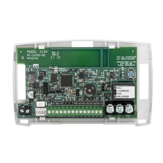
Page 7: Pcb Features
Tamper Survey Reset RELAY Button Keypad Dry/Wet Programming Contact RESET TAMPER Header DISABLE RED WHTGRN BLK PROG Power Wiegand Status Zones Door Supply Inputs Indicator Relay Outputs Terminal Figure 1: PCB Features Digital Monitoring Products, Inc. 1134 Installation and Programming Guide... -
Page 8: Program The 1134
(XR150/XR550 only) Select WLS at COMM TYPE and press CMD. Note: Panel version 191 or higher software is required. Enter the eight-digit SERIAL# that starts with 14 (SN1) and press CMD. Enter the SUPRVSN TIME and press CMD. 1134 Installation and Programming Guide Digital Monitoring Products, Inc. -
Page 9: Zone Information
Additional zones must be entered sequentially. See Table 1. Panel Zones XT30/XT50, The zone numbers begin with the 1134 address and are followed by the particular XTLplus, zone from the 1134. For example, an 1134 at keypad address 4 would provide & XTLtouch zones 41, 42, 43, and 44. -
Page 10: Install The 1134
Relocate the transmitter or receiver until the LED confirms clear communication. 1134 Installation and Programming Guide Digital Monitoring Products, Inc. -
Page 11: Mount The 1134
The module comes in a high-impact plastic housing that you can mount directly to a wall, backboard, or other flat surface. For easy installation, the back and ends of the 1134 housing have wire entrances. The back also contains multiple mounting holes that allow you to mount the module on a single-gang switch box. -
Page 12: Wire The Access Control Lock
Refer to “Isolation Relay (optional)” for more information. When the jumper on the 1134 is set to WET, up to 750 mA 12 VDC will pass though the C terminal and no additional power supply is needed. - Page 13 Suppressor Model 333 DC Door Strike Suppressor Door strike negative to Door strike negative to power supply negative module DC negative Figure 5: Wet Door Strike Wiring Figure 4: Dry Door Strike Wiring Digital Monitoring Products, Inc. 1134 Installation and Programming Guide...
-
Page 14: Isolation Relay (Optional)
Isolation Relay Power 12/24 VDC – Model 333 Magnetic Lock Supply Power Model 333 Suppressor – Supply Suppressor Figure 7: Door Strike with Figure 6: Magnetic Lock with an Isolation Relay an Isolation Relay 1134 Installation and Programming Guide Digital Monitoring Products, Inc. -
Page 15: Install The 333 Suppressor
Install the 333 Suppressor Use the included 333 suppressor with the 1134 to suppress any surges caused by energizing a magnetic lock or door strike. Install the 333 across the module’s C (common) and NO (normally open) or NC (normally closed) terminals. -
Page 16: Wire The Zone Terminals
Use the supplied 311 1k Ohm End-of-Line (EOL) resistors on each zone. Refer to the panel programming guide for programming instructions. See Table 2 and Figure 9 for more information on wiring the zone terminals. 1134 Installation and Programming Guide Digital Monitoring Products, Inc. - Page 17 Table 2: 1134 Zone Uses Zone 1 Zone 3 can also be wired normally Zone 2 closed with an Zone 3 in‑line 1k Ohm resistor Zone 4 RED WHTGRN BLK Figure 9: Zone Terminal Wiring Digital Monitoring Products, Inc. 1134 Installation and Programming Guide...
-
Page 18: Connect A Wiegand Card Reader
Connect a Wiegand Card Reader The 1134 provides direct 12/24 VDC, 200 mA output to the reader on the Red terminal connection. Figure 10 shows a reader with wire colors RED, WHT, GRN, and BLK connecting to Terminals 1, 2, 3, and 4. - Page 19 ALL SYSTEM ON. Connect a wire from the AS Terminal to an armed status indicator. Caution: Status indicator outputs support a maximum of 100 mA per terminal. Exceeding the maximum rating on LC, RA, or AS terminals can damage equipment. Digital Monitoring Products, Inc. 1134 Installation and Programming Guide...
- Page 20 Wiegand Card Reader Yellow Orange or Brown Black (GND) Green (Data 0) White (Data 1) Red (12/24VDC) RED WHTGRN BLK Figure 10: Wiegand Card Reader Wiring 1134 Installation and Programming Guide Digital Monitoring Products, Inc.
-
Page 21: Connect The Power Supply
Use 22 AWG wire to connect the DC power terminal block on the device to the DC power terminal on the 505-12 power supply PCB. Connect the transformer to an unswitched 120 VAC 1.5 Amp power source. Digital Monitoring Products, Inc. 1134 Installation and Programming Guide... -
Page 22: Program The 1134
1134 from the panel, all future programming should be performed through the panel. The panel’s programming overrides any programming performed from a keypad connected to the 1134. While the 1134 is in programming mode, it will not be able to communicate with the panel. -
Page 23: Programmer Menu
Press CMD to advance to Initialization Options. Serial Number Dispay SERIAL#: XXXXXXXX View the serial numbers for the 1134. The 1134 has a Type 14 and Type 08 serial number. Press CMD to view the second serial number. INITIALIZATION OPTIONS INITIALIZE ALL? These options can set the 1134 module programming... -
Page 24: Access Options
Selecting NO allows standard zone operation on zone 2. The default is NO. If the door being released by the 1134 module is protected (contact installed), a programmable bypass entry/exit timer can be provided by connecting its contact wiring to module zone 2. - Page 25 Selecting NO leaves the relay on when zone 2 changes state. Turning off the relay allows a long strike time to be automatically ended upon zone 2 change and relocks the door. The default is NO. Digital Monitoring Products, Inc. 1134 Installation and Programming Guide...
-
Page 26: Activate Zone 3 Request To Exit
Activate Bypass Only Wire zone 3 as normally closed with an in-line 1k Ohm resistor. When zone 3 opens from a normal state, only a bypass occurs and the onboard relay does not activate. 1134 Installation and Programming Guide Digital Monitoring Products, Inc. -
Page 27: Activate Onboard Speaker
The door strike relay is activated for the length of time programmed in ZN 3 REX TIME. No user code information is sent to the panel. The menu advances to “No Communication with Panel”. The default card format is DMP. Digital Monitoring Products, Inc. 1134 Installation and Programming Guide... - Page 28 2-8. See “Public Card Formats” for some publicly available card formats that can be used with the 1134. Other private or custom formats may also be compatible. Please contact the credential supplier or manufacturer for the bit structure.
- Page 29 Position = 1 Position = 9 Received Received Length = 8 Length = 16 Position = 25 Position = 0 Example: Wiegand Code Length = 26 bits Figure 12: Wiegand Data Stream Bit Location Digital Monitoring Products, Inc. 1134 Installation and Programming Guide...
- Page 30 0-255. Press CMD to save. Default is 9. Press select area 4 to clear the user code length and enter a number between 16-64. Press CMD to save. Default is 16. 1134 Installation and Programming Guide Digital Monitoring Products, Inc.
-
Page 31: Require Site Code
In the keypad display, enter site code 1 and press CMD. The display will ask for site code 2 followed by site code 3 and so on. When you have selected the site code you want to change, press CMD. Digital Monitoring Products, Inc. 1134 Installation and Programming Guide... -
Page 32: Number Of User Code Digits
Number of User Code Digits NO OF USER CODE The 1134 module recognizes user codes from 4-12 digits long. DIGITS: Press any top row select key or area to enter a user code digit length. This number must match the user code number length being programmed in the panel. -
Page 33: No Communication With Panel
Press CMD to display additional actions. Press the first LAST select key or area to choose LAST (Keep Last State). The relay remains in the same state and does not change when communication is lost. Digital Monitoring Products, Inc. 1134 Installation and Programming Guide... -
Page 34: Remove Keypad
After five seconds, the piezo begins sounding continually. To disconnect the keypad and silence the piezo, remove the keypad harness. 1134 Installation and Programming Guide Digital Monitoring Products, Inc. -
Page 35: Public Card Formats
Code Position Length Position Length Digits Length H10301 26 bit H10302 37 bit w/o FAC H10304 37 bit w/ FAC Farpointe 39 bit Corporate 1000 35 bit Corporate 1000 48 bit Digital Monitoring Products, Inc. 1134 Installation and Programming Guide... -
Page 36: Certifications
CERTIFICATIONS FCC ID: CCKPC0205 Industry Canada ID: 5251A-PC0205 1134 Installation and Programming Guide Digital Monitoring Products, Inc. -
Page 37: Product Specifications
230 mA (includes 200 mA for proximity reader) Reader Current up to 200 mA Zones 5 VDC, 2 mA max Total Available Output Current 750 mA Dimensions 4.5 W x 2.75 H x 1.75 D in 11.43 W x 7 H x 4.45 D cm Weight 8 oz 0.23 kg Digital Monitoring Products, Inc. 1134 Installation and Programming Guide... -
Page 38: Readers And Credentials
ProxKey III® access device ProxPoint Plus® proximity PP-6005B 1351 ProxPass® reader ProxPro® proximity reader with PR-5355 1386 ISOProx II® card keypad PR-5455 ProxPro® II proximity reader TL-5395 Thinline II® proximity reader 1134 Installation and Programming Guide Digital Monitoring Products, Inc. - Page 39 Delta5* Single gang box mount CSK-2 MIFARE® DESFire® EV2 keyfob smartcard reader smartcard Delta6.4* Smartcard reader with keypad CSR-35P Bluetooth smartcard reader *Delta Proximity Readers and Credentials not evaluated by UL. Digital Monitoring Products, Inc. 1134 Installation and Programming Guide...
-
Page 40: Fcc Information
Increase the separation between the equipment and receiver. • Connect the equipment into an outlet on a circuit different from that to which the receiver is connected. • Consult the dealer or an experienced radio/TV technician for help. 1134 Installation and Programming Guide Digital Monitoring Products, Inc. -
Page 41: Industry Canada Information
L’exploitation est autorisée aux deux conditions suivantes: l’appareil ne doit pas produire de brouillage, et l’utilisateur de l’appareil doit accepter tout brouillage radioélectrique subi, même si le brouillage est susceptible d’en compromettre le fonctionnement. Digital Monitoring Products, Inc. 1134 Installation and Programming Guide... -
Page 42: Compatibility
Note: If the 3rd digit of the transmitter’s serial number is greater than 0, it will be v106 or higher. If the 3rd digit is equal to zero, that transmitter must be removed or replaced with a newer transmitter for the 1134 to function properly. - Page 44 LT-1889 20314 © 2020 Digital Monitoring Products, Inc.
Need help?
Do you have a question about the 1134 and is the answer not in the manual?
Questions and answers