Table of Contents
Advertisement
Quick Links
Advertisement
Table of Contents

Related Manuals for AUDAC R2


Summary of Contents for AUDAC R2
- Page 1 User Manual www.audac.eu...
-
Page 3: Table Of Contents
Rear description Audio in- and outputs Priority & Fiber link inputs Peripheral interfaces Control ports & Power inlet Chapter 3: R2 Quick Start Guide Connecting the R2 Configuring the R2 Chapter 4: User interface & configuration Open the user interface... - Page 4 Chapter 5: Peripheral interfaces Wall mounted control panels DW3020/4020 Basic wall panel DW5066 All-in-one wall panel Connection possibilities Chapter 6: Paging Chapter 7: Cascading the R2 Principle Fiber audio flow Setting up the project Chapter 8: Additional information IP Basics...
-
Page 5: Introduction
Every R2 is standard equipped with an integrated Ethernet control interface which makes it possible to configure and control the R2 from any PC, laptop or PDA which is connected to the internet. Just use your browser, go to the appropriate website and you have complete control of the R2. -
Page 6: Precautions
Precautions READ FOLLOWING INSTRUCTIONS FOR YOUR OWN SAFETY ALWAYS KEEP THESE INSTRUCTIONS. NEVER THROW THEM AWAY ALWAYS HANDLE THIS UNIT WITH CARE HEED ALL WARNINGS FOLLOW ALL INSTRUCTIONS NEVER EXPOSE THIS EQUIPMENT TO RAIN, MOISTURE, ANY DRIPPING OR SPLASHING LIQUID. AND NEVER PLACE AN OBJECT FILLED WITH LIQUID ON TOP OF THIS DEVICE. DO NOT INSTALL THIS UNIT NEAR ANY HEAT SOURCES SUCH AS RADIATORS OR OTHER APPARATUS THAT PRODUCE HEAT DO NOT PLACE THIS UNIT IN ENVIRONMENTS WHICH CONTAIN HIGH LEVELS OF DUST,... -
Page 7: Additional Information
This manual is put together with much care and effort and is as complete as could be on the publication date. However, updates on the specifications, functionality or software may have occurred since publication. To obtain the latest version of both manual and software, please visit the Audac website @ www.audac.eu. -
Page 9: Chapter 1: Connections And Connectors
Chapter 1 Connections and connectors CONNECTION STANDARDS The in- and output connections for AUDAC audio equipment are performed corresponding to international wiring standards for professional audio equipment. Cinch (RCA): For unbalanced line input connections Tip: Signal Sleeve: Ground White: Left... - Page 10 For unbalanced line in, output & priority connections: RJ45 (RS485, Digital audio, +24V DC): For connection to Wall Panels & Paging Consoles Pin 1 White-Orange AUDIO TX A Pin 2 Orange AUDIO TX B Pin 3 White-Green +24V DC Pin 4 Blue RS485 A Pin 5...
-
Page 11: Wire Up The System
The M2 has RS232, RS485 and TCP/IP ports which all accept the same commands. The complete command set to control the M2 is available in the M2 commands user manual which is freely downloadable on www.audac.eu Wire up the system The wiring of the system must be done according to the following rules, to guarantee proper functioning of the system in all circumstances. -
Page 12: Chapter 2: Overview Front And Rear Panel
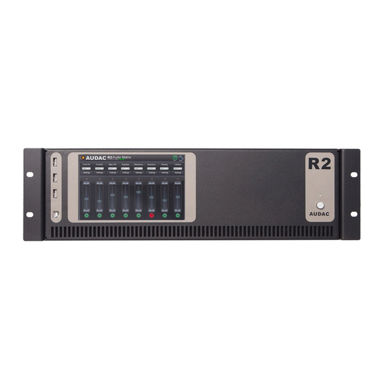
Overview front & rear panel Front On the front of the R2 amplifier is a power button, One USB (A) connection for updating an optional touchscreen (R2DIS) provided. The power button is a latching type and should be used for powering-up the system. -
Page 13: Audio In- And Outputs
The link in- and outputs are optical fiber connectors which can be used for cascading multiple R2’s. For this feature, the optional fiber interconnection module (OPT2) has to be installed. -
Page 14: Peripheral Interfaces
A 24 Volts emergency power supply can be connected to this 2-pin Terminal block connector for keeping the R2 running on emergency power when the mains power is shut down. When the R2 is running on 24 Volt emergency power, the function of the power switch on the front panel is bypassed and can’t switch the R2 off. -
Page 15: Chapter 3: R2 Quick Start Guide
Chapter 3 R2 Quick start guide This chapter guides you through the setup process of a basic project with one R2 audio matrix and 8 standard DW3020/4020 wall panels. Wall panels Audio sources Prog. Prog. Prog. Prog. Prog. Prog. Prog. -
Page 16: Configuring The R2
The default administrator password (gives you access to all functions) is “R2” and the default user password (gives you only access to the basic functions) is “user”. If you want to make any changes to the settings, you should log-in with the administrator password. - Page 17 window (Standard are line inputs 1 to 8 selected). Simply select the desired input signals by the dropdown lists on the corresponding location. After the desired input channels are selected, click the “Set inputs” button to save the changes. The selected inputs are now selectable in the “Quick menu”...
-
Page 18: Chapter 4: User Interface & Configuration
Connect the R2 to your network using a straight cable, it is recommended that the port connected to the Audac R2 is set to a speed of 10/100MB. Ensure that the computer being used to control the R2 is within the same range and the default IP address for the R2 192.168.0. -
Page 19: Main Screen
Main screen The main screen displays all 8 output zones of the R2 with fader volume controls. Volume control The volume of each channel can be set by moving the fader of the corresponding channel up or down. At the top and bottom side of each fader is a button with an arrow displayed whereby the volume can be raised or lowered in steps of 1 dB. -
Page 20: Zone Settings
These are all additional input signals (Line or Microphone) which are connected to an optional wall input unit (DW5066) inputs on the rear side of the R2. In the third table are the “Fiber Inputs” displayed (Only functional when the optional OPT2 module is installed). - Page 21 To make sure the changed zone settings are still effective after shutdown and restart of the R2, the “Save” button on the main screen of the R2 need to be pressed. At the same time, the volume and routing settings will be saved.
-
Page 22: Sound Settings
Zone settings >> Sound settings The “Sound Settings” window offers the possibility to apply a digital filter to the selected output zone, and to adjust the sound settings by means of the two-band tone control. Digital Filter To apply a filter to the selected output zone, tick the “Enable Filter” checkbox and select the desired filter type between High-Pass, Low-Pass and Band-Pass. -
Page 23: Test Signals
The test signals window gives an overview of all special input signals which can be patched to the selected output zone. The R2 has an internal digital signal generator which can generate white noise, pink noise and sinusoidal signals with a selectable frequency. -
Page 24: Zone Linking
R2. The linking between the zones will remain as long as the contact is established. For example, this can be done by means of a switch or relay. -
Page 25: Input Selection
Zone settings >> Input selection The “Input Selection” window allows you to make a selection out of all available input signals for the “Quick Selection Menu”. This is displayed on the main screen just below the zone name. It is convenient to add the 8 common used and most important input signals to the “Quick Selection Menu”. -
Page 26: Configuration Settings Screen
The configuration settings control panel comes up after clicking the “Setup” button. (Only on Administrator level) In this window, all the settings of the R2 can be made, such as selecting the desired digital input source, changing the time settings, configuring the built-in timer, adjusting the network... -
Page 27: Timer Settings
Settings >> Timer Settings Up to 256 pre-programmed timer presets can be made in the “Timer Settings” window. Signal routing, output volume, muting & paging volume can all be selected t at pre- programmed moments. The action which needs to be performed should be selected by means of the “ACTION”... -
Page 28: Time Settings
Timer settings Settings >> Time settings The actual time and date of the R2 can be set in this window. This can be done on two different ways, the clock settings can be made manually by selecting the right values from a dropdown list, or when connected to the internet, the current time and date can be retrieved from a time server. -
Page 29: Network Settings
Settings >> Network settings In this window, the network settings of the R2 can be adjusted. The IP address is standard set to 192.168.0.191 and the subnetmask is standard set to 255.255.255.0. Click the “OK” button to confirm the network settings. -
Page 30: Priority Settings
Priority 1 to Priority 4. The input selected for Priority 1 has the highest level of priority, the input selected for priority 4 has the lowest. Note: On all Audac devices, priority settings always have priority over paging. Priority input selection You can select the desired priority channel by clicking on the corresponding button on top of the window, and switching them on and off can be done by clicking the “Enabled”... -
Page 31: System Configuration
When the priority situation is over (no more signal present on the priority audio inputs or no more connection between the priority input contacts), the status of the R2 will return to the previous status by fading the sound in. Click the “OK” button to confirm the priority settings. -
Page 32: R2 Address Settings
System configuration Settings >> R2 Address settings In this menu, the address of the R2 can be set. This address is factory default set on “001” and is selectable between “001” and “099”. When only one R2 is available, the default address can be left to its default value. -
Page 33: Fiber Settings
Address Settings Settings >> Fiber settings In this window can be set which audio signals of the R2 should be transmitted over the fiber interconnection interface. NOTE The fiber interconnection interface is an optional module for the R2. (OPT2) The settings which are made in this window will only affect when the internal fiber interconnection interface of the R2 is installed. -
Page 34: Amplifier Bridging
Just click on the button corresponding with the zone,will set the output of that zone to mono. which you can then bridge the output on the back side on the R2, the amplified Left and Right output channels, become of 120Watt @ 8 ohm. -
Page 35: Password Settings
Amplifier Bridging Settings >> Password settings In this window the passwords for the R2 can be changed. There are two different password levels. Administrator level which has full access to all functions and User level, which has only access to the basic functions. -
Page 36: Factory Settings
R2 Password Settings Settings >> Factory settings ATTENTION BE CAREFUL to press this button. It really will recall the ORIGINAL factory settings !!! It does not recall the previously saved settings, but it recalls the original factory setting and the previously made settings will be lost. -
Page 37: Chapter 5: Peripheral Interfaces
PI port on the rear side of the R2. As this already suggests, there are 10 PI ports available on the rear side of the R2, each of them performed with an RJ45 connector. 8 of these PI ports are capable of transporting bidirectional audio and data (ports PI 1-8), while the remaining two ports are only capable of transporting data (ports PI 9-10). -
Page 38: Wall Mounted Control Panels
UTP/FTP CAT6 cable or better. Wall mounted control panels The R2 installation can be expanded with additional wall control panels. There are two kinds of wall panels available, one standard wall panel (DW3020/4020) which allows to adjust the... -
Page 39: Dw3020/4020 Basic Wall Panel
The DW3020/4020 is the basic wall panel which allows to control the routing and the volume of the R2. A selection out of up to 8 input signals can be made by means of the DW3020/4020 wall panel. The inputs which are selectable by means of the wall panel can be configured in the user interface under ‘Zone settings’... -
Page 40: Dw5066 All-In-One Wall Panel
The DW5066 wall panel should be connected to the R2 by means of a UTP/FTP Cat6 (or better) cable. First read the PI connection principles in the beginning of this chapter before making any connections. - Page 41 be removed again from this listbox by selecting them, and clicking the “Remove Input” button. A maximum of 24 signal inputs can be selected. The inputs which are selected in this listbox, are available for all zones which can be controlled by this DW5066 wall panel. Those inputs are not linked with the quick menu like the inputs on the DW3020/4020 are.
-
Page 42: Connection Possibilities
Prog. Multiple DW3020/4020 Wall panels on one PI Port (PI1 to PI10) Prog. Prog. LINE IN MIC IN AUDAC Prog. Prog. LINE IN MIC IN AUDAC Multiple DW3020/4020 and one DW5066 Wall panel on one PI Port (PI1 to PI8) -
Page 43: Chapter 6: Paging
Paging 1 Zone paging example The most basic example of an R2 paging system is an R2 audio matrix, in combination with an APM101MK2 paging console. This setup makes it possible to announce messages in 1 or more pre-defined zones, and with a pre-defined volume for every zone. - Page 44 ARJ03P 2) Separate PI input Multiple APM’s can be connected to the R2, each of them using a separate PI Input. If the selected paging zones are different, paging to different zones can be done at the same time. If multiple APM’s are trying to page to the same zone at the same time, then paging is priority based, and only the message coming from the APM with the highest priority (lowest address) will be announced.
- Page 45 APM should be connected to the R2, and the configuration should be done through the web based user interface of the R2 or via the Audac system manager. You can find the paging configuration settings in the “Setup” menu, under “System configuration”, and “Paging”.
- Page 46 list, the peripheral port on which the APM is connected can be selected, ranging from RS485(1) to RS485(8). When APM108MK2 or APM116MK2 are connected, the number of layers for your APM configuration can be determined by means of the dropdown list on the right side of this window.
- Page 47 “Add”’ button. Zones can be removed from this listbox by selecting them, and clicking the “Remove” button. Up to 40 zones, from 5 cascaded R2’s can be programmed under one button. Play message: By means of this function, messages stored in the APM memory, such as emergency or commercial announcements can be announced.
-
Page 48: Chapter 7: Cascading The R2
The output of the second R2 should be connected with the input of the third R2, and so on. At the end, the output of the last R2 has to be connected with the input of the first R2. This way, a ring is closed and the network is completed. -
Page 49: Fiber Audio Flow
Fiber audio flow The diagram shown below shows an audio flow of an example project with 5 R2’s cascaded through the fiber interconnection interface where every R2 has an address going from “R001” to “R005”. Next to every R2 are shown which signals are received and transmitted over the fiber, while next to the connection line is shown which signals the fiber is carrying at this point. - Page 50 Diagram explanation Every R2 is indicated with a different colour, and next to every R2 is a table shown with 8 incoming fiber audio channels and 8 outgoing fiber audio channels. Between two devices, a connection line is shown representing the fiber conductor, and next to this connection line is always a table shown which indicates the audio channels the fiber conductor is carrying at this point.
-
Page 51: Setting Up The Project
To configure your system according to Method 1, proceed with the following procedure: Connect the first R2 of your setup to your Ethernet network Set the address for the first R2 to “R001”, this can be done in the “Setup” menu, under “R2 Address Settings”. - Page 52 Ethernet 192.168.0.193 R004 R004 Ethernet 192.168.0.194 R005 R005 Ethernet 192.168.0.194 Example setup with 5 R2’s, on the left side with only one Ethernet connection (Method 1) while on the right side every R2 has a separate ethernet connection (Method 2)
- Page 53 “Fb 7”. For all the other fiber channels, “R001” just send the incoming data to the next R2. So a source signal should be selected for fiber channels “Fb 4” and “Fb 7”. All signals available on the R2 can be selected by means of the dropdown list.
- Page 54 5) Connecting wallpanels Connect all your wallpanels to the Peripheral inputs on the rear of the R2. A detailed description about connecting wallpanels is extensively described in an earlier chapter of this user manual. 6) Ready Your project is now ready for use.
-
Page 55: Chapter 8: Additional Information
IP range of AUDAC products is “192.168.000.xxx”. If your network is using a different IP range, the AUDAC products will not be accessible from your network. You can change the IP address of the AUDAC products to make them work properly in... -
Page 56: Updating The R2
The easiest way to keep your R2 device up to date is through the Audac System Manager. The Audac System manager (ASM) is a windows compatible software application which detects all ‘smart’... -
Page 57: Technical Specifications
Type 8 x Stereo Unbalanced Line Connector Control possibilities RS232 Wall Panels (RS485) Smart devices (Audac Touch) TCP/IP (Integrated webserver) Front panel (Optional touchscreen) Power supply Mains power 100 ~ 240 V AC / 50 ~ 60 Hz Emergency power... -
Page 58: Personal Notes
Notes... - Page 59 Notes...
- Page 60 Notes...
Need help?
Do you have a question about the R2 and is the answer not in the manual?
Questions and answers