Page 1
Instructions for use
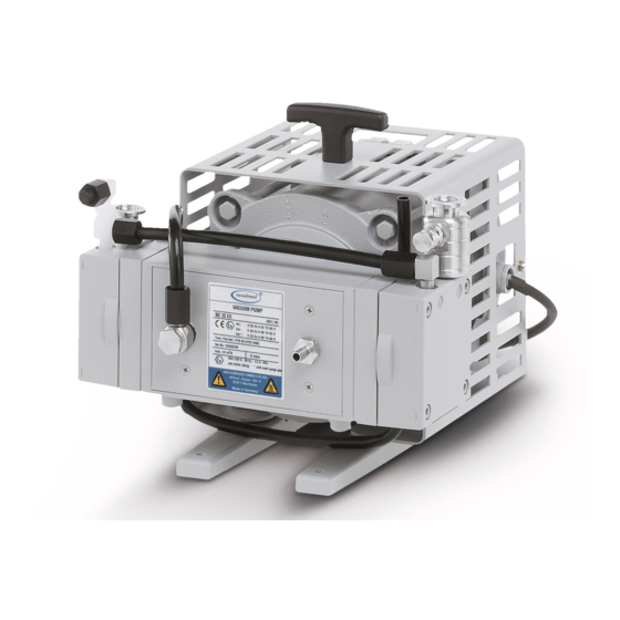
 MZ 2C EX MD 4C EX MV 10C EX MZ 2C EX + AK + EK MZ 2C EX + IK + EK MD 4C EX + AK + EK MV 10C EX + AK + EK...
Page 2
2 of 75 Dear customer, Your VACUUBRAND diaphragm pump shall support you at your work for a long time without any trouble and with full load output. Thanks to our large practical experience we attained much information how you could add to an efficient application and to personal safety.
Page 3
page 3 of 75 Documents are only to be used and distributed completely and unchanged. It is strictly the users´ responsibility to check carefully the validity of this document with respect to his product. manual-no.: 999128 / 29/04/2014...
Page 4
page 4 of 75 Documents are only to be used and distributed completely and unchanged. It is strictly the users´ responsibility to check carefully the validity of this document with respect to his product. manual-no.: 999128 / 29/04/2014...
page 5 of 75 Contents Safety information! .....................6 General information ..........................6 Intended use ............................6 Setting up and installing the equipment .....................6 Ambient conditions ...........................10 Operating conditions ........................10 Safety during operation ........................12 Maintenance and repair ........................13 Notes regarding devices with ATEX conformity ............14 Technical data ......................16 Wetted parts ............................18 Pump parts ............................18...
page 6 of 75 Safety information! General information ☞ Read and comply with this manual before installing or operating the equip- NOTICE ment. ☞ Transport the pump at the provided handle. Remove all packing material, remove the product from its packing-box, remove the protective covers from the inlet and outlet ports and keep, inspect the equipment.
Page 7
page 7 of 75 The inner (pumped media) and outer part of the pump have to be evaluated separately because of their different conformity (see also section ”Technical data” and ”Notes regarding devices with ATEX conformity”). The pumps are not suitable for pumping dust and have no approval for operation below ground.
Page 8
page 8 of 75 Inlet ☞ Connection lines at the pump inlet have to be performed conductive grounded and gas tight (designation of the pump connections see figures). ☞ The diameter of the inlet pipeline should be at the least as large as the diameter of the pump connection pipelines.
Page 9
page 9 of 75 Inert gas purge ☞ The user must take suitable precautions to prevent any formation of explosive mixtures in the expansion chamber using inert gas to purge the housing. Other- wise in case of a diaphragm crack, mechanically generated sparks, hot surfaces or static electricity may ignite these mixtures.
page 10 of 75 Attention: Never use the antistatic connection at the housing of the device to connect the device to ground, use only the green or green and yellow connection wire of the motor. Use the antistatic connection at the housing only to perform an antistatic connection of other non-electronic devices and components, e.
Page 11
page 11 of 75 ☞ Adopt suitable measures to prevent the release of dangerous, explosive, corro- sive or polluting fluids. ☞ If pumping different substances, it is recommended to purge the pump with air or inert gas prior to changing the pumped media in order to pump out residues and to avoid reactions of the pumped substances with each other and with the pump materials.
page 12 of 75 Safety during operation ➨ Adopt suitable measures to prevent the release of dangerous, toxic, explosive, corrosive, noxious or polluting fluids, vapours and gases. In case install an ap- propriate collecting and disposal system and take protective action for pump and environment.
page 13 of 75 Maintenance and repair Wear parts have to be replaced regularly. In normal use, the lifetime of the dia- phragms and valves is typically 15,000 operating hours. Bearings have a typical du- rability of 40000 h. • The motor capacitors have to be replaced after 200000 start/stop cycles at the latest.
The equipment used has to comply with these requirements. VACUUBRAND does not advise customers concerning requirements to the equipment under the specific aspects of the cus- tomers applications.
Page 15
15 of 75 Electrical connection: VACUUBRAND diaphragm pumps with ATEX-conformity are equipped with a 230 V / 50 Hz single- phase motor and are protected by a thermal cutout with manual reset combined with an overcurrent protection. See instructions for use concerning notes on electrical connection Where applicable the motors can be connected directly to an appropriate power supply by suitably trained and authorised personnel (electrician).
page 18 of 75 Wetted parts Components Wetted parts Inlet stainless steel* Outlet Pump stainless steel** Pump + AK + EK Hoses PTFE, antistatic Fittings ETFE / stainless steel* Housing cover insert PTFE, carbon reinforced Head cover ETFE, carbon reinforced O-ring in head cover Diaphragm clamping disc ETFE, carbon reinforced...
Page 19
19 of 75 MZ 2C EX MD 4C EX Documents are only to be used and distributed completely and unchanged. It is strictly the users´ responsibility to check carefully the validity of this document with respect to his product. manual-no.: 999128 / 29/04/2014...
Page 20
(2x !) MZ 2C EX + AK + EK Attention: Further designation of the pump components see figure MZ 2C EX Documents are only to be used and distributed completely and unchanged. It is strictly the users´ responsibility to check carefully...
Page 21
Attention: Further designation of the pump components see figure MZ 2C EX MZ 2C EX + AK + EK / MZ 2C EX + IK + EK (rear side) Attention: Further designation of the pump components see figure MZ 2C EX Documents are only to be used and distributed completely and unchanged.
Page 22
page 22 of 75 MD 4C EX + AK + EK Attention: Further designation of the pump components see figure MD 4C EX MV 10C EX + AK + EK Attention: Further designation of the pump components see figure MV 10C EX Documents are only to be used and distributed completely and unchanged.
page 23 of 75 Use and operation Installing in a vacuum system • All connection lines at the pump (e. g. inlet, outlet, gas ballast connection, inert gas connection) have to be performed conductive grounded. • Connect pump and all connected components to ground. •...
Page 24
page 24 of 75 • The gas outlet must not be blocked. The exhaust pipeline has always to be free and pressureless to enable an unhindered discharge of gases. • If necessary connect the exhaust to a suitable treatment plant to prevent the dis- charge of dangerous gases and vapours to the surrounding atmosphere.
Page 25
page 25 of 75 ☞ To control the faultless function of the diaphragm it could be recommendable to install a gas specific detector at the outlet of the inert gas purge. A signal from the detector indicates a diaphragm crack. Switch off the pump immediately and check diaphragms.
Page 26
The user must ensure an appropriate protection against splinters / implo- sion or leakage prior to the first use. MZ 2C EX + AK + EK / MZ 2C EX + IK + EK ➨ Assemble catchpot at the inlet and at the outlet using joint clips (fig.: MZ 2C EX + AK + EK)
Page 27
page 27 of 75 Separation of condensate: Attention: Due to electrostatics reasons the vapour condenser has no protec- tive layer to avoid separation of condensed water! Risk of bursting! • Maximum permissible coolant pressure at the vapour condenser: 6 bar (abso- lute).
page 28 of 75 ☞ Ensure that the system design does not allow the exhaust pipeline to be blocked (hose nozzle 10 mm), do not permit uncontrolled pressurizing. ☞ Connect the exhaust to a suitable treatment plant to prevent the discharge of dangerous gases and vapours to the surrounding atmosphere.
Page 29
page 29 of 75 The pump achieves its pumping speed, ultimate total vacuum and vapour pumping rate only at operating temperature (after approx. 15 minutes). ☞ Prevent internal condensation, transfer of liquids or dust. The diaphragm and valves will be damaged, if liquids are pumped in significant amounts. ☞...
page 30 of 75 Shutdown Short-term: NOTICE Has the pump been exposed to condensate? Allow the pump to continue to run at atmospheric pressure for a few minutes. Has the pump been exposed to media which may damage the pump materials or form deposits? Check and clean pump heads if necessary.
page 31 of 75 Troubleshooting Never operate a defective pump! Read and obey the instructions for use! Fault Possible cause Remedy ❑ ➨ ✔ Pump does not start or Mains not plugged in, electri- Check power supply and stops immediately. cal supply failure? fuse in the building instal- lation.
page 32 of 75 Replacing diaphragms and valves All bearings are encapsulated and are filled with long-life lubricant and run under NOTICE normal operating conditions maintenance free. Replacement of the bearing must be performed at the latest at 90% of the nominal lifetime of the bearing (nominal life- time of the bearing: 40000 operation hours, if necessary provide an operation time counter).
Page 33
Set of seals (diaphragms, valves, O-rings) MZ 2C EX / MZ 2C EX + AK + EK / MZ 2C EX + IK + EK .............1 x 696837 MD 4C EX / MD 4C EX + AK + EK ..................2 x 696837 MV 10C EX / MV 10C EX + AK + EK ..................4 x 696837...
Page 34
Open-ended wrench size 10/15/17 Hex key size 5 Face wrench with torque indicator (fig. VACUUBRAND face wrench cat. no.: 637580) Cleaning and inspecting the pump heads ➨ Use open-ended wrench to unscrew the inert gas fitting at the housing cover.
Page 35
page 35 of 75 ➨ Use hex key to remove four socket head screws from pump head and remove upper housing (housing cover with housing cover insert and head cover). ☞ Never remove parts by using a spiky or sharp-edged tool (e.
Page 36
36 of 75 View of the disassembled pump head parts (fig. MZ 2C EX) housing washer inlet safety diaphragm clamping disc diaphragm support disc washer intermediate flange outlet overpressure safety valve safety diaphragm head cover work diaphragm valve O-ring...
Page 37
page 37 of 75 View of the disassembled pump head parts (fig. MD 4C EX) internal overpressure safety valve distributor cover plate inlet over- pressure safety housing valve washer outlet diaphragm support disc safety diaphragm safety diaphragm clamping disc washer diaphragm support disc intermediate flange work diaphragm...
Page 38
page 38 of 75 View of the disassembled pump head parts (fig. MV 10C EX) head cover diaphragm clamping disc work diaphragm housing cover diaphragm support disc housing cover insert washer intermediate flange safety diaphragm clamping disc safety diaphragm valve safety diaphragm support disc O-ring...
Page 39
Optimum torque for the diaphragm support disc: 6 Nm. ☞ The optimum torque is reached when the pointer in the handle of the VACUUBRAND face wrench points to posi- tion 2 which is the long line between the two shorter lines.
Page 40
Optimum torque for the diaphragm support disc: 6 Nm. ☞ The optimum torque is achieved if the pointer in the handle of the VACUUBRAND face wrench shows to the longer marking line (see above). ☞ Ensure conductance of the connection.
Page 41
page 41 of 75 ➨ Screw housing plate to pump. Individual performance check of a pump head ➨ Measure the pressure at the inlet port of the individual head: Use a suitable vacuum gauge (e. g. DVR 2, cat. no.: 682902), make sure that it is correctly calibrated, and measure the pressure at the inlet port.
Page 42
page 42 of 75 Attention: Perform a leak test always after opening the pump by using an appropriate leak detector (e. g. helium leak detector)! Ensure that the diaphragm clamping disc never hits the head cover while pump is running! Noise check! If the pump does not achieve the ultimate pressure: ☞...
Page 43
page 43 of 75 Version 2 Tools required (metric): Phillips screw driver size 2 Open-ended wrench size 10/15/17 Open-ended wrench size 19, 4.5 mm thick Torque wrench size 19 Hex key size 5 Diaphragm key SW 66 (cat. no.: 636554) Open-ended wrench size 19 with torque indicator Cleaning and inspecting the pump heads ➨...
Page 44
page 44 of 75 ➨ Use hex key to remove four socket head screws from pump head and remove upper housing (housing cover with housing cover insert and head cover). ☞ Never remove parts by using a spiky or sharp-edged tool (e.
Page 45
45 of 75 View of the disassembled pump head parts (fig. MZ 2C EX) housing washer inlet diaphragm support disc safety diaphragm clamping disc washer intermediate flange outlet overpressure safety valve head safety diaphragm cover valve O-ring work diaphragm...
Page 46
page 46 of 75 View of the disassembled pump head parts (fig. MD 4C EX) housing internal overpressure safety valve distributor inlet over- pressure safety valve washer outlet diaphragm support disc safety diaphragm safety diaphragm clamping disc washer diaphragm support disc intermediate flange work diaphragm diaphragm clamping disc...
Page 47
page 47 of 75 View of the disassembled pump head parts (fig. MV 10C EX) head cover diaphragm clamping disc housing cover insert work diaphragm housing cover diaphragm support disc washer intermediate flange safety diaphragm clamping disc safety diaphragm valve diaphragm support disc O-ring washer...
Page 48
page 48 of 75 Before reassembling ensure that all parts are clean, dry and lint free, especially the valve seat. ➨ Position new safety diaphragm between safety diaphragm clamping disc and safety diaphragm support disc. ☞ Attention: Position diaphragm with pale side towards dia- phragm clamping disc.
Page 49
page 49 of 75 Assembling the pump head ➨ Position pump in a way so that the disassembled pump head is above, support if necessary. ➨ By turning eccentric bushing (front of connecting rod), bring connecting rod into a position in which diaphragm is in contact with housing and centred with respect to bore.
Page 50
page 50 of 75 Assembling fittings ➨ Position pump on pump feet. ➨ Connect hose to elbow fitting. ➨ Tighten union nuts first by hand and then tighten one full turn using open ended wrench. ➨ Position the pump on the motor. Attach hose to the inert gas connection and screw the locking plate.
Inspecting the overpressure safety valve Inspecting the overpressure safety valve at the outlet: ➨ Unscrew the overpressure safety valve at the outlet of the pump. MZ 2C EX MD 4C EX MV 10C EX ➨ Disassemble the overpressure safety valve and inspect the parts for faultless condition, replace damaged parts.
Page 52
page 52 of 75 ➨ Note position of valve and remove. ☞ Check valve for damage and replace if necessary. Make sure that the valve is correctly seated. ➨ Reassemble distributor and cover plate. Elbow fitting (3x): ➨ Slip the tubing onto the elbow fitting by turning the fitting with an open-ended wrench (width 15 mm).
Page 53
page 53 of 75 Notes on assembling fittings The threads of the fittings at the pump heads might be sealed with PTFE bond (width 10 mm or 5 mm, thickness 0.1 mm). If the fittings are turned or have been removed, use new PTFE bond when reassembling. If not using new fittings clean the thread of the fittings from PTFE bond.
page 54 of 75 Notes on return to the factory Repair - return - DAkkS calibration Safety and health of our staff, laws and regulations regarding the handling of dan- NOTICE gerous goods, occupational health and safety regulations and regulations regarding safe disposal of waste require that for all pumps and other products the “Health and safety clearance form“...
Page 55
By our signature below, we acknowledge that we accept liability for any damage caused by providing in- complete or incorrect information and that we shall indemnify VACUUBRAND from any claims as regards damages from third parties. We are aware that as expressed in § 823 BGB (Public Law Code of Ger- many) we are directly liable for injuries or damages suffered by third parties, particularly VACUUBRAND employees occupied with handling/repairing the product.
Page 56
page 56 of 75 „INSTRUCTIONS MANUAL“ for motors with mark „EEX“ Documents are only to be used and distributed completely and unchanged. It is strictly the users´ responsibility to check carefully the validity of this document with respect to his product. manual-no.: 999128 / 29/04/2014...
Page 57
page 57 of 75 Documents are only to be used and distributed completely and unchanged. It is strictly the users´ responsibility to check carefully the validity of this document with respect to his product. manual-no.: 999128 / 29/04/2014...
Page 58
page 58 of 75 Documents are only to be used and distributed completely and unchanged. It is strictly the users´ responsibility to check carefully the validity of this document with respect to his product. manual-no.: 999128 / 29/04/2014...
Page 59
page 59 of 75 Documents are only to be used and distributed completely and unchanged. It is strictly the users´ responsibility to check carefully the validity of this document with respect to his product. manual-no.: 999128 / 29/04/2014...
Page 60
page 60 of 75 Documents are only to be used and distributed completely and unchanged. It is strictly the users´ responsibility to check carefully the validity of this document with respect to his product. manual-no.: 999128 / 29/04/2014...
Page 61
page 61 of 75 Certificate for motors with mark „EEX“ Documents are only to be used and distributed completely and unchanged. It is strictly the users´ responsibility to check carefully the validity of this document with respect to his product. manual-no.: 999128 / 29/04/2014...
Page 62
page 62 of 75 Documents are only to be used and distributed completely and unchanged. It is strictly the users´ responsibility to check carefully the validity of this document with respect to his product. manual-no.: 999128 / 29/04/2014...
Page 63
page 63 of 75 Documents are only to be used and distributed completely and unchanged. It is strictly the users´ responsibility to check carefully the validity of this document with respect to his product. manual-no.: 999128 / 29/04/2014...
Page 64
page 64 of 75 „INSTRUCTIONS MANUAL“ for motors with mark „EX“ ELNOR MOTORS NV INSTRUCTIONS MANUAL: EXPLOSION PROOF MOTORS INTRODUCTION An explosion-proof, and in particular a flameproof motor, is one that is inherently safe when working in potentially explosive atmospheres. This means that its construction and assembly are designed so that ingress of explosive gases or dusts is rendered harmless for the environment.
Page 65
page 65 of 75 ELNOR MOTORS NV STORAGE The motor should be stored in a clean, dry and vibrations free environment. . If the motor is to be stored for a long period of time, the machined surfaces protected with anti-rust coating should be checked and "touched up"...
Page 66
page 66 of 75 ELNOR MOTORS NV Note: If a spare opening for a cable gland isn't used, only the use of a certified explosion proof plug retains the explosion proof characteristics. Particular attention is to be given to the fixing torque of bolts and screws. The motor fixing bolts are factory mounted with the correct torque and should not be touched.
Page 67
page 67 of 75 ELNOR MOTORS NV SPARE PARTS For each order of spare parts, the type and number of the motor must be given; these data are indicated on the nameplate. MARKING OF ATEX CERTIFIED MOTORS The motor marking contains the following information with regards to the Ex protection: CE xxxx Ex II 2 G ISSeP 08 ATEX yyy X...
Page 68
page 68 of 75 ELNOR MOTORS NV EUROPEAN DIRECTIVES: Description Directive reference Directive for explosive atmospheres (ATEX) 94/9/EC Electromagnetic Compatability (EMC) 2004/108/EG Low voltage directive (LVD) 2006/95/EC Machinery directive 98/37/EC EXPLOSION PROOF STANDARDS TAKEN INTO CONSIDERATION DURING MANUFACTURING: Electrical apparatus for explosive gas atmospheres – part 0: general EN 60079-0 requirements Electrical apparatus for explosive gas atmospheres –...
Page 69
page 69 of 75 Certificate for motors with mark „EX“ Documents are only to be used and distributed completely and unchanged. It is strictly the users´ responsibility to check carefully the validity of this document with respect to his product. manual-no.: 999128 / 29/04/2014...
Page 70
page 70 of 75 Documents are only to be used and distributed completely and unchanged. It is strictly the users´ responsibility to check carefully the validity of this document with respect to his product. manual-no.: 999128 / 29/04/2014...
Page 71
page 71 of 75 Documents are only to be used and distributed completely and unchanged. It is strictly the users´ responsibility to check carefully the validity of this document with respect to his product. manual-no.: 999128 / 29/04/2014...
Page 72
page 72 of 75 Documents are only to be used and distributed completely and unchanged. It is strictly the users´ responsibility to check carefully the validity of this document with respect to his product. manual-no.: 999128 / 29/04/2014...
Page 73
page 73 of 75 Documents are only to be used and distributed completely and unchanged. It is strictly the users´ responsibility to check carefully the validity of this document with respect to his product. manual-no.: 999128 / 29/04/2014...
Membranvakuumpumpe / Diaphragm vacuum pump / Pompe à membrane: Typ / Type / Type: MZ 2C EX / MZ 2C EX + AK + EK / MZ 2C + IK + EK / MD 4C EX / MD 4C EX + AK + EK / MV 10C EX / MV 10C EX + AK + EK Artikelnummer / Order number / Numéro d‘article: 696920 / 696921 / 2614231 / 696930 / 696931 /...
Need help?
Do you have a question about the MZ 2C EX and is the answer not in the manual?
Questions and answers