Table of Contents
Advertisement
Advertisement
Table of Contents

Related Manuals for NSK Viva Ace


Summary of Contents for NSK Viva Ace
- Page 1 OM-E0798E 000...
-
Page 2: Table Of Contents
9. Transportation ...............50 http://www.nsk-dental.com/support/videos/ * The basic function of this product is Vacuum and Syringe. Additional function is available by purchasing optional parts (VIVA ace Motor Kit, VIVA ace Scaler Kit). Refer to the attached Operation manuals for further information. -
Page 3: User And Indications For Use
User and Indications for Use User : Dentist, Dental hygienist Indications for Use : The device is a dental suction system intended for dental treatment. The device is equipped with the functions of vacuum and irrigation and used by connecting motor and ultrasonic scaler. The motor is intended for teeth and denture cutting, polishing and root canal treatment. - Page 4 • Do not handle the power cord, motor cord and scaler cord with wet hands. Wet hand contact with electricity may result in an electric shock. • Do not use power cords other than genuine products made by NSK. Use of other cords may result in electric shock, fire or breakdown.
- Page 5 • This device is for indoor use only. • Wait before turning on and using the VIVA ace, until it has adapted to the ambient temperature (E.g. after a cold night in the car). Note the admissible operation conditions (Reference: 12-1 Specifications).
- Page 6 • No special training is required for this device. • For the cautions, operation procedures and the maintenance of the optional products; VIVA ace Motor Kit, VIVA ace Scaler Kit, refer to the Operation Manual attached to each product.
-
Page 7: Package Contents
Package Contents... - Page 8 Package Contents Part Name Order Code Quantity Remarks Top Case Cover AC Power Cord U439550 Top Case Foot Control Z1008006 FC-70S (For Vacuum) Foot Control Z1082005 FC-76S (For Motor and Scaler) Vacuum Bottle Set U1146070 Vacuum Cap A U1144750 White, Convex shape Vacuum Cap B U1144751 White, Concave shape...
-
Page 9: Part Names
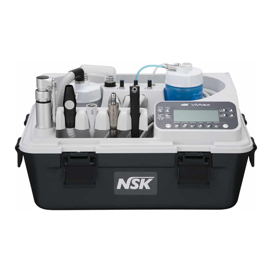
Part Names Control Unit Water Plug (OUT) [Blue Tube] Water Plug (IN) [Clear Tube] Syringe Water Adjuster Motor Water Adjuster Vacuum Connector Scaler Water Adjuster Syringe Connector Scaler Connector Motor Connector Control Panel Buckle (4 Places) Holder Bar Holder Arm Lock Holder Holder Bar Lock Holder Arm... - Page 10 Part Names Power Switch Power Inlet Fuse Holder Foot Control Connector (For Vacuum) Foot Control Connector (For Motor/Scaler) Outlet (For internal cooling) *The outlet on the other side is for Vacuum Handle Latch (2 Places) Belt Hook (4 Places, For Shoulder Belt) Shoulder Belt...
-
Page 11: Control Panel
Part Names Control Panel Keys of the Control Panel Liquid Crystal Display of the Control Panel *The illustration above shows all the marks. NOTICE • A protective sheet is applied on the liquid crystal display to prevent flaws during shipping. Remove the sheet before using the product. When removing the sheet, minor change on the liquid crystal display may be noticed. - Page 12 Part Names Name Display Function Selecting the suitable mode and the gear ratio (1:1, 1:5) for general MOTOR Key cutting and tooth surface cleaning. ENDO Key Selecting the suitable mode for root canal treatment. LIGHT PROBE Key Selecting Light Probe Mode Selecting Ultrasonic Scaler SCALER Key At the same time, selecting the Treatment Mode (P, E, G)
-
Page 13: Preparation For Use
Preparation for Use Preparation of Control Unit Action Fig. Open the Latch at the left and right of the Top Case Cover and take the Top Cover Case off. Take out the AC Power Cord and Foot Control (FC-76S, FC-70S). Unlock the 4 buckles on the front and back of the Control Unit and remove the Top Case from the Control Unit. -
Page 14: Connecting The Syringe
Preparation for use CAUTION • Be careful not to get fingers caught when turning the holder • The holder cannot be turned to the direction shown in the while pressing the Holder Arm Lock. It may cause injuries. illustration. Turning by force could cause breakage and deformation. -
Page 15: Connecting The Motor
Preparation for use Connecting the Motor * VIVA ace Motor Kit (Optional) Action Fig. Aligning the hole on the back of the Motor and the pin on the Motor Cord Connector, Hole insert the pin straight into the hole and tighten the Motor Cord Nut firmly. -
Page 16: Installing The Vacuum Bottle
Preparation for use Installing the Vacuum Bottle Action Fig. Remove the Vacuum Cap A/B. Remove the Vacuum Bottle Lid and confirm that there is no Vacuum Vacuum Loosen Cap A Cap B foreign substance inside. Aligning the filter guide pin and the notch of the filter, insert the filter until it meets the end. -
Page 17: Installing The Vacuum Hose
Preparation for use Installing the Vacuum Hose Action Fig. Remove the Hose Cap and insert the Vacuum Hose to the Vacuum Bottle Lid until it meets the end. Vacuum Hose Insert the Vacuum Valve to the Vacuum Hose until it meets the end. -
Page 18: Connecting The Foot Control
Preparation for use CAUTION • Be sure to use drinking water only. • Use of Saline, liquid medicine, high acid water may cause a failure. • Incomplete installation may cause leakage of air and water. • Do not place the Water Bottle anywhere other than the designated place as this may cause water leakage. •... -
Page 19: Check Before Treatment
Authorized NSK Dealer. CAUTION • Wait before turning on and using the VIVA ace, until it has adapted to the ambient temperature (E.g. after a cold night in the car). Note the admissible operation conditions (Reference: 12-1 Specifications). -
Page 20: Operation Procedure
Operation Procedure Motor Select the gear ratio Set the speed Gear Ratio Speed (min Interval (min 5,000 - 200,000 5,000 1,000 - 40,000 1,000 *When the motor is running, it displays the actual speed. When the motor is not running, it displays the maximum set speed. *The speed can be continuously changed during operation. -
Page 21: Motor
Operation Procedure Motor <Endodontic treatment> Change to Speed Setting ENDO Mode Speed (min Interval (min 100 - 1,000 1,000 - 5,000 *When the motor is running, it displays the actual speed. When the motor is not running, it displays the maximum set speed. *The speed can be continuously changed during operation. - Page 22 Operation Procedure <Auto Reverse Function> The following rotation modes can be selected when the load reaches the torque setting value during the ENDO Mode. AUTO REVERSE FORWARD Stops when the load reaches the torque setting value, starts reverse rotation, and when the load is removed, it automatically goes back to forward rotation.
-
Page 23: Ultrasonic Scaler
Operation Procedure Ultrasonic Scaler Select the treatment mode Power Setting P : PERIO Mode 1 to 10 E : ENDO Mode *Set it below the maximum power of the tip. *The power can be changed during operation. G : GENERAL Mode (The value continuously increases/decreases by holding down the button.) For Vacuum function,... -
Page 24: Vacuum
Operation Procedure Vacuum Select the suction force Weak/Medium/Strong Activate/Stop the Vacuum Two ways to activate/stop the Vacuum are shown below. When using FC-70S Foot Control Step on the pedal Activate Release the pedal Stop Vacuum Vacuum ON/OFF Valve Lever During treatment Manual Operation ON/OFF Close Suctioning stops by closing the... -
Page 25: Light Probe
Operation Procedure NOTICE • Do not suck exceeding the maximum line (300 ml) of the Vacuum Bottle. Sucked liquid (saliva, blood, etc.) may get into the Control Unit and cause abnormal smell or malfunction. When the device is operating normally, the Float Spindle controls the suctioning to prevent over suctioning. -
Page 26: When The Water Bottle Is Empty Or The Vacuum Bottle Is Filled With Liquid During Use
Operation Procedure WARNING • Pay close attention when blowing air from the syringe nozzle toward the patient's gingiva because procedural accidents such as subcutaneous emphysema could be caused. If any abnormality is detected, stop using the product and take appropriate procedures. NOTICE •... -
Page 27: Sound Volume
Operation Procedure Sound Volume Sound volume of Key Operation and notification tone can be set. Press the LIGHT PROBE Key Sound Volume Setting Volume : High Volume : Low Volume : Partly OFF* *Sound which rings around the torque setting value and during the auto reverse operation during the ENDO mode are OFF <Types of sound>... -
Page 28: Last Memory Function
Operation Procedure Last Memory Function About setting of the each mode after the Main Power was turned off. In case of each mode (MOTOR, ENDO, SCALER, LIGHT PROBE): -The setting will be back to an initial state, when turning on the Main power. In case of light quantity, sound volume, and the Vacuum suction force: -The last settings are saved. -
Page 29: Protection Circuit
Operation Procedure 6-11 Protection Circuit The protection circuit will be activated and stop the device to prevent from danger and breakage when the device is operated with the load exceeding its maximum value. The error code will be displayed in the display panel. (Reference:11-1 Error Code) <Motor>... -
Page 30: Post-Use Maintenance
Post-use Maintenance After each patient maintain the product as follows. Preparation Action Fig. Wear eye protection, a mask, and gloves to prevent infection. Turn off the Power Switch of the Control Unit. First, remove the Water Plug (IN) [Clear Tube] while pulling the Slide Ring. -
Page 31: Maintenance For Between Each Patient
Post-use Maintenance Maintenance for between each patient 7-2-1 Cleaning (Vacuum Hose) Action Fig. Remove the Vacuum Bottle from the Control Unit with the Vacuum Hose attached. Close Remove Vacuum Remove Valve Lever Remove the Vacuum Hose and the Vacuum Bottle Lid, then dispose of the sucked liquid (saliva, blood, etc.) in the bottle. - Page 32 Operation Procedure Cleaning and Disinfection of the outside of the 7-2-2 Motor and the Motor Cord, and Replacing the Motor Action Fig. <Cleaning> Remove the all debris on the surface of the Handipiece, Motor and the Motor Cord with a wipes (Minuten Wipes: ALPRO).
- Page 33 Post-use Maintenance Cleaning and Disinfection of outside of the Scaler Handpiece and 7-2-3 the Scaler Cord, and Replacing the Scaler Handpiece (continued) Action Fig. <Disinfection> Wipe the surface of the Scaler Handpiece and the Scaler Cord with the disinfectant wipes (Minuten Wipes: ALPRO). Disconnect the Scaler Handpiece from the Scaler Cord, then attach a sterilized Scaler Handpiece and place it on the Holder.
-
Page 34: Maintenance After Close
Post-use Maintenance Maintenance After Close 7-3-1 Cleaning (Vacuum Hose, Vacuum Bottle) Action Fig. Turn off the Power Switch of the Control Unit. Close Remove Vacuum Remove Close the Vacuum Valve Lever. Valve Lever Remove the Vacuum Junction Hose at the Vacuum Bottle side only. - Page 35 Post-use Maintenance 7-3-1 Cleaning (Vacuum Hose, Vacuum Bottle) (Continued) Action Fig. Wipe the water on the outside of each part with a wrung out cloth. Wipe with the disinfectant wipes (Minuten Wipes: ALPRO). Minuten Wipes Wrung out cloth (ALPRO) Attach the Gasket to the Vacuum Bottle Lid. Gasket (thickness 1 mm) Gasket (Black)
- Page 36 Post-use Maintenance Action Fig. Close the Vacuum Valve Lever. Close Remove Vacuum Stop VACUUM and then turn off the Power Switch of the Valve Lever Control Unit. Remove the Vacuum Junction Hose from the Vacuum Bottle side only. Remove the Vacuum Bottle from the Control Unit with the Vacuum Hose attached.
- Page 37 Post-use Maintenance 7-3-3 Cleaning (Water Bottle) Action Fig. Remove the Water Bottle Lid. Clean the inside and the outside of the Water Bottle and the Lid under running water. Loosen * For the remaining dirt, use a soft bristled brush to remove the dirt.
- Page 38 Post-use Maintenance 7-3-5 Cleaning of the outside of the Scaler Handpiece Action Fig. <Cleaning> Remove the all debris on the surface of the Scaler Handpiece and the Scaler Cord with the wipes (Minuten Wipes: ALPRO). Remove the Tip from the Scaler Handpiece. Remove the Scaler Handpiece from the Scaler Cord.
- Page 39 Post-use Maintenance Manual Cleaning and Disinfection (Including the Water line) 7-3-6-1 (In case of connecting to the adapter) WL-Adapter 01 (ALPRO) is to be prepared by customers. Cleaning and Disinfection should be done in the cleaning tank. Action Fig. Attach the WL-Adapter 01 (ALPRO) to the WL-clean (ALPRO) and contact the 1, 5 Water Water Connector on the Scaler Handpiece to the end of the WL-Adapter 01...
- Page 40 Post-use Maintenance Action Fig. Discharge the disinfectant solution from the Water Line on the Scaler Handpiece. · When using the WL-dry (ALPRO): For details, confirm the operation manuals issued by manufacturer. · When using the WL-dry (ALPRO): Spray time: 3 seconds Number of spray: 1 time ·...
- Page 41 Post-use Maintenance 7-3-6-2 Automated Cleaning and Disinfection (Including the Water line) CAUTION • Scaler Cord cannot be cleaned with washer-disinfector. • Use a cleaning and disinfection device (washer-disinfector) complying with DIN EN ISO 15883 (e.g. Miele washer-disinfector G7781/G7881; Melag Melatherm), that operates with a maximum pH value of 10.5 (e.g. neodisher, Dr. Weigert) and is equipped with the appropriate adapters.
- Page 42 CAUTION • Do not use a sharp tool to clean the Glass Rod. It could damage the glass and reduce the light transmission. When this happens, please contact your Authorized NSK Dealer. 7-3-8 Cleaning and Disinfection of the Scaler Cord Action Fig.
- Page 43 Post-use Maintenance 7-3-9 Cleaning and Disinfection (Syringe, Syringe Nozzle) < Syringe Nozzle > Action Fig. Remove the Syringe Nozzle from the Syringe. Clean the outside and the inside of the Syringe Nozzle under running water. * Make sure there is no dirt remaining after cleaning. When there is remaining dirt, repeat cleaning until dirt is completely cleaned away.
-
Page 44: Sterilization
Post-use Maintenance Sterilization Autoclave the Suction Tube and the Syringe Nozzle. Sterilization of the Handpieces, the Motor, the Scaler Handpieces, the Tips and the Tip Wrench should be done in accordance with each operation manual. After each patient, sterilize the parts as follows. 7-4-1 Preparation before sterilization Insert the autoclavable products and parts individually into a sterilization case or sterilization pouch that conform to ISO 11607-1, and seal the... -
Page 45: Maintenance Before Use
Post-use Maintenance 7-4-2 Sterilization (Continued) CAUTION • Only the Suction Tube and the Syringe Nozzle can be sterilized. No other parts can be sterilized. Option parts (Motor and Ultrasonic Scaler) should be maintained in accordance with the attached operation manuals. •... -
Page 46: Maintenance Of The Water Line
Post-use Maintenance Maintenance of the Water Line Disinfection with Alpro Bilpron (undiluted) is recommended as maintenance once or twice a week. 7-6-1 Preparation of the Water Line before Disinfection Action Fig. Put 200 mL of disinfectant solution in the Water Bottle. Tightly close the Water Bottle lid and place the Water Bottle in the Control Unit * For details, confirm the operation manuals issued by... - Page 47 Post-use Maintenance CAUTION • Disinfectant solution remains in the Water Line by letting the solution out from the tip of the Motor, Scaler Handpiece, and the Syringe. • It takes 12 hours to complete the disinfection after disinfectant solution remain on the Water Line of the Motor, the Scaler Handpiece, the Tip, Tip Wrench and the Syringe.
- Page 48 Post-use Maintenance Action Fig. Turn on the Power Switch of the Control Unit. Maximize each Water Adjuster. < Motor / Scaler Handpiece > Select the mode and turn on the SPRAY Key. < Syringe > Make sure that the Syringe Nozzle is attached. Scaler Hold the Motor and the Motor Cord / the Scaler Handpiece and the Scaler Motor...
-
Page 49: Storage Procedure
Storage Procedure Action Fig. Turn off the Power and pull the AC Power Cord and the Foot Control Cord. Vacuum Valve Lever Close the Vacuum Valve Lever. Remove the Handpiece, the Syringe Nozzle, and the Suction Tube and place them in the Holder. Place the Water Bottle and the Vacuum Bottle in the designated position of the Control Unit. - Page 50 NOTICE • Follow <Point 1> and <Point 2> to store the cords and hoses smoothly. • Storage of cords and hoses is introduced in a video. Check the URL or the QR code below. http://www.nsk-dental.com/support/videos/ Action Fig. Release the Holder Arm Lock, support the Holder to prevent the cords and hoses from dropping, and then turn the Holder slowly until it reaches its lowest to lock.
-
Page 51: Transportation
Transportation Action Fig. Confirm that the buckles (4 places) in the front and the back of the Control Unit are firmly locked. Set the Shoulder Belt securely to the Belt Hook. Check Carry the device hung the Shoulder Belt on the shoulder. CAUTION •... -
Page 52: Replacing The Filter, Gasket, O-Ring (Vacuum Bottle)
Maintenance 10-2 Replacing the filter, gasket, O-ring (Vacuum Bottle) Action Fig. Take off the Vacuum Bottle Lid. Gasket Gasket (Black) (Thickness 1 mm) Remove the filter and the guide from the lid, and then remove the gasket (black) and the gasket using tweezers. Loosen Remove the O-ring on the Vacuum Connector using O-ring... -
Page 53: Replacing The O-Ring (Syringe)
Maintenance 10-6 Replacing the O-ring (Syringe) Action Fig. Remove the nut using the attached spanner. Flat Washer O-ring Tighten Remove the O-rings using tweezers. O-ring catcher Loosen Place new O-rings. O-ring After attaching the O-ring Catcher to the nut, place the nut on the Syringe and tighten lightly with fingers. -
Page 54: Drainage Of Air Filter
Maintenance 10-8 Drainage of Air Filter Action Fig. Using a cross-head screw driver, remove the filter cover at the bottom of the control unit. Press the end part of the air filter for drainage. Prepare for the drainage because the drained water contains air and may Loosen Tighten spray out onto surrounding objects. -
Page 55: Periodical Maintenance Checks
10-10 Periodical Maintenance Checks Every 3 months perform periodical maintenance checks, referring to the check sheet below. If any abnormalities are found, contact your Authorized NSK Dealer. Points to check Details Check if there is no discoloration, deformation, or breakage. -
Page 56: Troubleshooting
Press Motor/Scaler ON/OFF Key or step on the foot control (FC-76S) again or turn on the device again to see if the error is canceled. If the error code is displayed again, refer to the following table and take appropriate actions. When the error is not eliminated, a failure of this device is suspected. Contact your Authorized NSK Dealer. Error Code... - Page 57 Object Cause of the Error Remedy Abnormal pressure Err 18 Contact your Authorized NSK Dealer. (Abnormality in the AD value of the pressure sensor) Use within the temperature range of the use Err 19 Abnormal temperature in the Control Unit environment.
-
Page 58: Problems And Solutions
When a problem is detected, check the following again before requesting a repair. If none of these is applicable or if the trouble is not remedied even after an action has been taken, a failure of this product is suspected. Contact your Authorized NSK Dealer. Problem... -
Page 59: Specifications
Specifications 12-1 Specifications Model VIVA ace Dimension W438 x D298 x H284 mm (Belt Hook not included) Weight 8.5 kg (Basic Set) <Control unit> Model NE322 Power-supply voltage AC100 – 240 V Power frequency 50/60 Hz Power input 130 VA Vacuum suction force 3.3 –... -
Page 60: Symbol
Specifications 12-3 Symbol This product is Autoclavable up to Max. 135ºC. Conforms to CE European Directive of “Medical device directive 93/42/EEC.” This product can be cleaned using washer-disinfector. Manufacturer. Authorized representative in the European community. Follow the waste of electric and electronic equipment (WEEE) Directive (2012/19/EU) for product and accessory disposal. Consult operation instructions. -
Page 61: After-Sales Service
Warranty is voided should the product be not used correctly or for the intended purpose or has been tampered with by unqualified personnel or has had non NSK parts installed. Replacement parts are available for seven years beyond discontinuation of the model. -
Page 62: Option Parts List
After-sales Service 13-3 Option Parts List Model Order Code Model Order Code VIVA ace Motor Kit E1040002 VIVA ace Scaler Kit E351006 Model Order Code isoE-LUX (Light Probe) Z1265 13-4 Disposing product In order to avoid the health risks of operators handling the disposal of medical equipment, as well as the risks of environmental contamination caused thereof, a surgeon or a dentist is required to confirm the equipment is sterile. -
Page 63: (Electromagnetic Compatibility Information)
EMC Information (Electromagnetic Compatibility Information) Guidance and manufacturer's declaration - Electromagnetic Emissions The product is intended for use in the electromagnetic environment specified below. The customer or the user of the product should assure that it is used in such an environment. Emissions test Compliance Electromagnetic environment - guidance... -
Page 64: Emc Information
EMC Information Guidance and manufacturer's declaration - Electromagnetic Immunity The product is intended for use in the electromagnetic environment specified below. The customer or the user of the product should assure that it is used in such an environment. Immunity test EN/IEC60601 test level Compliance level Electromagnetic environment - guidance... - Page 65 EMC Information Cables and accessories Maximu Complies with Class B/Group 1 AC Power Cord 2m (Unshielded) RF emissions, CISPR11 Harmonic emissions EN/IEC61000-3-2, Class A Voltage flucturations/flicker emission EN/IEC61000-3-3 Foot Control (FC-76S) 1.5m (Unshielded) Electrostatic discharge (ESD) IEC61000-4-2 Electrical fast transient/burst IEC61000-4-4 Surge: IEC61000-4-5...
- Page 66 2018.08.10 002...
Need help?
Do you have a question about the Viva Ace and is the answer not in the manual?
Questions and answers