Table of Contents
Advertisement
Quick Links
Advertisement
Table of Contents

Related Manuals for Electro-Voice EVID-P6.2B


Summary of Contents for Electro-Voice EVID-P6.2B
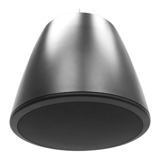
- Page 1 EVID Pendant Speaker EVID‑P6.2B | EVID‑P6.2W Installation manual...
-
Page 3: Table Of Contents
Installing the weather cover – optional accessory Wiring Step 1 – Attach wiring to the terminal connector Step 2 – Adjust tap selector Step 3 – Attach the grille Troubleshooting Technical data Electro-Voice Installation manual 2018.09 | 03 | F.01U.358.439... -
Page 4: Safety
Suspending any object is potentially dangerous and should only be attempted by individuals who have a thorough knowledge of the techniques and regulations of suspending objects overhead. Electro-Voice strongly recommends that loudspeakers be suspended taking into account all current national, federal, state, and local laws and regulations. It is the responsibility of the installer to ensure all loudspeakers are safely installed in accordance with all such requirements. - Page 5 For information on getting permission for reprints and excerpts, contact Electro-Voice. All content including specifications, data, and illustrations in this manual are subject to change without prior notice.
-
Page 6: Introduction
Product information Figure 2.1: Product identification Item Component Pendant speaker Input terminal Secondary auxiliary support Main suspension tab Tap selector Grille (installed) Grille removal tool Pendant suspension cable Coupler Support hanger 2018.09 | 03 | F.01U.358.439 Installation manual Electro-Voice... -
Page 7: Packing List
Do not hang the pendant suspension cable at an angle in excess of 60° from vertical. 5.0 kg 7.1 kg 8.7 kg 9.7 kg 10 kg 9.7 kg 8.7 kg 7.1 kg 5.0 kg 15° 15° 30° 30° 45° 45° 60° 60° LOAD Figure 2.3: Working load limit Electro-Voice Installation manual 2018.09 | 03 | F.01U.358.439... -
Page 8: Installation
To install the pendant speaker, do the following: Thread the cable into the coupler. Adjust the pendant suspension cable length. Place the pendant suspension cable over the ceiling support. Thread the cable into the opposite side of the coupler. 2018.09 | 03 | F.01U.358.439 Installation manual Electro-Voice... - Page 9 Secure the secondary auxiliary support cable (not included) to a different ceiling support point of the building structure. See also – Safety, page 4 – Wiring, page 13 Electro-Voice Installation manual 2018.09 | 03 | F.01U.358.439...
-
Page 10: Installing With The Threaded Rod Adapter - Optional Accessory
Align mounting slot, if needed. Screw jam-nut down until it contacts the surface of the threaded rod adapter. Fully tighten against each other. Insert pendant mounting plate into threaded rod mounting slot. 2018.09 | 03 | F.01U.358.439 Installation manual Electro-Voice... -
Page 11: Installing The Weather Cover - Optional Accessory
Installing the weather cover – optional accessory To wire the speaker using Euroblock connector and weather cover, do the following: Mount the speaker, as shown in the installation section. Loosen the gland nut. Electro-Voice Installation manual 2018.09 | 03 | F.01U.358.439... - Page 12 Loosely tighten the three screws to keep the weather cover in place. Tighten all three screws to secure the weather cover. Ensure the weather cover is secure. Adjust the wire length. Tighten the gland nut. 2018.09 | 03 | F.01U.358.439 Installation manual Electro-Voice...
-
Page 13: Wiring
Connect the wire pair of the subsequent speaker to pins 1 and 4. When one input connector is removed, subsequent speakers will also be disconnected. From amplifier or To next speaker previous speaker Figure 4.3: Daisy-Chain wiring Electro-Voice Installation manual 2018.09 | 03 | F.01U.358.439... -
Page 14: Step 2 - Adjust Tap Selector
If you need to remove the grille, the easiest way is to use the provided grille removal tool, then apply slow even pressure to pull down on the grille until it detaches from the speaker. The grille is attached magnetically to the speaker. 2018.09 | 03 | F.01U.358.439 Installation manual Electro-Voice... - Page 15 EVID Pendant Speaker Wiring | en Figure 4.5: Attach the grille See also – Installation, page 8 Electro-Voice Installation manual 2018.09 | 03 | F.01U.358.439...
-
Page 16: Troubleshooting
Poor System Check and correct the system grounding, as required. Grounding or Ground Loop If these suggestions do not solve your problem, contact your nearest Electro-Voice dealer or Electro-Voice distributor. See also – Installation, page 8 –... -
Page 17: Technical Data
Included accessories: Grille removal tool Average 1 kHz to 10 kHz Pendant Suspension Cable Material: Steel wire rope Working load limit: 10 kg (22 lb) Length: 4.57 m (15 ft.) Approvals: UL2442 Electro-Voice Installation manual 2018.09 | 03 | F.01U.358.439... - Page 18 [12.20 in.] Frequency response and impedance: 31.6 3.16 Frequency Response, Full Space, 8 Ohm Tap Impedance, 8 Ohm Tap 1000 10000 20000 Frequency (Hz) Beamwidth: Horizontal Vertical 10000 20000 1000 Frequency (Hz) 2018.09 | 03 | F.01U.358.439 Installation manual Electro-Voice...
- Page 19 EVID Pendant Speaker Technical data | en Directivity: 1000 1000 10000 20000 Frequency (Hz) Electro-Voice Installation manual 2018.09 | 03 | F.01U.358.439...
- Page 20 Bosch Sicherheitssysteme GmbH Bosch Security Systems, Inc Robert-Bosch-Ring 5 12000 Portland Avenue South 85630 Grasbrunn Burnsville MN 55337 Germany www.boschsecurity.com www.electrovoice.com © Bosch Sicherheitssysteme GmbH, 2018...
Need help?
Do you have a question about the EVID-P6.2B and is the answer not in the manual?
Questions and answers