
Related Manuals for Oerlikon Leybold Vacuum Turbovac SL 300


Summary of Contents for Oerlikon Leybold Vacuum Turbovac SL 300
- Page 1 TURBOVAC SL 300 Wide-Range Turbomolecular Pump with Integrated or External Frequency Converter Operating Instructions 130000761_002_A0 Part Nos. 800170V3005 800170V3006...
-
Page 2: Table Of Contents
3.3.1 RS 232 C interface (SERVICE X5) 3.3.2 RS 485 interface 3.3.3 Profibus DP 3.3.4 Ethernet/IP interface 3.3.5 Parameter list 3.3.6 Warning codes for parameter 227 Switching on Shutting down Venting Bakeout Removing the pump from the system 130000761_002_A0 - 08/2008 - © Oerlikon Leybold Vacuum... -
Page 3: Important Safety Information
Indicates procedures that must be strictly observed to prevent damage to, or destruction of the product. The Oerlikon Leybold Vacuum TURBOVAC SL 300 has been designed for safe and efficient operation when used properly and in accordance with these Operating Instructions. It is the responsibility of the user to carefully read and strictly observe all safety precautions described in this section and throughout the Operating Instructions. - Page 4 European manufacturers of vacuum pumps strictly recommend to follow the installation instructions as given in this manual. After a mains power failure the pump can run up automatically once more. 130000761_002_A0 - 08/2008 - © Oerlikon Leybold Vacuum...
- Page 5 Contaminated parts can be detrimental to health and environment. Before beginning to work, find out whether any parts are contaminated. Adhere to the relevant regulations and take the necessary precautions when handling contaminated parts. 130000761_002_A0 - 08/2008 - © Oerlikon Leybold Vacuum...
- Page 6 Ensure correct polarity when connecting the TURBO.DRIVE. A wrong polarity may cause an internal fuse to blow. The fuse can only be changed by the Oerlikon Oerlikon Leybold Vacuum Service. The interface connectors have UNC 4-40 threads. Do not use connectors with M3 treads.
-
Page 7: Description
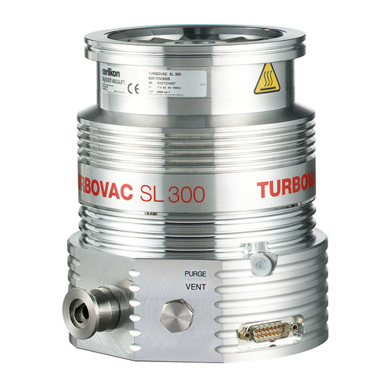
Fig. 1.1 Examples of SL 300 Description The TURBOVAC SL 300 is a wide range turbomolecular pump designed to evacuate vacuum chambers down to pressure levels in the high vacuum range. It is suitable for pumping air and clean gases. The TURBO.DRIVE 400 frequency converter and a forevacuum pump are required for its operation. -
Page 8: Design
———————————— PE = Polyethylene FPM = Fluororubber, resistant to temperatures up to 150°C (302 °F) 130000761_002_A0 - 08/2008 - © Oerlikon Leybold Vacuum... -
Page 9: Technical Data
+15 - + 30 °C storage -15 - + 70 °C Max. rel. air humidity 95% (non-condensing) Purge gas flow 12 sccm / 0,2 mbar l·s Purge gas Nitrogen, Argon or similar 130000761_002_A0 - 08/2008 - © Oerlikon Leybold Vacuum... - Page 10 Temp. of the cooling surface 5 - 55 °C For Part Nos. 800073V0004 /07 5 - 50 °C Power consumption ≤ 20 W Type of protection IP 20 Weight, approx. 0.5 kg 130000761_002_A0 - 08/2008 - © Oerlikon Leybold Vacuum...
- Page 11 Adapter centering ring DN 10/16 KF with sinter filter Gas connection G1/4-in. Recommended for this: Adapter with filter including O-ring and gasket 800110V0012 Dimensions 60 x 65 x 45 mm 61 x 65 x 45 mm 130000761_002_A0 - 08/2008 - © Oerlikon Leybold Vacuum...
- Page 12 Ø 140 Ø130 Ø 154 100 ISO-K 181 100 CF Air cooler connection Fan connection Ø 140 Ø 130 Ø154 Fig. 1.3 Dimensional drawings for SL 300 pumps (combination examples); dimensions in mm 130000761_002_A0 - 08/2008 - © Oerlikon Leybold Vacuum...
- Page 13 100 CF DN 16 KF DN 16 KF Ø 154 Purge gas connection Ø 154 Ø 140 Ø 130 Fig. 1.4 Dimensional drawings for SL 300 pumps (combination examples); dimensions in mm 130000761_002_A0 - 08/2008 - © Oerlikon Leybold Vacuum...
-
Page 14: Ordering Data
864 49 3.0 m long 864 40 5.0 m long 864 50 Mounting kit TD 400 for TURBOVAC SL 300 Including 0.2 m long connection cable pump - frequency converter For installing the frequency converter ... beside the pump 800110V0006 ... - Page 15 200 12 732 200 12 733 10 m 200 12 734 20 m 200 12 735 Mains cable for power supply, 2 m long with EURO plug 800102V0001 with US plug 5-15P 800102V1001 130000761_002_A0 - 08/2008 - © Oerlikon Leybold Vacuum...
- Page 16 Plug for connector REMOTE with integrated ON/OFF switch for the pump (Sub-D plug, 9 way) 152 48 Heat sink for frequency converter 800110V0001 Top hat rail adaptor (mounting aid for TURBO.DRIVE 400 and TURBO.POWER 300) 800110V0003 130000761_002_A0 - 08/2008 - © Oerlikon Leybold Vacuum...
- Page 17 DN 100 ISO-K 268 42 Clamps (Set of 4 pieces) 267 01 Centering ring with O-ring for DN 16 KF Al/CR 183 26 Al/FPM 182 06 Clamping ring (Al) DN 16 KF 183 41 130000761_002_A0 - 08/2008 - © Oerlikon Leybold Vacuum...
-
Page 18: Installation
Installation Installation Conforming utilization The TURBOVAC SL 300 is a wide range turbomolecular pump designed to evacuate vacuum chambers down to pressure levels in the high vacuum range. It is suitable for pumping air and clean gases. The TURBO.DRIVE 400 frequency converter and a forevacuum pump are required for its operation. -
Page 19: Fitting Accessories
The cooling water may be connected radially or axially to the connecting piece of the cooling coil; see Fig. 2.1. Blank off the unused G 1/8” threads using the screw-in stoppers and gaskets supplied. 130000761_002_A0 - 08/2008 - © Oerlikon Leybold Vacuum... - Page 20 When fitting as shown in the figures, the 0.2 m long cable will do for the frequency converter. When the power supply connector shall point in the other direction, then the 0.4 m long cable will be needed. 130000761_002_A0 - 08/2008 - © Oerlikon Leybold Vacuum...
- Page 21 As the purge gas and venting valve use either valves with a M8 screw-in thread or screw in the M8 – DN16KF adapter and connect the valve to it. See also Section 2.7. 130000761_002_A0 - 08/2008 - © Oerlikon Leybold Vacuum...
-
Page 22: Attach The Pump To The Vacuum Chamber
800 Nm will have to be absorbed by the system. To accomplish this, the fol- lowing is required: ISO-K flange: 6 steel clamps, strength at least 8.8, torque 30 Nm CF flange: stainless steel screws, strength at least A2-70, torque 20 Nm 130000761_002_A0 - 08/2008 - © Oerlikon Leybold Vacuum... - Page 23 Applications Dept. in order to prevent that the pumps will be excited by vibra- tions by each other. Besides the forevacuum connection it is possible to connect a vibration sen- sor: thread M3, 9.3 mm deep. 130000761_002_A0 - 08/2008 - © Oerlikon Leybold Vacuum...
- Page 24 A collar flange with circlip and the appropriate gasket may be used to connect the pump. A collar flange is required when using ultra-vacuum sealing gaskets. The order numbers for the flange components are given in the Oerlikon Leybold Vacuum Catalog. 130000761_002_A0 - 08/2008 - © Oerlikon Leybold Vacuum...
-
Page 25: Forevacuum Connection
In this case the pressure in the forevacuum line must be over 10 mbar. Provide a roughing line to achieve the shortest cycle times. Ensure that the pump is sufficiently isolated against vibrations generated by the forevacuum pump. 130000761_002_A0 - 08/2008 - © Oerlikon Leybold Vacuum... -
Page 26: Connect The Cooling
Nos. see Section 1.5. Air cooling When installing air cooled pumps within a system ensure that sufficient quan- tities of fresh air are freely available. The air cooling facility is powered via the pump. 130000761_002_A0 - 08/2008 - © Oerlikon Leybold Vacuum... - Page 27 For pumps with a CF flange and Argon in the case of special applica- tions please ask us for informa- tion. 10,5 12,0 Forevacuum pressure in mbar VV-Druck in mbar Fig. 2.8 Cooling requirements of the SL 300 130000761_002_A0 - 08/2008 - © Oerlikon Leybold Vacuum...
- Page 28 Example: Max. ambient temperature 25 °C °C Min. coolant inlet temperature 17 °C Minimum coolant inlet temperature ⇒ Max. relative humidity Fig. 2.10 Dewpoint diagram 130000761_002_A0 - 08/2008 - © Oerlikon Leybold Vacuum...
- Page 29 When switching the cooling water supply on and off by means of an electric- ally actuated valve, connect the valve so that it will be switched on and off together with the pump. 130000761_002_A0 - 08/2008 - © Oerlikon Leybold Vacuum...
-
Page 30: Connecting The Purge Gas / Venting Valve
Consider the additional purge gas flow when selecting a suitable backing pump. We recommend a purge gas flow of 0.2 mbar·l/s (12 sccm) with Nitrogen. The pressure in the pump must not exceed 1200 mbar (0.2 bar over- pressure). 130000761_002_A0 - 08/2008 - © Oerlikon Leybold Vacuum... - Page 31 High-vacuum valve Valve in the roughing pump line 10 Frequency converter — — — — Roughing line; recommend to achieve the shortest possible cycle times Fig. 2.13 Schematic of a turbomolecular pump system 130000761_002_A0 - 08/2008 - © Oerlikon Leybold Vacuum...
-
Page 32: Electrical Connection
(15 way Sub-D plug X3). Connect the Sub-D-plugs with the hexagon threaded bolts UNC 4/40x6 at the pump connector. Make sure that the frequency converter is adequately cooled; for this see Section 2.8.3 and also Fig. 2.17. 130000761_002_A0 - 08/2008 - © Oerlikon Leybold Vacuum... - Page 33 Frequency converter TURBO.DRIVE 400 (Cooler optional) Mains Power supply DC cable, with shielding, max. 20 m 24 V DC cable, max. 5 m Fig. 2.14 Examples for connection 130000761_002_A0 - 08/2008 - © Oerlikon Leybold Vacuum...
-
Page 34: Connecting The Power Supply
Connect the frequency converter to the 24 V DC power supply or to the TURBO.CONTROL 300 or to the TURBO.POWER 300 via the 24 V DC cable. Caution Ensure correct polarity. Pin 1 + 24 VDC Pin 2 Pin 3 130000761_002_A0 - 08/2008 - © Oerlikon Leybold Vacuum... -
Page 35: Mounting The Frequency Converter
Fig. 2.17 Cooling requirements for the TURBO.DRIVE 400 when fitted separately The frequency converter is equipped with an internal 8 AT (slow blow) fuse. It can only be replaced by Oerlikon Leybold Vacuum staff. Connect the power supply to the mains. - Page 36 No error, no warning flashes: Warning is present, pump can be operated possibly with some restrictions Fault is present, pump stopped or can not be operated Fig. 2.18 TURBO.DRIVE 400, front and rear side 130000761_002_A0 - 08/2008 - © Oerlikon Leybold Vacuum...
- Page 37 Fig. 2.19 Pin assignment of the REMOTE (X1) connector 0 V = STOP 24 V 24 V = START TURBO.DRIVE 400 GA 06.215 EYBOLD AG 00.00.S.001 24 V 21.11.94 9er Buchsenbelegung WERK KÖLN Fa. ESCH TURBO.DRIVE 400 130000761_002_A0 - 08/2008 - © Oerlikon Leybold Vacuum...
-
Page 38: Relay Status
Error has just occurred Start passive active Error is present; pump is at standstill Start passive active flashes Error is present; pump is decelerating Start passive active flashes Error has just occurred 130000761_002_A0 - 08/2008 - © Oerlikon Leybold Vacuum... -
Page 39: Operation
Operation Operation Media compatibility / purge gas The TURBOVAC SL 300 is suitable for pumping air and clean gases. These pumps are not suitable for pumping liquids or gases containing dust or particulates pumping corrosive or reactive gases pumping gas mixtures with an oxygen share of > 21 % If reactive gases in low concentrations must be pumped operate the pump with purge gas. -
Page 40: Interfaces
P29 Set motor current thresh.: P27 Lowering the normal operation Normal operating mode is attained Reduce frequency threshold threshold faster, processes can be started faster through P25 130000761_002_A0 - 08/2008 - © Oerlikon Leybold Vacuum... -
Page 41: Rs 232 C Interface (Service X5)
Note: If on the controlling side an RS 232 interface in accordance with the PC standard with a 9-pin Sub-D male connector is present, then a straight through cable as shown in Fig. 3.2 may be used. Refer also to Operating Instructions GA 05.281 130000761_002_A0 - 08/2008 - © Oerlikon Leybold Vacuum... -
Page 42: Rs 485 Interface
(yellow power LED off) and then on again so as to enable the new address setting. Bus addresses over 15 can only be set via Parameter 37. Refer also to Operating Instructions GA 05.281 130000761_002_A0 - 08/2008 - © Oerlikon Leybold Vacuum... -
Page 43: Profibus Dp
Refer also to Operating Instructions GA 05.281 3.3.4 Ethernet/IP interface See additional Operating Instructions 17200908. The Operating Instruction will be delivered on a CD with Part No. 800073V0007 or can be downloaded from our website. 130000761_002_A0 - 08/2008 - © Oerlikon Leybold Vacuum... -
Page 44: Parameter List
8 = No mains power failure or no generator operation (P303 Bit 4 =1 = generator operation) Field 1 specifies the function for the error relay: 0 = Energised when an error is present 1 = Deenergised when an error is present 2 = Fieldbus controlled 130000761_002_A0 - 08/2008 - © Oerlikon Leybold Vacuum... - Page 45 Intermediate circuit 0,1 A Actual average intermediate circuit current current of the converter. Standby frequency 1200 Standby operation frequency setpoint Enable standby 0 = normal speed (P24); 1 = standby speed (P150) 130000761_002_A0 - 08/2008 - © Oerlikon Leybold Vacuum...
- Page 46 Frequency at which the venting valve shall be switched off in the event of a mains power failure. Power failure venting can be enabled through P240. Generator operation 0 = inactive 1 = active 130000761_002_A0 - 08/2008 - © Oerlikon Leybold Vacuum...
- Page 47 Serial number of the converter. converter [xxxxxxxxxxx] One ASCII char per index. (Index 0...10 usable) Act. Profibus addr. 65535 Active Profibus address Current error number 65535 Currently pending error. See Section 5 Troubleshooting. 130000761_002_A0 - 08/2008 - © Oerlikon Leybold Vacuum...
-
Page 48: Warning Codes For Parameter 227
P4 > Umax or P4 < DC power supply voltage Umin below 24V Mains voltage failure Fan voltage has failed 130000761_002_A0 - 08/2008 - © Oerlikon Leybold Vacuum... -
Page 49: Switching On
Exposure of the pump to accelerating forces must be avoided or reduced to such an extent that the rotor unit will not be excited by vibrations. In the case of critical applications you must consult our Applications Dept. first. 130000761_002_A0 - 08/2008 - © Oerlikon Leybold Vacuum... -
Page 50: Shutting Down
200 Hz. Thus the pump may still turn without a LED being on. For this reason, when switching off without venting, wait for approxi- mately 15 minutes after the LEDs have turned off until the pump has arrived at standstill. 130000761_002_A0 - 08/2008 - © Oerlikon Leybold Vacuum... -
Page 51: Venting
The slower the pump is vented, the longer the service life of the bearings will be. The pump must not be vented to pressures above atmospheric pressure. 130000761_002_A0 - 08/2008 - © Oerlikon Leybold Vacuum... -
Page 52: Bakeout
– at a sorption trap, for example – ensure that the com- ponents attached direct are not heated to more than 100 °C (212 °F). The forevacuum pump must be in operation so as to eliminate the vapors liberated at the sorption trap. 130000761_002_A0 - 08/2008 - © Oerlikon Leybold Vacuum... -
Page 53: Removing The Pump From The System
Pack the pump so that it cannot be damaged during shipping and storage. Pay particular attention to protection for the flanges and the electrical plug. Observe the instructions in Section 4.2 if you forward the pump to Oerlikon Leybold Vacuum. 130000761_002_A0 - 08/2008 - © Oerlikon Leybold Vacuum... -
Page 54: Maintenance
Moreover, we are recommending an exchange of the rotor unit after 45,000 operating hours at the latest. Such maintenance work can only be done by the Oerlikon Leybold Vacuum Service. If required contact the Oerlikon Leybold Vacuum service center nea- rest to your location. -
Page 55: Troubleshooting
In case of error code 8 by switching the mains power off. The error codes can only be read if a serial interface is present. The following table has been provided as a guide when determining the causes of errors. 130000761_002_A0 - 08/2008 - © Oerlikon Leybold Vacuum... - Page 56 Check connection between pump fied or no pump is rectly to frequency conver- and frequency converter connected Frequency converter soft- Contact Oerlikon Leybold Vacuum ware not current, Service Hardware defective Contact Oerlikon Leybold Vacuum Service 130000761_002_A0 - 08/2008 - © Oerlikon Leybold Vacuum...
- Page 57 Contact Oerlikon Leybold nominal current Vacuum Service Faulty connector Motor temperature Motor temperature sen- Sensor defective, short Contact Oerlikon Leybold sensor error sor defective circuit or broken cable Vacuum Service Overspeed error 130000761_002_A0 - 08/2008 - © Oerlikon Leybold Vacuum...
- Page 58 Running pump can not Pump has been started via the Disconnect the DC supply or connect serial be stopped via X1 serial interface, the interface con- interface and stop via bus trols the pump 130000761_002_A0 - 08/2008 - © Oerlikon Leybold Vacuum...
-
Page 59: Waste Disposal
Separate clean components according to their materials, and dispose of these accordingly. We offer this service. Further details are available on request. When sending us any equipment, observe the regulations given in Section “4.2 Oerlikon Leybold Vacuum service”. 130000761_002_A0 - 08/2008 - © Oerlikon Leybold Vacuum... -
Page 60: Ec Manufacturer's Declaration
130000761_002_A0 - 08/2008 - © Oerlikon Leybold Vacuum... -
Page 61: Ec Conformance Declaration
130000761_002_A0 - 08/2008 - © Oerlikon Leybold Vacuum... - Page 62 I / we hereby declare that the information supplied on this form is accurate and sufficient to judge any contamination level. Name of authorised person (block letters): ____________________________ Date _____________ Signatur of authorised person ___________________________ firm stamp 17200001_002_00 © Oerlikon Leybold Vacuum 130000761_002_A0 - 08/2008 - © Oerlikon Leybold Vacuum...
-
Page 63: Index
Resonance damper 23, 31 52, 58 Fuse 6, 35 Safety valve 4, 18, 25 Shock 49 Generator 44, 46-48, 50, 57 Splinter guard 8, 9, 17, 23 Split-cage DC motor 8 Starting pressure 49 130000761_002_A0 - 08/2008 - © Oerlikon Leybold Vacuum... - Page 64 Sales and Service Germany Europe Asia Oerlikon Spain P.R. China Japan Belgium Leybold Vacuum GmbH Oerlikon Oerlikon Oerlikon Oerlikon Bonner Strasse 498 Leybold Vacuum Spain, S.A. Leybold Vacuum (Tianjin) Leybold Vacuum Leybold Vacuum Nederland B.V. D-50968 Cologne C/. Huelva, 7 International Trade Co.
Need help?
Do you have a question about the Turbovac SL 300 and is the answer not in the manual?
Questions and answers