
Related Manuals for Oerlikon Leybold Vacuum COOLPOWER 5/100


Summary of Contents for Oerlikon Leybold Vacuum COOLPOWER 5/100
- Page 1 COOLPOWER 5/100, 5/100 T, 7/25, 140 T, 50 Cold Heads Installation and Operating Instructions GA12119_002_A3 Part Numbers 893 04 893 05 129 78 842 040 842 030 842050V000X...
-
Page 2: Table Of Contents
Installing the Flexible Pressure Lines Operation Removing from Service Maintenance Oerlikon Leybold Vacuum Service Troubleshooting Waste Disposal EC Incorporation Declaration EC Declaration of Conformity Declaration of Contamination This is the original installation and operating instructions. GA12119_002_A3 - 01/2012 - © Oerlikon Leybold Vacuum... - Page 3 Operating Instructions and follow the information so as to ensure optimum and safe working right from the start. The Oerlikon Leybold Vacuum COOLPOWER has been designed for safe and efficient operation when used properly and in accordance with these Operating Instructions.
-
Page 4: Important Safety Information
Do not repair pressure lines! Do not install any damaged pressure lines! After disassembly, provide the self-sealing fittings with protection caps. Pressurised parts of the cold head must not be processed mechanically or thermally. GA12119_002_A3 - 01/2012 - © Oerlikon Leybold Vacuum... -
Page 5: Electrical Hazards
The cold head motor or the low pressure helium connection can get hot (50 to 60 °C approx.). Protect parts from being touched inadvertently and leave these to cool down before beginning any maintenance work on the instrumentation. GA12119_00_A3 - 01/2012 - © Oerlikon Leybold Vacuum... -
Page 6: Hazards Caused By Materials And Substances
Before beginning with the work inform yourself about any possible contamination. When handling contaminated components, observe the pertinent regulations and comply with the protective measures. When using the regeneration heaters from Oerlikon Leybold Vacuum, note the safety precautions detailed in the enclosed Operating Instructions. -
Page 7: Description
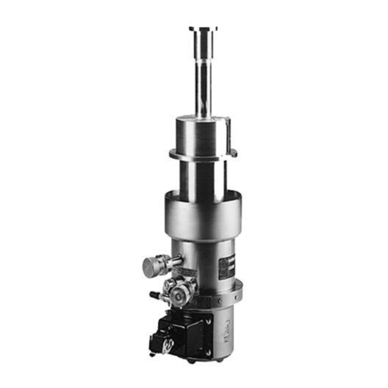
140 T and COOLPOWER 50 generate in connection with a compressor unit “cryogenic” temperatures, i.e. temperatures below 120 K (K = Kelvin). The COOLPOWER 5/100 (T) and 7/25 units are of a two-stage design, the COOLPOWER 140 T and 50 are of a single-stage design. - Page 8 (Flange for Part Nos. 893 04 and 842 030) 8 Control valve 9 Synchronous motor 10 Helium high-pressure connection 11 Safety valve 12 Helium low-pressure connection Fig. 1 Two-stage Gifford-McMahon cold head COOLPOWER 5/100 (Part No. 893 05; schematic diagram) GA12119_002_A3 - 01/2012 - © Oerlikon Leybold Vacuum...
-
Page 9: Technical Data
State of delivery; for filling pressure during operation refer to the Operating Instructions for the compressor unit. f = female coupling, m = male coupling; Type „Aeroquip series 5400“ or compatible types GA12119_00_A3 - 01/2012 - © Oerlikon Leybold Vacuum... - Page 10 State of delivery; for filling pressure during operation refer to the Operating Instructions for the com- pressor unit. f = female coupling, m = male coupling; Type „Aeroquip series 5400“ or compatible types GA12119_002_A3 - 01/2012 - © Oerlikon Leybold Vacuum...
-
Page 11: Ordering Data
842050V0000 Cold head COOLPOWER 140 T 842 030 Other flanges upon request Compressor units for COOLPOWER 5/100 T and 140 T COOLPAK 6000-H 400 V, 50 Hz, 3ph, 470 V, 60 Hz, 3ph 840000V6001 COOLPAK 6200-H 200 V... - Page 12 13,5 ° 13,5 ° 128,7 128,7 COOLPOWER 5/100, Part No. 893 05 COOLPOWER 5/100, Part No. 893 04 COOLPOWER 5/100 T, Part No. 129 78 Dimensional Drawing , dimensions in mm Fig. 2a GA12119_002_A3 - 01/2012 - © Oerlikon Leybold Vacuum...
- Page 13 M4x7 DN 160 ISO-K Ø 105 ca. 121 22.5° 45° Mid of clamp Heli-Coil M4, 7 deep Ø 60 COOLPOWER 140 T COOLPOWER 7/25 Dimensional Drawing , dimensions in mm Fig. 2b GA12119_00_A3 - 01/2012 - © Oerlikon Leybold Vacuum...
- Page 14 Description ø 87 ø69 ø 69 Gewinde M2 thread M2 27° COOLPOWER 50, Cat. No. 842050V0000 COOLPOWER 50, Cat. No. 842050V0001 Dimensional Drawing , dimensions in mm Fig. 2c GA12119_002_A3 - 01/2012 - © Oerlikon Leybold Vacuum...
-
Page 15: Transportation And Storing
(such as the original packaging) for storage and shipment. The cold head must not be picked up by the second cooling stage for shipment. It can be handled at the motor and the connection flange. GA12119_00_A3 - 01/2012 - © Oerlikon Leybold Vacuum... -
Page 16: Installation
The cold head must only be operated with the compressors, pressure lines and electric connecting lines specified for it. Connecting other components requires prior approval by Oerlikon Leybold Vacuum. 3.1.1 Non-conforming utilization Non-conforming utilizations for the cold head are among others: Safety devices must not be disabled. -
Page 17: Unpacking And Checking The Delivery
If the damaged part has to be replaced, please get in touch with Oerlikon Leybold Vacuum. In order to prevent the formation of condensate, leave the cold head to warm up to room temperature before installing it. GA12119_00_A3 - 01/2012 - © Oerlikon Leybold Vacuum... -
Page 18: Connecting The Cold Head
We will 5 ·1 0 gladly be of assistance in selecting a suitable vacuum pump. NOTICE Do not interchange the high-pressure- with the low-pressure connections. Wrong connection may damage the cold head. GA12119_002_A3 - 01/2012 - © Oerlikon Leybold Vacuum... -
Page 19: Electrical Connection
Please note the safety information given in Section 0.2. Before connecting the electrical connection cable, check to ensure that the compressor unit is set for the correct line voltage. Refer to the compressor unit operating instructions for details. GA12119_00_A3 - 01/2012 - © Oerlikon Leybold Vacuum... -
Page 20: Installing The Flexible Pressure Lines
28 bar. Do not twist the pressure lines. When fixing the screw fittings, use one wrench for tightening and a second wrench for countering; see Figs. 5 and 6. GA12119_002_A3 - 01/2012 - © Oerlikon Leybold Vacuum... - Page 21 If flexible pressure lines need to be routed with bending radii less than 30 cm, install 90° elbows; see Section 1.4 To extend the helium pressure lines, use line couplings; see Section 1.4. Bundle the flexlines and protect these against tripping and damage. GA12119_00_A3 - 01/2012 - © Oerlikon Leybold Vacuum...
- Page 22 28 bar (406 psig; 2.8 MPa). See Section 4.1 for details. Detach the flexlines by unscrewing the couplings in reverse order. Once they have been detached, fit protective caps on the couplings. GA12119_002_A3 - 01/2012 - © Oerlikon Leybold Vacuum...
-
Page 23: Operation
12 W ± 10% Maximum Permissible Cold-Head Temperature The temperature of the cold head must not exceed 50 °C at the refrigerating stages. Higher temperatures may damage components inside the cold head. GA12119_00_A3 - 01/2012 - © Oerlikon Leybold Vacuum... -
Page 24: Removing From Service
28 bar (406 psig; 2.8 MPa) operating pressure. All the self-sealing couplings which are not in use shall be provided with protective caps. GA12119_002_A3 - 01/2012 - © Oerlikon Leybold Vacuum... -
Page 25: Maintenance
Maintenance We recommend installing a complete, new displacer piston after 9,000 hours of operation. This job can only be performed by Oerlikon Leybold Vacuum Service or appropriately trained service personnel. Oerlikon Leybold Vacuum Oerlikon Leybold Vacuum offers practical seminars in which simple main-... -
Page 26: Troubleshooting
Trained personnel dirty. only. External magnetic field exists Reduce the magnetic field or shield the Trained personnel (> 30 mT=300 Gauß). cold head motor and then install a new only. cold-head motor. GA12119_002_A3 - 01/2012 - © Oerlikon Leybold Vacuum... -
Page 27: Waste Disposal
The cold head may have been contaminated by the process or by Contamination environmental influences. In this case the equipment must be decontami- nated in accordance with the relevant regulations. Oerlikon Leybold Vacuum offers this service at fixed prices. Further details are available on request. CAUTION Contaminated parts can be detrimental to health and environment. -
Page 28: Ec Incorporation Declaration
GA12119_002_A3 - 01/2012 - © Oerlikon Leybold Vacuum... -
Page 29: Ec Declaration Of Conformity
GA12119_00_A3 - 01/2012 - © Oerlikon Leybold Vacuum... -
Page 30: Declaration Of Contamination
I / we hereby declare that the information supplied on this form is accurate and sufficient to judge any contamination level. Name of authorized person (block letters) : Date signature of authorized person firm stamp 17200001_002_A1 © Oerlikon Leybold Vacuum GA12119_002_A3 - 01/2012 - © Oerlikon Leybold Vacuum... - Page 31 Notes GA12119_00_A3 - 01/2012 - © Oerlikon Leybold Vacuum...
- Page 32 Sales and Service Germany Europe Asia Netherlands P.R. China Japan Belgium Oerlikon Leybold Vacuum GmbH Oerlikon Oerlikon Oerlikon Oerlikon Bonner Strasse 498 Leybold Vacuum Nederland B.V. Leybold Vacuum (Tianjin) Leybold Vacuum Leybold Vacuum Nederland B.V. D-50968 Cologne Proostwetering 24N International Trade Co. Ltd. Japan Co., Ltd.
Need help?
Do you have a question about the COOLPOWER 5/100 and is the answer not in the manual?
Questions and answers