Table of Contents
Advertisement
We,
Hisense(Shandong) Air-conditioning Co.,Ltd.
No.8 Ronggang Road, Ronggui, Shunde,Foshan, Guangdong, P.R.China
No.1 Hisense Road, Nancun, Pingdu,Qingdao, Shandong Province, P.R.China
declare under our sole responsibility that the product
to which this declaration relates is in conformity with the technical requirements of the
following standard(s)
EMC Directive- 2014/30/EU
Low Voltage Directive-2014/35/EU
CE Marking Directive-93/68/EEC
LVD standard
EN 60335-1:2012+A11:2014
EN 60335-2-40:2003
+A11:2004+A12:2005+A1:2006+A2:2009
+A13:2012
EN 62233:2008
Hisense International Co., Ltd
( Supplier Address & Factory Address )
AIR CONDITIONER
(Category Name)
GBF18H-S
GDF18H-S
GBF24H-S
GDF24H-S
GBF36H-S
GDF36H-S
GBF48H-S
GDF48H-S
GBF60H-S
GDF60H-S
(Model Name)
GFF18H-S
GCF18H-S
GFF24H-S
GCF24H-S
GFF36H-S
GCF36H-S
GFF48H-S
GCF48H-S
GFF60H-S
GCF60H-S
EMC standard
EN 55014-1:2006
+A1:2009+A2:2011
EN 55014-2:1997 +A1:2001+A2:2008
EN 61000-3-2:2014
EN 61000-3-2:2014
EN 61003-3-3:2013
Advertisement
Table of Contents

Related Manuals for Hisense AUD-18HX4SNL


Summarization of Contents
1. GENERAL
1-1 Features
Overview of product features like save installation space and timer functions.
1-2 Product Lineup
Lists the available product types and models within the series.
1-3 MODEL IDENTIFICATION
Explains the naming convention for product models.
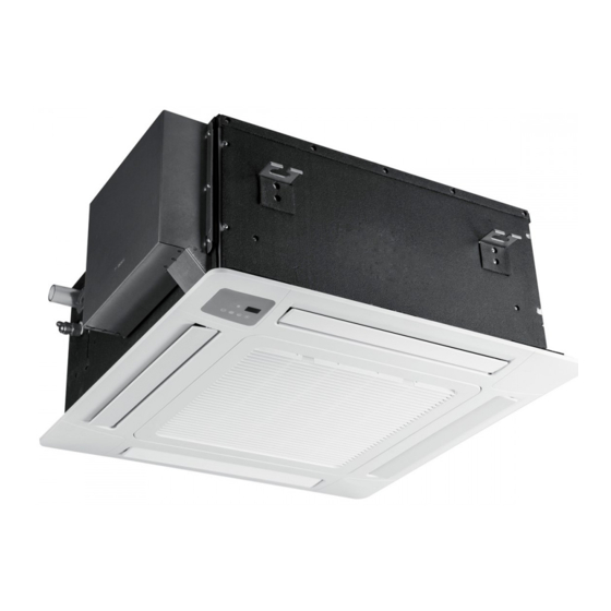
1-4 Product Picture
Visual representation of different product types (Duct, Cassette, Ceiling/Floor).
DISPLAY PANEL
Details the indicators and symbols on the unit's display panel.
2. SPECIFICATIONS
2.1 Duct Type
Technical specifications for Duct Type air conditioners.
2.2 Cassette Type
Technical specifications for Cassette Type air conditioners.
2.3 Ceiling&Floor type
Technical specifications for Ceiling & Floor Type air conditioners.
2.5 On/Off Unitary Universal Outdoor Unit
Technical specifications for outdoor units.
3. OUTLINES AND DIMENSIONS
3.1 INDOOR UNIT
Installation dimensions and outlines for indoor units (Duct, Cassette, Ceiling/Floor).
3-2.OUTDOOR
Installation dimensions and outlines for outdoor units.
4. DIAGRAM&DATA
4.1 Piping Diagrams
Schematic diagrams illustrating refrigerant piping for different models.
4.2MAX. Refrigerant pipe length and height difference
Guidelines for maximum refrigerant pipe length and height differences.
4.3ELECTRIC Diagrams
Wiring diagrams for indoor and outdoor units.
4-4Air flow and ESP Chart Diagrams(for duct type)
Airflow performance curves for Duct Type units at different ESPs.
4-5 Performance curve
Cooling and heating performance curves based on outdoor temperature.
5. ELECTRICAL DATA
5-1.Electrical wiring diagrams
Detailed electrical wiring diagrams for various unit types and models.
5-2. CONTROL BOARD
Identification of components on indoor and outdoor control boards.
5-3. Dip Switch Setting
Configuration settings using dip switches for different unit functions.
5-4 Static Pressure Setting(only for duct type)
Instructions for setting static pressure for duct type units.
5-5. System Parameter Adjustment
Guide to adjusting internal control system parameters.
5-6. Sensor parameter
Data tables for temperature sensors (NTC thermistors) at various temperatures.
6. CONTROL MODE
6-1 Indoor control mode
Detailed explanation of indoor unit control functions and parameters.
7. TROUBLE SHOOTING
HOW TO CHECK FAULT CODES
Procedures for checking error codes on different unit types and displays.
2.OUTDOOR UNIT FAULT CODE DISPLAY
Fault code indicators for outdoor units via lamps and digital displays.
3.Fault code display ( Driver Board )
Fault code display methods related to the driver board.
Analysis of the Driving Board Fault
Troubleshooting guide for driver board fault codes based on LED indicators.
Ii: Driver board fault codes trouble shooting(ONLY FOR 20K&16K DUAL TYPES)
Troubleshooting for driver board fault codes specific to 20K & 16K dual types.
8. CHECKING COMPONENTS
8-1. Check refrigerant system
Procedure for checking the refrigerant system flow and pressure.
8-2.Check parts unit
Procedures for examining and repairing indoor fan motors.
2. OUTDOOR FAN MOTOR
Procedures for examining and repairing outdoor fan motors.
3. COMPRESSOR
Procedures for examining and repairing compressors.
4. INDUCTANCE
Testing procedure for inductance, likely for motors or coils.
5. STEP MOTOR
Testing procedure for step motors.
6. FUSE
Procedure for checking fuse continuity on PCB ASS'Y.
7.CAPACITOR
Procedure for testing capacitor functionality using a multimeter.
Need help?
Do you have a question about the AUD-18HX4SNL and is the answer not in the manual?
Questions and answers