Sign In
Upload
Manuals
Brands
Kontron Manuals
Control Unit
EPIC/CE
User Manuals: Kontron EPIC/CE EPIC Board
Manuals and User Guides for Kontron EPIC/CE EPIC Board. We have
1
Kontron EPIC/CE EPIC Board manual available for free PDF download: User Manual
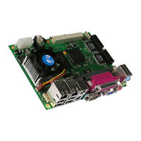
Kontron EPIC/CE User Manual (101 pages)
Brand:
Kontron
| Category:
Control Unit
| Size: 1 MB
Table of Contents
Table of Contents
3
1 User Information
9
About this Document
9
Copyright Notice
9
Trademarks
9
Standards
9
Warranty
9
Technical Support
10
2 Introduction
11
Epic/Ce
11
The EPIC Family
11
3 Getting Started
12
4 Specifications
13
Functional Specifications
13
Mechanical Specifications
15
PC/104 Bus Connector (ISA Part)
15
PC/104-Plus Bus Connector (PCI Part)
15
Dimensions
15
Height on Top
15
Height on Bottom
15
Weight
15
Electrical Specifications
16
Supply Voltages
16
Supply Voltage Ripple
16
Supply Current (Typical)
16
Supply Current (Maximum)
17
Real-Time Clock (RTC) Battery
17
Mtbf
18
Environmental Specifications
19
Temperature
19
Humidity
19
5 CPU, Chipset and Super I/O
20
Cpu
20
Chipset
20
GMCH (815E Chipset)
20
Ich4 (82801Db)
22
Super I/O
23
CPU, Chipset and Super-I/O Configuration
23
6 System Memory
24
7 ISA and PCI Bus Expansion
25
PC/104 Bus (ISA Part)
25
PC/104 Connectors
25
PC/104 Configuration
25
PC/104-Plus (PCI Part)
26
PC/104-Plus Connector
26
PC/104-Plus Configuration
26
8 Keyboard and Mouse Interfaces
27
PS/2-Keyboard Connector
27
PS/2-Keyboard Configuration
27
PS/2-Mouse Connector
27
PS/2-Mouse Configuration
28
9 USB Interfaces
29
Front Connectors (USB 0 to USB 3)
29
Internal Connectors (USB 4 and USB 5)
29
Limitations of USB Ports 4 and 5
30
Configuration
30
10 Ethernet Interfaces
31
First Ethernet Controller
31
Second Ethernet Controller
32
Connectors
32
Configuration
33
Ethernet Technical Support
33
11 Graphics Interfaces
34
Video Controller
34
CRT Connector
34
DVO Connector (Optional)
35
Flat Panel LVDS Interface (JILI) Connector
35
Display Power Considerations
36
Connecting a LCD Panel
36
Configuration
37
Graphics Technical Support
37
Available Video Modes
37
Standard IBM-Compatible VGA Modes
37
Extended VESA VGA Modes
38
12 Serial-Communication Interfaces
39
Serial Ports COM a to COM D
39
Connectors
39
Connector
40
Configuration
40
13 Parallel-Port Interface
41
Connector
41
Configuration
41
14 IDE Interfaces
42
Connector
42
Compactflash Socket
43
Configuration
43
15 Floppy Interface
44
Connector
44
Connector Diagram
45
Configuration
45
16 Sound Interface
46
Connectors
46
Jack Connector
46
Line-In/Rear Speakers Connector
47
Configuration
47
Technical Support for Sound
48
17 General Purpose Inputs/Outputs
49
Connector
49
Programming
50
16-Bit Operating Systems
50
32-Bit Operating Systems
52
Configuration
52
18 FAN Interface
53
Connector
53
Configuration
53
19 Power Interface
54
Power Interface Connectors
54
ATX Connector Version
54
Only Power Supply on ATX Connector
55
AT Connector Version
55
Configuration
55
Atx/Reset/2Led Interface
56
Configuration
56
20 Watchdog Timer
57
Configuration
57
Programming
57
Initializing the WDT
57
Triggering the WDT
57
21 Hardware Monitor
58
Configuration
58
22 Important Technology Information
59
Thermal Control
59
Thermal Management
59
ACPI Thermal Management
59
Processor Clock Throttling
60
I/O APIC Vs. 8259 PIC Interrupt Mode
60
Native Vs. Compatible IDE Mode
61
Compatible IDE Mode
61
Native Mode
61
Native Mode Configuration
61
23 Appendix A: System-Resource Allocation
62
Interrupt Request (IRQ) Lines
62
Direct Memory Access (DMA) Channels
63
Memory Map
64
Using Expanded Memory Managers
64
I/O Address Map
65
Peripheral Component Interconnect (PCI) Devices
66
SM Bus Devices
66
24 Appendix B: BIOS Operation
67
Determining the BIOS Version
67
Configuring the System BIOS
67
General Information
68
Main Menu
69
Master or Slave Submenus
70
Advanced Menu
71
Advanced Chipset Control Submenu
71
PCI/PNP Configuration Submenu
71
PCI Device, Slot #X Submenu
72
PCI/PNP ISA IRQ Resource Exclusion Submenu
72
Memory Cache Submenu
73
I/O Device Configuration Submenu
74
Keyboard Features Submenu
75
Hardware Monitor Submenu
75
Watchdog Timer Settings Submenu
75
Display Control Submenu
76
Miscellaneous Submenu
77
Security Menu
78
Power Menu
79
ACPI Resume Events
79
ACPI Control Submenu
81
Thermal Management Submenu
81
Boot Menu and Utilities
82
Multiboot XP
82
Boot First Function
83
Exit Menu
84
Kontron BIOS Extensions
84
JIDA BIOS Extension
85
Remote Control Client Extension
85
Lan Pxe Rom
85
Updating or Restoring BIOS Using Phoenixphlash
85
Flashing a BIOS
86
Preventing Problems When Updating or Restoring BIOS
87
25 Appendix C: Block Diagram
88
26 Appendix D: Mechanical Dimensions
89
Board Dimensions and Mounting Holes
89
Top View
89
Front View
89
Connector Locations (Pin 1)
90
Slot Dimensions
91
Front and Top View
91
27 Appendix E: Connector Layout
92
Top Side
92
Bottom Side
93
Connector Functions and Interface Cables
94
Pin-Out Table
96
28 Appendix F: PC Architecture Information
99
Buses
99
ISA, Standard PS/2 - Connectors
99
Pc/104, Pci
99
General PC Architecture
99
Ports
100
Serial
100
Ata
100
Usb
100
Programming
100
29 Appendix G: Document Revision History
101
Advertisement
Advertisement
Related Products
Kontron ETX-LX2
Kontron EPIC/PM
Kontron ePCI-101
Kontron ePanel-mgx
Kontron ePanel-C3
Kontron ECX-BYT
Kontron EZ3-VX3030 Series
Kontron EZ3-VX3030-00-L
Kontron KBox E-100 Series
Kontron EZ2-VX6060-00-L
Kontron Categories
Computer Hardware
Motherboard
Server
Industrial PC
Desktop
More Kontron Manuals
Login
Sign In
OR
Sign in with Facebook
Sign in with Google
Upload manual
Upload from disk
Upload from URL