Table of Contents
Advertisement
Quick Links
BEDIENUNG UND INSTALLATION
OPERATION AND INSTALLATION
UTILISATION ET INSTALLATION
BEDIENING EN INSTALLATIE
ANVÄNDNING OCH INSTALLATION
OBSLUHA A INSTALACE
OBSŁUGA I INSTALACJA
KEZELÉS ÉS TELEPÍTÉS
ЭКСПЛУАТАЦИЯ И МОНТАЖ
KÄYTTÖ JA ASENNUS
Warmwasser-Standspeicher für Wärmepumpen | Floorstanding DHW cylinder for heat
pumps | Ballon d'eau chaude sanitaire sur socle pour pompes à chaleur | Staande
warmwaterboiler voor warmtepompen | Stående ackumulatortank för varmvatten
för värmepumpar | Stojatý zásobník teplé vody pro tepelná čerpadla | Stojący
zasobnik c.w.u do pomp ciepła | Álló melegvíztartály hőszivattyúkhoz | Напольный
накопительный водонагреватель для тепловых насосов | Lattiamalliset lämminvesivaraajat
lämpöpumpuille
» SBB 300 WP Trend
» SBB 400 WP Trend
» SBB 500 WP Trend
Advertisement
Table of Contents
Troubleshooting

Related Manuals for STIEBEL ELTRON SBB 300 WP Trend


Summary of Contents for STIEBEL ELTRON SBB 300 WP Trend
- Page 1 | Stojatý zásobník teplé vody pro tepelná čerpadla | Stojący zasobnik c.w.u do pomp ciepła | Álló melegvíztartály hőszivattyúkhoz | Напольный накопительный водонагреватель для тепловых насосов | Lattiamalliset lämminvesivaraajat lämpöpumpuille » SBB 300 WP Trend » SBB 400 WP Trend » SBB 500 WP Trend...
-
Page 2: Table Of Contents
CONTENTS | OPERATION General information OPERATION OPERATION General information ��������������������������������������� 13 Safety instructions ���������������������������������������������� 13 Other symbols in this documentation ���������������������� 13 General information Units of measurement ����������������������������������������� 14 Safety �������������������������������������������������������� 14 The chapter "Operation" is intended for appliance users and qual- Intended use �����������������������������������������������������... -
Page 3: Units Of Measurement
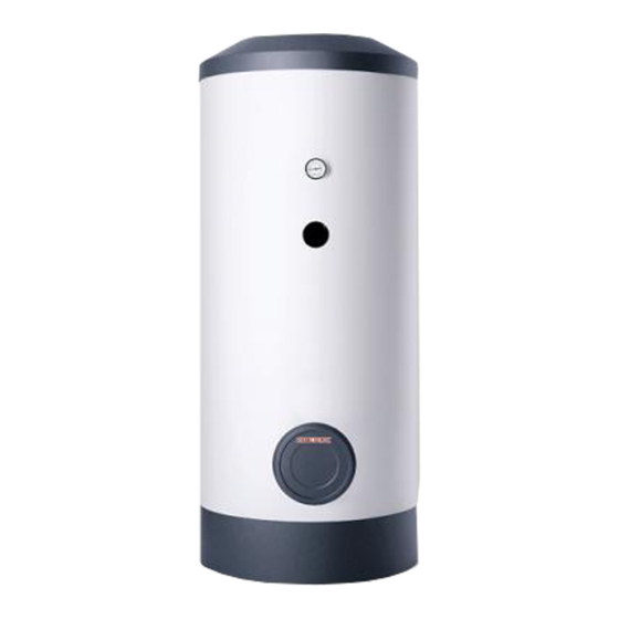
OPERATION Safety Appliance description Symbol Meaning Material losses (appliance damage, consequential losses and environmen- The DHW is heated via a smooth tube internal indirect coil. In tal pollution) addition, a threaded immersion heater can be connected. You Appliance disposal can use the appliance to supply one or several draw-off points. The appliance is equipped with an inspection flange and ther- mometer. -
Page 4: Installation
INSTALLATION Safety INSTALLATION Minimum clearances The minimum side clearances can be swapped to left or right. Safety Only a qualified contractor should carry out installation, commis- sioning, maintenance and repair of the appliance. General safety instructions ≥800 ≥300 We can only guarantee trouble-free function and operational reli- ability if original spare parts intended for the appliance are used. -
Page 5: Installation
INSTALLATION Installation Installation DHW line Copper or plastic are approved materials for pipework. Removing / fitting the cylinder casing Material losses If a threaded immersion heater is fitted and plastic pipe- Note work systems are used at the same time, observe the Open or remove the cylinder casing before fitting the DHW maximum permissible temperature and the maximum circulation and indirect coil lines. -
Page 6: Commissioning
INSTALLATION Commissioning 10. Commissioning 13. Maintenance 10.1 Initial start-up WARNING Electrocution Carry out all electrical connection and installation work f Open a downstream draw-off point until the appliance has in accordance with relevant regulations. filled up and the pipes are free of air. f Vent the internal indirect coil. -
Page 7: Specification
INSTALLATION Maintenance 14. Specification 14.1 Dimensions and connections SBB 300 WP Trend SBB 300 WP Trend Cold water inlet Male thread G 1 A DHW outlet Male thread G 1 A DHW circulation Male thread G 1/2 A Heat pump flow... - Page 8 INSTALLATION Maintenance SBB 400 WP Trend SBB 400 WP Trend Cold water inlet Male thread G 1 A DHW outlet Male thread G 1 A DHW circulation Male thread G 1/2 A Heat pump flow Female thread G 1 1/2 Heat pump return Female thread G 1 1/2...
- Page 9 INSTALLATION Maintenance SBB 500 WP Trend SBB 500 WP Trend Sectional view Cold water inlet Male thread G 1 A DHW outlet Male thread G 1 A DHW circulation Male thread G 1/2 A Heat pump flow Female thread G 1 1/2 Heat pump return Female thread G 1 1/2 h05 Sensor heat pump...
-
Page 10: Details On Energy Consumption
INSTALLATION | GUARANTEE | ENVIRONMENT AND RECYCLING Maintenance 14.2 Details on energy consumption The product data complies with EU regulations relating to the Directive on the ecological design of energy related products (ErP). SBB 300 WP Trend SBB 400 WP Trend SBB 500 WP Trend 233487... - Page 11 Deutschland Verkauf Tel. 05531 702-110 | Fax 05531 702-95108 | info-center@stiebel-eltron.de STIEBEL ELTRON GmbH & Co. KG Kundendienst Tel. 05531 702-111 | Fax 05531 702-95890 | kundendienst@stiebel-eltron.de Dr.-Stiebel-Straße 33 | 37603 Holzminden Ersatzteilverkauf Tel. 05531 702-120 | Fax 05531 702-95335 | ersatzteile@stiebel-eltron.de Tel.
Need help?
Do you have a question about the SBB 300 WP Trend and is the answer not in the manual?
Questions and answers