Table of Contents
Advertisement
Quick Links
Advertisement
Table of Contents

Subscribe to Our Youtube Channel
Related Manuals for Lumel NR30BAC


Summary of Contents for Lumel NR30BAC
- Page 1 RAIL MOUNTED POWER NETWORK METER NR30 USER’S MANUAL...
-
Page 2: Table Of Contents
Voltage inputs ..........................3 Connection of the meter ....................... 4 External connections diagram ...................... 5 COOPERATION WITH S4AO ......................8 NR30BAC PROGRAMMING ......................9 Frontal panel ..........................9 Messages after Switching the Supply on ................... 10 Starting operation ........................10 Language selection ........................ -
Page 3: Application
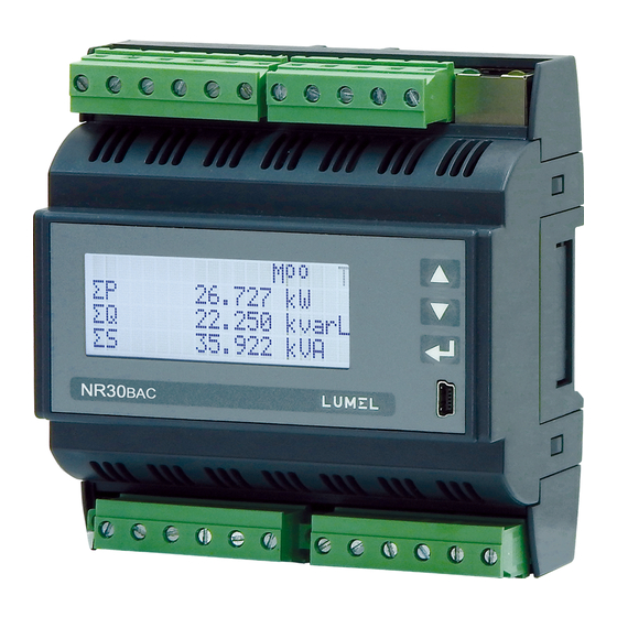
User's manual APPLICATION NR30BAC meter is a digital programmable instrument designed to measure network parameters of single-phase 2-wire and three-phase 3 and 4-wire balanced and unbalanced systems. The measured values are displayed on a 20 x 4 LCD character display. The meter enables controlling and optimizing the operation of power electronics devices, systems and industrial installations. -
Page 4: Installation
5.3 mm / indirect measurements/ and up to 16 ² /direct measurements. Fig.1. Overall dimensions of NR30BAC meter DESCRIPTION Current inputs All current inputs are galvanically isolated (internal current transformers). The meter is adapted for direct... -
Page 5: Connection Of The Meter
NR30BAC-09A User's manual Connection of the meter Description of the meter external terminals is shown in Fig 2. Fig.2. Connection of the meter: a) in the version for indirect connections (1 / 5 A) b) in the version for direct connections ( 63 A ) -
Page 6: External Connections Diagram
NR30BAC-09A User's manual External connections diagram Fig.3. Direct, semi-direct and indirect measurement in 1-phase network Fig.4. Direct measurement in 4-wire network version 63 A... - Page 7 NR30BAC-09A User's manual Direct measurement in 4-wire network Semi-indirect measurement in 4-wire network Indirect measurement in 4-wire network Fig.5. Input signal connection in 3-phase 4 - wire network...
- Page 8 NR30BAC-09A User's manual Direct measurement in 3 - wire network Semi-direct measurement using 2 current transformers in 3 - wire network. Indirect measurement using 2 current transformers and 2 or 3 voltage transformers in 3 - wire network. Fig.6. Input signal connection in 3-phase 3 - wire network...
-
Page 9: Cooperation With S4Ao
NR30BAC-09A User's manual COOPERATION WITH S4AO For NR30BAC versions with the S4AO block of 4 analog outputs, side connector for connecting blocks is included. The connector can also be ordered separately: order code 24-171-01-00016 NR30 connector Fig.7. Connecting blocks using the side connector Fig.8. -
Page 10: Nr30Bac Programming
NR30BAC-09A User's manual NR30BAC PROGRAMMING Frontal panel Fig.9. Frontal panel NR30BAC meter has 3 buttons and a 20 x 4 LCD character display. Description of the frontal panel: value increase key and moving up button to decrease the value and moving down... -
Page 11: Messages After Switching The Supply On
Messages after Switching the Supply on Starting operation When power is turned on, the meter displays the logo, NR30BAC meter name, version, current firmware version and MAC for versions with Ethernet, and then switches to measurement mode displaying the page which was set as the last one. Displayed information: Fig.11. -
Page 12: Language Selection
OPERATING MODES The NR30BAC meter has 9 operating modes: Measurement – normal operation mode. The values of quantities are displayed according to pre- programmed pages or pages configured by the user in the Displaying mode. - Page 13 NR30BAC-09A User's manual Fig.12b. Programming matrix Fig.12c. Programming matrix Fig.12d. Programming matrix...
-
Page 14: Measurement Mode
NR30BAC-09A User's manual Measurement mode In the Measurement mode, the values of quantities are displayed acc. to the pre-programmed or user- configured pages in the Displaying mode. The change of the page is done by pressing (next page) or button (previous page). -
Page 15: Parameters Mode
NR30BAC-09A User's manual Parameters mode Fig.15. Screen for selecting Parameters mode This mode is used to set the meter parameters. To enter the Parameters mode, press the button for approx. 3 seconds, and then press the select the Parameters mode and accept with the button . -
Page 16: Alarm Mode
"Voltage L - L", the parameter "Voltage L - N" is automatically converted ( x √3 ), For the configuration of NR30BAC meters you can also use our free eCon software available at www.lumel.com.pl Alarm mode Select the Alarms mode in options and approve the choice by pressing Fig.16. - Page 17 NR30BAC-09A User's manual Table 2 Parameter name range Notes / description Default value Logical conditions C1 v C2 v C3 C1 C2 C3 (C1 C2) vC3 (C1 vC2) C3 RLY state if AL on on/off State of relay with activated...
- Page 18 NR30BAC-09A User's manual State of condition State of condition Condition Condition fulfilled fulfilled Condition not met Condition not met Lower Upper Measured value Lower Upper Measured value condition condition condition condition value value value value State of condition State of condition...
-
Page 19: Display Mode
NR30BAC-09A User's manual Display mode In this mode, we configure the pages displayed in the normal operation mode of the meter Measurement, Fig.18. Ethernet mode screens Table 3 Parameter name range Notes / description Default value Backlight: On, off Display backlit... - Page 20 NR30BAC-09A User's manual Selection of the displayed quantities: Table 4 Sign Quantity name Designation Unit aling no quantity - display field is blank voltage of L1 phase (M,k)V current in phase wire L1 (k)A ...
- Page 21 NR30BAC-09A User's manual (M,k)V phase-to-phase voltage L2-L3 (M,k)V phase-to-phase voltage L3-L1 U123 (M,k)V phase-to-phase average voltage P DMD (G,M,k)W averaged active power (P Demand) S DMD (G,M,k)VA averaged apparent power (S Demand) I DMD ...
- Page 22 NR30BAC-09A User's manual Default settings of the displayed pages in 1-phase system Table 5c U1 V P1 W P DMD W P1 W Q1 var I1 A Q1 var S DMD W En P+ kWh En Q L kvarh f Hz...
- Page 23 NR30BAC-09A User's manual tgfactor of phase L3 THD U3 THD of voltage in phase L3** 100.00 [%] THD I3 THD of current in phase L3 100.00 [%] U avg Mean phase voltage 0.00 [%] I avg Mean 3-phase current In [A] * ΣP...
-
Page 24: Ethernet/ Bacnet Ip Mode
NR30BAC-09A User's manual Ethernet/ BACnet IP mode Select the Ethernet/ BACnet IP mode in options and approve the choice by the push-button. Fig.19. Ethernet mode screen Table 7 Parameter name range Notes / description Default value DHCP Off/on Enabling/Disabling DHCP Client... -
Page 25: Modbus Mode
NR30BAC-09A User's manual Modbus mode Select the Modbus mode in options and approve the choice by the push-button. Fig.20. Modbus mode screen Table 8 Parameter name Characteristic / value Description Default value 1…247 Address Address on the Modbus network. Baudrate... -
Page 26: Information Mode
NR30BAC-09A User's manual Information mode Select the Information mode in options and approve the choice by the push-button. Fig.24. Information mode screen Table 10 Parameter name Characteristic / Description Default value value Type Type of meter NR30BAC Order code First 5 digits of ordering code e.g.12200... -
Page 27: Serial Interfaces
SERIAL INTERFACES Ethernet/ BACnet IP INTERFACE The NR30BAC meters are equipped with a Fast Ethernet interface (100 Mb/s) enabling the meter connection (using the RJ45 socket) to the Ethernet network. The BACnet IP communication standard described in EN ISO 16484-5 was used. -
Page 28: Ethernet /Bacnet Ip Interface Connection
5 with RJ-45 connector with conductors colors (in accordance with the colors described in table 13) acc. to the following standard: • EIA/TIA 568A for both connectors at the so-called simple connection of NR30BAC to the network hub or switch, •... -
Page 29: Rs485 Interface - The List Of Parameters
NR30BAC-09A User's manual RS485 INTERFACE – the list of parameters The implemented protocol is in accordance with the PI-MBUS-300 Rev G of Modicon Company. The list of serial link parameters of NR30BAC meter: ID 0xE6 meter address 1..247, ... - Page 30 NR30BAC-09A User's manual Response: Device Number of Value from Value from Value from Value from Checksum address Function bytes the register the register the register the register 1B58 (7000) 1B59 (7001) 1B5A (7002) 1B5B (7003) E4 6F Example 3 . Readout of 2 32-bit registers of float type as a combination of 2 16-bit registers starting with the register addressed 1770h (6000) - registers values 10, 100.
- Page 31 NR30BAC-09A User's manual Readout of single register (code 06h) Example 5. Record of 543 (0x021F) value to register 4000 (0x0FA0) Request: Checksum CRC Device Register address Register value address Function CA 54 Response: Device Register address Register value Checksum CRC...
-
Page 32: Meter Data Structure
User's manual 10 METER DATA STRUCTURE In the NR30BAC meter, data can be read using the BACnet IP protocol by reading the properties of individual objects configured in the device. Data can also be read via the RS485 interface and Modbus protocol by reference to individual registers. - Page 33 NR30BAC-09A User's manual THD U3(U31) THD U3* THD I3 THD I3 Uavg Average 3-phase voltage Iavg Average 3-phase current 3-phase active power (P1+P2+P3) 3-phase reactive power (Q1+Q2+Q3) 3-phase apparent power (S1+S2+S3) 3-phase active power factor (PF=P/S) tg factor 3-phase average (tg=Q/P)
- Page 34 NR30BAC-09A User's manual U1_min Voltage L1 min U1_max Voltage L1 max U2_min Voltage L2 min U2_max Voltage L2 max U3_min Voltage L3 min U3_max Voltage L3 max I1_min Current L1 min I1_max Current L1 max I2_min Current L2 min I2_max...
- Page 35 NR30BAC-09A User's manual U23_min Phase-to-phase voltage L U23_max Phase-to-phase voltage L U31_min Phase-to-phase voltage L U31_max Phase-to-phase voltage L Uavg_min Average 3-phase voltage min Uavg_max Average 3-phase voltage max Iavg_min Average 3-phase current min Iavg_max Average 3-phase current max 3P_min...
-
Page 36: Register Structure For Rs485 / Modbus Interface
10.2 Register structure for RS485 / Modbus interface In the NR30BAC meter, data are placed in 16 and 32-bit registers. Process variables and meter parameters are placed in the address area of registers in a way depended on the variable value type. - Page 37 NR30BAC-09A User's manual Table 15 Address range Value type Description Integer Value set in the 16-bit register. Registers for meter configuration. Descrip- 4000 – 4159 (16 bits) tion of registers is shown in Table 17. Registers for writing and readout.
- Page 38 NR30BAC-09A User's manual Voltage on terminal 5 0 - first L1 phase voltage 4003 0 .. 2 1 - second L2 phase voltage 2 - third L3 phase voltage Voltage on terminal 8 0 - first L1 phase voltage 4004 0 ..
- Page 39 NR30BAC-09A User's manual 1000 .. 1700 V 1000 or 4019 Phase-to-phase input voltage x10 4000 4000 .. 6900 V 4020 reserved 4021 reserved 4022 reserved 4023 reserved Energy counters erasing 0 – no changes, 1 – erase active energies 0…4 4024 2 –...
- Page 40 NR30BAC-09A User's manual Alarm output 1 - type for the condition 2: 0 – n_on, 1 – noFF, 2 – on, 3 – oFF, 4 – H_on, 5 – HoFF, 6 – 3non, 4044 0..9 7 – 3noF, 8 – 3_on, 9 – 3_oF Alarm output 1 - lower value of the condition 2 switch of -1440..0..1440...
- Page 41 NR30BAC-09A User's manual Alarm output 2 - upper value of the condition 1 switch of -1440..0..1440 4068 1100 the rated input range 4069 0..3600 s Alarm output 2 - condition 1 activation delay 4070 0..3600 s Alarm output 2 - condition 1 deactivation delay 4071 0..3600 s...
- Page 42 NR30BAC-09A User's manual 4095 reserved 4096 reserved 4097 reserved 4098 reserved 4099 reserved 4100 1..247 Modbus Network Address 4101 0..3 Transmission mode: 0->8n2, 1->8e1, 2->8o1, 3->8n1 Baud rate: 0->4800, 1->9600 4102 0..5 2->19200, 3->38400, 4->57600, 5->115200 4103 reserved 4104 Upgrade change of transmission parameters...
- Page 43 NR30BAC-09A User's manual 4140 reserved Baud rate of the Ethernet interface: 0 – automatic selection of the baud rate 4141 0 .. 2 1 – 10 Mb/s 2 – 100 Mb/s 4142 20...65535 FTP server command port number 4143 20...65535...
- Page 44 NR30BAC-09A User's manual Table 17 Register Operations Range Description Default address 4200 7500 .. 7957 Register 1 of programmable group of registers for readout 7500 4201 7500 .. 7957 Register 2 of programmable group of registers for readout 7501 4202 7500 ..
- Page 45 NR30BAC-09A User's manual Register Operations Range Description Default address 4232 7500 .. 7957 Register 33 of programmable group of registers for readout 7532 4233 7500 .. 7957 Register 34 of programmable group of registers for readout 7533 4234 7500 .. 7957...
- Page 46 NR30BAC-09A User's manual Table 18 16-bit register address Register address Operations Description 2x16 1032/ 32-bit 2x16 3210 7200/7000 7400 Content of the register set in the registers 4200 7202/7002 7401 Content of the register set in the registers 4201 7204/7004...
- Page 47 NR30BAC-09A User's manual 7262/7062 7431 Content of the register set in the registers 4231 7264/7064 7432 Content of the register set in the registers 4232 7266/7066 7433 Content of the register set in the registers 4233 7268/7068 7434 Content of the register set in the registers 4234...
- Page 48 NR30BAC-09A User's manual Table 19 Register Operations Range Description Default address Luminosity: 0 – Off, 1- On 4300 0…1 4301 0 .. 3600 Time to min. luminosity 4302 reserved Enabling page display Bit0 – page 1, 0xFFFF 4303 0x0001...0xFFFF Bit1 – page 2, ...Bit15 – page 16 Enabling page display Bit0 –...
- Page 49 NR30BAC-09A User's manual Register Operations Range Description Default address 4330 00...50 Page 9 display 2, I avg 4331 00...50 Page 9 display 3, I(N) 4332 00...50 Page 10 display 1, PFavg 4333 00...50 Page 10 display 2, tgavg 4334 00...50...
- Page 50 NR30BAC-09A User's manual Register Operations Range Description Default address 4363 00...50 Page 20 display 2, En S 4364 00...50 Page 20 display 3, f 4365 00...50 Page 21 display 1, TH U1 4366 00...50 Page 21 display 2, TH U2 4367 00...50...
- Page 51 NR30BAC-09A User's manual Table 20 Register Operations Range Description Default address 4400 reserved 4401 0..65535 Identifier 4402 0..65535 Bootloader version x 100 4403 0..65535 Program version x100 4404 reserved 4405 0..65535 Ordering codes 4406 0..65535 Nominal voltage x10 577/2300 4407 0..65535...
- Page 52 NR30BAC-09A User's manual 4428 0..152 Active export energy, two older bytes 4429 0..65535 Active export energy, two younger bytes 4430 0..152 Reactive inductive energy, two older bytes 4431 0..65535 Reactive inductive energy, two younger bytes 4432 0..152 Reactive capacity energy, two older bytes 4433 0..65535...
- Page 53 NR30BAC-09A User's manual two older bytes Active exported 3-phase energy for the current month, 4473 0..65535 two younger bytes Active imported 3-phase energy for the current week, 4474 0..152 two older bytes Active imported 3-phase energy for the current week, 4475 0..65535...
- Page 54 NR30BAC-09A User's manual Status 1 Register of a device (address 4415, R): Bit 15 – "1” – FRAM memory damage Bit 7 – "1” – phase sequence error Bit 14 – "1” – no calibration of the input Bit 6 – reserved Bit 13 –...
- Page 55 NR30BAC-09A User's manual Status 7 Register – (address 4424, R): Bit 8 ...0 – reserved Table 21 16-bit register Register address address Operations Description Unit 2x16 1032/ 32-bit 2x16 3210 6000/8000 7500 L1 phase voltage ...
- Page 56 NR30BAC-09A User's manual 6056/8056 7528 Mean 3-phase current 6058/8058 7529 3-phase active power (P1+P2+P3) 6060/8060 7530 3-phase reactive power (Q1+Q2+Q3) 6062/8062 7531 3-phase apparent power (S1+S2+S3) 6064/8064 7532 3-phase active power factor (PF=P/S) ...
- Page 57 NR30BAC-09A User's manual Time – seconds 6110/8110 7555 Time – hours, minutes 6112/8112 7556 Date – month, day 6114/8114 7557 Year – 2014 - 2100 6116/8116 7558 ...
- Page 58 NR30BAC-09A User's manual 6180/8180 7590 Reactive power L3 min 6182/8182 7591 Reactive power L3 max 6184/8184 7592 Apparent power L1 min 6186/8186 7593 Apparent power L1 max 6188/8188 7594 Apparent power L2 min ...
- Page 59 NR30BAC-09A User's manual 6250/8250 7625 3-phase apparent power (max) 6252/8252 7626 Power factor (PF) min 6254/8254 7627 Power factor (PF) max 6256/8256 7628 Reactive to active power ratio (3-phase mean min.) ...
- Page 60 NR30BAC-09A User's manual 6320/8320 7660 THD I min 6322/8322 7661 THD I max 6324/8324 7662 HarU1[2] 2nd harmonic of L1 phase voltage 6326/8326 7663 HarU1[3] 3rd harmonic of L1 phase voltage 6420/8420...
- Page 61 NR30BAC-09A User's manual 6920/8920 7960 Harl3[50] 50th harmonic of L3 phase current 6922/8922 7961 Harl3[51] 51st harmonic of L3 phase current 6924/8924 7962 Mean reactive power 6926/8926 7963 Mean reactive power min ...
- Page 62 NR30BAC-09A User's manual Active exported 3-phase energy for the current 6964/8964 7982 week (overflows number of register 7577, reset after 9999.9 MWh is reached) Active exported 3-phase energy for the current 6966/8966 7983 week (counter up to 9999.99 kWh) Active imported 3-phase energy for the current ...
-
Page 63: Firmware Upgrade
11. 1 Firmware upgrade - the main program of the meter NR30BAC meters have a feature that allows the user to upgrade the software using a PC with eCon software. Free eCon software and update files are available at www.lumel.com.pl. Upgrade of the meter software (firmware) can be done via the RS485 interface. -
Page 64: Error Codes
NR30BAC-09A User's manual 12 ERROR CODES During operation of the meter, error messages may appear on the display. The causes of the errors are listed below. Error: MEM_FR, CAL_IN – displayed when the memory of the meter is corrupted. The meter must be sent to the manufacturer. - Page 65 NR30BAC-09A User's manual Total harmonic distortion of voltage THDU, and current THDI • • • • 5 (EN 61557-12) 0.0 .. 100.0 % Amplitudes of voltage harmonics • • • ...U 0.0 .. 100.0 % II (IEC61000-4-7) … I and current I...
- Page 66 NR30BAC-09A User's manual Weight 0.3 kg Dimensions 105 x 110 x 60 mm Reference conditions and rated operating conditions. - power supply 85..253 V a.c. (40..50..400) Hz or 90..300 V d.c. or 20..40 V a.c. or 20..60 V d.c. - input signal: 0 ..
-
Page 67: Ordering Codes
* 4-channel S4AO analog output module will be made in English language version with the same power supply as the ordered NR30BAC meter, unless the customer specifies otherwise. The S4AO module communicates with the NR30BAC meter via the RS485 Modbus Master interface, therefore cooperation with S4AO excludes the use the NR30BAC meter RS485 interface for communication with another Master. - Page 68 LUMEL S.A. ul. Sulechowska 1, 65-022 Zielona Góra, Poland tel.: +48 68 45 75 100, fax +48 68 45 75 508 www.lumel.com.pl Export department: tel.: (+48 68) 45 75 139, 45 75 233, 45 75 321, 45 75 386 fax.: (+48 68) 32 54 091 e-mail: export@lumel.com.pl...
Need help?
Do you have a question about the NR30BAC and is the answer not in the manual?
Questions and answers