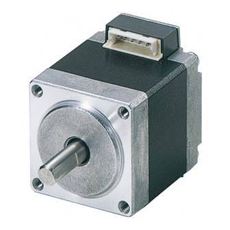
Oriental motor CRK Series User Manual
5-phase stepping motor and driver package
Hide thumbs
Also See for CRK Series:
- Operating manual (52 pages) ,
- Information (8 pages) ,
- Manual (4 pages)
Table of Contents
Advertisement
Quick Links
Download this manual
See also:
Operating Manual
5-phase stepping motor and driver package
CRK Series
Built-in Controller Type
USER MANUAL
R-REM-OMC-108
Thank you for purchasing an Oriental Motor product.
This Manual describes product handling procedures and safety precautions.
• Please read it thoroughly to ensure safe operation.
• Always keep the manual where it is readily available.
HM-40112-9
Introduction
Installation and
connection
Operation type and
setting
Method of control via I/O
Method of control via
Modbus RTU (RS-485
communication)
Method of control via
industrial network
Inspection,
troubleshooting and
remedial actions
Appendix
Advertisement
Table of Contents
Troubleshooting

Subscribe to Our Youtube Channel
Related Manuals for Oriental motor CRK Series


Summary of Contents for Oriental motor CRK Series
- Page 1 Appendix Thank you for purchasing an Oriental Motor product. This Manual describes product handling procedures and safety precautions. • Please read it thoroughly to ensure safe operation. • Always keep the manual where it is readily available.
-
Page 2: Table Of Contents
Introduction Introduction .................................. 8 Overview of the product ............................. 9 System configuration ..............................11 Safety precautions ..............................12 Precautions for use ..............................14 General specifications ...............................16 Regulations and standards ............................17 EU Directive ......................................17 Republic of Korea, Radio Waves Act ............................... 17 RoHS Directive ....................................... 17 Preparation ..................................18 Checking the product .................................. - Page 3 Operation type and setting Adjustment and setting ............................58 Step angle ........................................ 58 Operating current ....................................58 Standstill current ....................................59 Acceleration/deceleration rate ................................ 59 Operation ..................................60 Positioning operation..................................61 Return-to-home operation ................................70 Continuous operation ..................................75 Other operation ..................................... 77 Operation data ................................79 Parameter ..................................80 Parameter list......................................
- Page 4 Method of control via Modbus RTU (RS-485 communication) Guidance ..................................104 Communication specifications ..........................106 Setting the switches ..............................107 Setting the RS-485 communication ........................109 Communication mode and communication timing ..................110 Communication mode ..................................110 Communication timing ..................................110 Message ..................................111 Query ........................................111 Response ........................................113 Function code ................................115 Reading from a holding register(s) ...............................115 Writing to a holding register ................................116...
- Page 5 Method of control via MECHATROLINK communication ..................154 Guidance ........................................154 Setting the switches ..................................157 I/O field map for the NETC01-M2 ..............................158 I/O field map for the NETC01-M3 ..............................159 Communication format ..................................160 Details of remote I/O ...............................162 Input signals to the driver ................................162 Output signals from the driver ..............................162 Command code list ..............................164 Group function ....................................164...
- Page 7 Introduction This part explains the composition of the operating manuals, the product overview, specifications and safety standards as well as the name and function of each part and others. Table of contents Introduction ..........8 Overview of the product ......9 System configuration ......
-
Page 8: Introduction
Do not use for any other purpose. For the driver’s power supply, use a DC power supply with reinforced insulation on its primary and secondary sides. Oriental Motor Co., Ltd. is not responsible for any damage caused through failure to observe this warning. -
Page 9: Overview Of The Product
PC and driver. Be sure to purchase it. • OPX-2A ..This product can be purchased separately. „ Related products You can connect the CRK Series FLEX built-in controller via the network converter so as to use in various network. Network converter Supported network NETC01-CC CC-Link Ver.1.1... - Page 10 Overview of the product „ Function list Main functions • 2-sensor mode • Data setting mode (Position preset) Return-to-home operation • 3-sensor mode [Setting by parameters] • Positioning operation Operation function Starting method Motor operation Single-motion operation Data number selecting operation Linked-motion operation Sequential positioning operation [Setting by operation data...
-
Page 11: System Configuration
System configuration System configuration Master controller Connect master controller when controlling the system via RS-485 communication. Connect to CN6 or CN7. PC in which the MEXE02 OPX-2A has been installed * Connect to CN3. Connect to CN2. Encoder connection Connect a motor with an encoder if used. -
Page 12: Safety Precautions
RS-485 communication error occurs. Repair, disassembly and modification • Do not disassemble or modify the motor and driver. This may cause injury. Refer all such internal inspections and repairs to the Oriental Motor sales office from which you purchased the product. - Page 13 Safety precautions General • Do not use the motor and driver beyond its specifications. Doing so may result in injury or damage to equipment. • Keep your fingers and objects out of the openings in the motor and driver. Failure to do so may result in fire or injury.
-
Page 14: Precautions For Use
Precautions for use Precautions for use This section covers limitations and requirements the user should consider when using the product. z When conducting the insulation resistance measurement and the dielectric strength test, be sure to separate the connection between the motor and the driver. Conducting the insulation resistance measurement or dielectric strength test with the motor and driver connected may result in damage to the product. - Page 15 Precautions for use z Rotating direction of the gear output shaft The relationship between the rotating direction of the motor shaft and that of the gear output shaft changes as follows, depending on the gear type and gear ratio. Rotating direction (relative to the motor rotating direction) Frame size [mm (in.)] Type of gear Gear ratio...
-
Page 16: General Specifications
General specifications General specifications Motor Driver • High-resolution type • High-torque type IP20 • High-torque type with encoder • Geared type (CRK513P, CRK523P) • Standard type Degree of protection IP20 • Standard type with electromagnetic brake IP30 • Standard type with encoder •... -
Page 17: Regulations And Standards
Regulations and standards Regulations and standards EU Directive „ CE Marking z Low Voltage Directive Although this product is exempt from the Low Voltage Directive since the input power supply voltage is 24 VDC, perform the installation and connection as follows. •... -
Page 18: Preparation
This chapter explains the items you should check, as well as the name and function of each part. Checking the product Verify that the items listed below are included. Report any missing or damaged items to the Oriental Motor sales office from which you purchased the product. -
Page 19: Combinations Of Motors And Drivers
Preparation Combinations of motors and drivers Verify the model number of the purchased unit against the number shown on the package label. Check the model number of the motor and driver against the number shown on the nameplate. • The box ( ) in the model name indicates A (single shaft) or B (double shaft) •... - Page 20 Preparation „ Standard type with encoder Frame size [mm (in.)] Model Motor model Driver model CRK543RKD PK543AW-R23L 42 (1.65) CRK544RKD PK544AW-R23L CRD507-KD CRK545RKD PK545AW-R23L CRK564RKD PK564AW-R23L 60 (2.36) CRK566RKD PK566AW-R23L CRD514-KD CRK569RKD PK569AW-R23L „ Standard type with electromagnetic brake Frame size [mm (in.)] Model Motor model...
-
Page 21: Names And Functions Of Parts
Preparation „ PN geared type Frame size [mm (in.)] Model Motor model Driver model 28 (1.10) CRK523PAKD-N„ PK523PA-N„ CRD503-KD 42 (1.65) CRK544AKD-N„ PK544AW-N„ CRD507-KD CRK564AKD-N„ PK564AW-N„ 60 (2.36) CRD514-KD CRK566AKD-N„ PK566AW-N„ „ Harmonic geared type Frame size [mm (in.)] Model Motor model Driver model... - Page 22 Preparation „ Driver RS-485 communication connectors (CN6/CN7) POWER LED (green) Terminal resistor setting switch (SW3) ALARM LED (red) C-DAT LED (green) Data edit connector (CN3) C-ERR LED (red) Encoder connector (CN5) Address number setting switch (SW1) Function setting switch (SW2) Motor connector (CN4) I/O signals connector (CN2) Power supply connector (CN1)
-
Page 23: 2 Installation And Connection
Installation and connection This part explains the installation method of the product, the mounting method of a load and the connection method as well as I/O signals. Table of contents Installation ..........24 2-3 Connecting the electromagnetic brake ..............36 1-1 Location for installation ........ -
Page 24: Installation
Installation Installation This chapter explains the installation location and installation method of the motor and driver, and installing a load. Also covered in this section are the installation and wiring methods that are in compliance with the relevant EMC Directives. Location for installation The driver is designed and manufactured for installation in equipment. - Page 25 Installation „ Screw size, tightening torque and installation method • The box ( ) in the model name indicates A (single shaft) or B (double shaft). • For geared type, the box ( „ ) in the model name indicates a number of the gear ratio. Tightening Effective depth Frame size...
-
Page 26: Installing A Load
Installation Tightening Effective depth Frame size Installation Type Motor model Nominal size torque of screw thread [mm (in.)] method [N·m (oz-in)] [mm (in.)] PK564AWM Standard type with PK566AWM electromagnetic brake PK569AWM 2 (280) − PK564W Standard type PK566W PK569W 60 (2.36) TH geared PK564W-T„... -
Page 27: Permissible Radial Load And Permissible Axial Load
Installation Tightening torque Effective depth of screw thread Motor model Nominal size Number of screws [N·m (oz-in)] [mm (in.)] PK513 0.35 (49) 3 (0.118) PK523 1.4 (198) 4 (0.157) PK543 1.4 (198) 5 (0.20) PK564 2.5 (350) 6 (0.236) • When installing a load on the flange surface, the load cannot also be affixed using the keyway (or milled surface) in the output shaft. - Page 28 Installation Permissible radial load [N (lb.)] Distance from the tip of motor output Permissible Frame size Type Motor model Gear ratio shaft [mm (in.)] axial load [mm (in.)] [N (lb.)] (0.20) (0.39) (0.59) (0.79) High-resolution PK544PM„ − type PK546PM PK544P„ High-torque type −...
- Page 29 Installation Permissible radial load [N (lb.)] Distance from the tip of motor output Permissible Frame size Type Motor model Gear ratio shaft [mm (in.)] axial load [mm (in.)] [N (lb.)] (0.20) (0.39) (0.59) (0.79) (38) (45) (51) (60) (72) PK566W-PS„ (45) (49) (58)
-
Page 30: Installing The Driver
Installation Installing the driver „ Installation direction Mount the driver to a 35 mm (1.38 in.) width DIN rail. Provide 50 mm (1.97 in.) clearances in the horizontal and vertical directions between the driver and enclosure or other equipment within the enclosure. Refer to the figure for the required distances between adjacent drivers when two or more drivers are installed in parallel. -
Page 31: Installing And Wiring In Compliance With Emc Directive
The use of the following installation and wiring methods will enable the motor and driver to be compliant with the EMC directive. Refer to p.17 for the applicable standards. Oriental Motor conducts EMC measurements its motors and drivers in accordance with "Example of motor and driver installation and wiring" on p.32. - Page 32 Installation „ Notes about installation and wiring • Connect the motor, driver and other peripheral control equipment directly to the grounding point so as to prevent a potential difference from developing between grounds. • When relays or electromagnetic switches are used together with the system, use noise filters and CR circuits to suppress surges generated by them.
-
Page 33: Connection
Connection Connection This chapter explains how to connect the power supply, driver, motor, I/O signals as well as grounding method. For protection against electric shock, do not turn on the power supply until the wiring is completed. • Have the connector plugged in securely. Insecure connector connection may cause malfunction or damage to the motor or driver. -
Page 34: Connecting The Connector-Type Motor
Connection „ CN4 pin assignments Pin No. Connection destination Pin No. Blue motor lead Red motor lead Orange motor lead Green motor lead Black motor lead „ Composition of CN4 connector lead wires Connector housing 51103-0500 (Molex) Contact 50351-8000 (Molex) Crimping tool 63811-8100 (Molex) Applicable lead size... - Page 35 Connection „ Connector pin assignments of connector-type motor Pin No. Description Blue motor lead Red motor lead Orange motor lead Green motor lead Black motor lead Pin No. 5 4 3 2 1 „ Composition of motor connector lead wires Frame size [mm (in.)] ...
-
Page 36: Connecting The Electromagnetic Brake
Connection Connecting the electromagnetic brake „ Connecting the power supply for electromagnetic brake The electromagnetic brake operates via the ON/OFF status of the DC power supply. Provide a DC power supply of 24 VDC±5% 0.08 A or more for the CRK54, or 24 VDC±5% 0.25 A or more for the CRK56, for use exclusively for the electromagnetic brake. -
Page 37: Connecting The Power Supply And Grounding The Driver
Connection Connecting the power supply and grounding the driver Use the included CN1 connector (3 pins) to connect the power supply cable (AWG22: 0.3 mm ) to the power supply connector (CN1) on the driver. • When connecting, check the silk screen of the driver and pay attention to the polarity of the power supply. -
Page 38: Connecting The I/O Signals
Connection Connecting the I/O signals Connect the included CN2 connector cable (40 pins) to the I/O signals connector (CN2) on the driver. CN2 connector cable „ CN2 pin assignments Brown-1 (A1) • • Upper ribbon cable • • • Black-2 (A20) Brown-3 (B1) •... - Page 39 Connection „ Connecting to a current sink output circuit Controller Driver +24 VDC IN-COM0 4.4 kΩ 1 kΩ START 4.4 kΩ 1 kΩ ALM-RST 4.4 kΩ 1 kΩ 4.4 kΩ 1 kΩ STOP 4.4 kΩ 1 kΩ 4.4 kΩ 1 kΩ 4.4 kΩ...
- Page 40 Connection „ Connecting to a current source output circuit Controller Driver +24 VDC IN-COM0 4.4 kΩ 1 kΩ START 4.4 kΩ 1 kΩ ALM-RST 4.4 kΩ 1 kΩ 4.4 kΩ STOP 1 kΩ 4.4 kΩ 1 kΩ 4.4 kΩ 1 kΩ 4.4 kΩ...
-
Page 41: Connecting The Data Setter
Connection Connecting the data setter Connect the communication cable for the support software or OPX-2A cable to the data edit Communication cable for the support software or OPX-2A cable connector (CN3) on the driver. Data edit connector (CN3) The driver's power supply connector (CN1), I/O connector (CN2), data edit connector (CN3) and RS-485 communication connectors (CN6/CN7) are not electrically insulated. - Page 42 Connection z CN5 pin assignments Pin No. Signal name Description Connection destination Pin No.1 ENC-A+ Red encoder lead Encoder input A-phase (Line receiver) ENC-A− Pink encoder lead ENC-B+ Green encoder lead Encoder input B-phase (Line receiver) ENC-B− Blue encoder lead ENC-Z+ Yellow encoder lead Encoder input Z-phase...
- Page 43 Connection „ 20 mm, 28mm „ Connect with the included encoder connector lead wires. When extending the lead wires, use a shielded cable of AWG24 to 22 (0.2 to 0.3 mm Refer to p.86 for the detailed specification of this encoder. 1.
-
Page 44: Connecting The Rs-485 Communication Cable
Connection Connecting the RS-485 communication cable Connect this cable if you want to control your product Drivers can be linked. via RS-485 communication. Connect RS-485 communication cable to CN6 or CN7 on the driver. You can use the vacant connectors to connect a different driver. -
Page 45: Explanation Of I/O Signals
Explanation of I/O signals Explanation of I/O signals Input signals Following input signals of the driver are photocoupler inputs. The signal state represents the “ON: Carrying current” or “OFF: Not carrying current” state of the internal photocoupler. IN-COM0, START, ALM-RST, AWO, STOP M0 to M5, HOME/P-PRESET, FWD, RVS IN-COM1, +LS, -LS, HOMES, SLIT Driver internal circuit... - Page 46 Explanation of I/O signals „ STOP input The STOP input is used to stop the operating motor (factory setting: normally closed). The STOP input turns OFF, the motor will stop. This input is normally closed, meaning that it is OFF when the power is turned on.
- Page 47 Explanation of I/O signals z When the STOP stopping method is immediate stop + motor is not excited or deceleration stop + motor is not excited. 4 ms or more STOP input *1 0 ms or more 4 ms or more START input 6 ms or less *2 6 ms or less...
- Page 48 Explanation of I/O signals Operation Operation data No. data No. „ FWD input, RVS input When the FWD input turns ON, the motor will perform continuous operation in the + direction. When the RVS input turns ON, the motor will perform continuous operation in the − direction. The FWD input and RVS input are operated at the operating speed of the selected operation No.
- Page 49 Explanation of I/O signals „ HOME/P-PRESET input Factory setting is HOME input. Switch between HOME input and P-PRESET input using the “HOME/P-PRESET input switching” parameter. z HOME input The return-to-home operation starts when the HOME input turns ON. Example: Return-to-home operation in the 3-sensor mode 4 ms or more HOME input HOMES input...
- Page 50 Explanation of I/O signals „ ALM-RST input When an alarm generates, the ALM output will turn OFF and motor will stop. When the ALM-RST input is turned from ON to OFF, the ALM output will turn ON and the alarm will be reset. (The alarm will be reset at the OFF edge of the ALM-RST input.) Always reset an alarm after removing the cause of the alarm and after ensuring safety.
-
Page 51: Output Signals
Explanation of I/O signals „ SLIT input This signal is used to detect the home using a slit disc, etc. When detecting the home, use of the SLIT input in addition to the HOMES input and ±LS inputs will increase the accuracy of home detection. - Page 52 Explanation of I/O signals „ OUT1 to OUT4 output The “OUT1 signal mode selection” to “OUT4 signal mode selection” parameters are used to set the desired functions to be assigned to the OUT1 to OUT4 outputs, respectively. The following output signals can be assigned: •...
- Page 53 Explanation of I/O signals „ TIM output The TIM output can be assigned to a control output. This signal turns ON when the motor is at its excitation home. If the base step angle of the motor is 0.72°, the TIM output will turn ON every time the motor moves by 7.2° from its excitation home in synchronization with the internal oscillation pulse.
- Page 54 Explanation of I/O signals „ HOME-P output The HOME-P output can be assigned to a control output. This signal is output upon completion of return-to-home. It will turn ON when all of the following conditions are satisfied: • The home is already set •...
- Page 55 Explanation of I/O signals „ STEPOUT output The STEPOUT output can be assigned to a control output. This signal becomes effective when an encoder is connected, and a deviation error occurs. This signal will be output when the deviation between the encoder counter value and driver command position reaches the value set in the “Stepout detection band”...
- Page 57 Operation type and setting This part explains the operation functions and the details of parameters. Table of contents Adjustment and setting ....... 58 4-2 I/O parameter ........... 81 4-3 Motor parameter..........82 1-1 Step angle ............58 4-4 Speed parameter ..........82 1-2 Operating current ...........
-
Page 58: Adjustment And Setting
Adjustment and setting Adjustment and setting This chapter explains how to adjust/set the motor and driver functions. Step angle Set the motor step angle using the "Motor step angle" parameter. Related parameter Parameter name Description Setting range Initial value Motor step angle Sets the motor step angle. -
Page 59: Standstill Current
Adjustment and setting Standstill current When the motor stops, the current cutback function will be actuated to lower the motor current to the standstill current. The standstill current is a value in which the set value of the “Standstill current” parameter is multiplied by the rated current (100%). -
Page 60: Operation
Operation Operation This chapter explains the types of operation and timing charts. Operation [Setting by operation data and parameters] Positioning operation Operating function Single-motion operation Linked-motion operation 2 Dwell time Speed Speed Operation Operation Operation Operation data No.1 data No.2 data No.1 data No.2 Starting method... -
Page 61: Positioning Operation
Operation Positioning operation Positioning operation is one in which motor operating speed, position (travel amount) and other items are set as operation data and then executed. When the positioning operation is executed, the motor begins at the starting speed and accelerates until the operating speed is reached. Then, once the operating speed is reached, that speed is maintained. - Page 62 Operation z Operation modes The following two operation modes are available: Absolute (ABS) mode The position (distance) from home is set [Absolute positioning]. Home Starting point -3,000 3,000 1,000 Example: When positioning operation is performed with setting the starting point to 1,000 and setting the destination to +3,000 Travel amount Travel amount and −3,000...
- Page 63 Operation Operating method 1) Check the READY output is ON. 2) Select the operation data No. by a combination of the M0 to M5 inputs and turn the START input ON. 3) The motor starts positioning operation. 4) Check that the READY output has been turned OFF and turn the START input OFF. 5) When the positioning operation is completed, the READY output will be turned ON.
- Page 64 Operation When the operating patterns are multiple This section explains how to operate when performing the sequential positioning operation by the following operation data. Operation data Operation function Sequential positioning No.0 − − No.1 Single-motion Enable No.2 Linked-motion Enable No.3 Linked-motion Enable No.4...
- Page 65 Operation The operation data will return to the data No.1. · When performing return-to-home operation · When presetting the command position · When turning the STOP input OFF · When performing continuous operation · When turning the AWO input ON (factory setting: normally open) ·...
- Page 66 Operation „ Operation function z Single-motion The positioning operation is performed only once using a single operation data set. Example of single-motion operation Operation Operating Operation Operation Dwell Sequential Position Acceleration Deceleration data speed mode function time positioning Single- No.1 5,000 5,000 30,000...
- Page 67 Operation z Linked-motion operation When the “operation function” is set to “linked-motion” using operation data, positioning operation based on the next data number will be performed without stopping the motor. If operation data includes data for which “single-motion” is set, the motor will stop after the positioning with respect to the “single”...
- Page 68 Operation z Linked-motion operation 2 By setting the “operation function” of operation data to “Linked-motion 2, ” an operation data whose rotation direction is different can be linked. In this case, the system stops for the dwell time after each positioning operation, and then performs operation according to the next operation data.
- Page 69 Operation Example of linked-motion operation 2: When combining the linked-motion operation and the linked-motion operation 2 Operation Operating Operation Operation Dwell Sequential Position Acceleration Deceleration data speed mode function time positioning Linked- No.1 5,000 3,000 30,000 30,000 Not used Not used motion Linked- No.2...
-
Page 70: Return-To-Home Operation
Operation Return-to-home operation Return-to-home is an operation in which the reference point of positioning (mechanical home position) is detected automatically. Return-to-home operation is performed to return to the home position from the current position when the power supply is turned on or the positioning operation is completed. Return-to-home operation can be performed in the following three modes: Item Description... - Page 71 Operation z Command position after returning to home When executing the P-PRESET input at the position that the motor stops, the command position will be the value of the “Preset position” parameter. „ Parameters related to return-to-home operation Parameter name Description Setting range Initial value...
- Page 72 Operation z Operating method 1) Check the READY output is ON. 2) Turn the HOME input ON. 3) Return-to-home operation will be started. 4) Check that the READY output has been turned OFF and turn the HOME input OFF. 5) When return-to-home operation is completed, the HOME-P output will be turned ON. Motor operation HOME input READY output...
- Page 73 Operation „ Operation sequence of the 3-sensor mode The home is detected using the three sensors of +LS, −LS and HOMES. The ON edge of HOMES defines the home. If the "SLIT detection with home-seeking" parameter is set to "Enable," an AND gate will be applied to the ON edge of HOMES and the SLIT input, thereby enabling more accurate home detection.
- Page 74 Operation „ Operation sequence of the 2-sensor mode The home is detected using +LS and −LS. When the motor pulls off of the limit sensor and both +LS and −LS turn OFF, the applicable position will be used to define the home. If the "SLIT detection with home-seeking"...
-
Page 75: Continuous Operation
Operation Continuous operation The motor operates continuously while the FWD or RVS input is ON. Operation is performed based on the FWD or RVS input and the operating speed corresponding to the selected operation data No. When the operation data No. is changed during continuous operation, the speed will change to the speed specified by the new operation data No. - Page 76 Operation Operating method 1) Check the READY output is ON. 2) Select the operation data No. by a combination of the M0 to M5 inputs and turn the FWD input ON. 3) The motor starts continuous operation. The READY output will be turned OFF. 4) Select the operation data No.2 by turning the M0 input ON.
-
Page 77: Other Operation
Operation z When acceleration/deceleration rate is “separate” When accelerating When decelerating FWD input FWD input Operation Operation No.1 No.2 No.1 No.2 data No. data No. • Explanation of labels VS: Starting speed (Hz) TA1: Acceleration rate of operation data No.1 VR1: Operating speed of operation data No.1 (Hz) TA2: Acceleration rate of operation data No.2 VR2: Operating speed of operation data No.2 (Hz) - Page 78 Operation „ Stop operation z STOP action When the STOP input is turned ON or STOP is commanded via Speed RS-485 communication while the motor is operating, the motor will stop. The stopping mode is determined by the setting of the “STOP Motor operation input action”...
-
Page 79: Operation Data
Operation data Operation data Up to 63 operation data can be set (data Nos.1 to 63). If the data is changed, a recalculation and setup will be performed after the operation is stopped. Name Description Setting range Initial value Position No.1 Sets the position (distance) for −8,388,608 to positioning operation. -
Page 80: Parameter
Parameter Parameter The parameters are saved in the RAM or non-volatile memory. The data saved in the RAM will be erased once the power supply is turned off. On the other hand, the parameters saved in the non-volatile memory will be retained even after the power supply is turned off. -
Page 81: I/O Parameter
Parameter „ System parameters • Motor rotation direction • Encoder electronic gear A Operation setting parameter • Stepout detection • Encoder electronic gear B (p.84) • Motor step angle • Communication axis number • Transmission waiting time • Communication protocol •... -
Page 82: Motor Parameter
Parameter Initial Parameter name Description Setting range value Sets the range for AREA output. The AREA Area 1 output will be ON when the motor is inside the Area 2 area set by the area 1 and area 2. −8,388,608 to +8,388,607 step Encoder counter preset Sets the encoder counter preset value. -
Page 83: Return-To-Home Parameter
Parameter Return-to-home parameter Parameter name Description Setting range Initial value Set the mode for return-to-home 0: 2 sensors Home-seeking mode operation. 1: 3 sensors Operating speed of home- Sets the operating speed for return-to- 1 to 500,000 Hz 1,000 seeking home operation. -
Page 84: Common Parameter
Parameter Common parameter Parameter name Description Setting range Initial value Sets whether to enable or disable software 0: Disable Software overtravel overtravel detection using soft limits. 1: Enable Sets the value of soft limit in positive Positive software limit 8,388,607 direction. -
Page 85: Communication Parameter
Parameter z Setting value of the “Motor step angle” parameter If the base step angle of the motor is 0.72° If the base step angle of the motor is 0.36° Setting Step angle Number of divisions Setting Step angle Number of divisions 0.72°... -
Page 86: Related Functions
Related functions Related functions This chapter explains the useful functions that facilitate operation, functions that become available when an encoder is connected, and the like. Position control The driver has an internal oscillating-pulse counter. The command position can be read from this counter using the MEXE02, OPX-2A or RS-485 communication. -
Page 87: Misstep Detection Function
Related functions Misstep detection function This function becomes effective when an encoder is connected. Specifically, the deviation between the command position and encoder counter is monitored. The sub-functions specified below become available when the “Stepout detection” parameter is set to “enable. ” z Deviation error detection When the deviation reaches the value set in the “Stepout detection band”... - Page 88 Related functions z Setting example 1 A setting example where the base step angle is 0.72° and encoder resolution is 500 P/R is given below. “Encoder electronic “Encoder electronic Step angle Number of divisions gear A “ parameter gear B“ parameter 0.72°...
- Page 89 Related functions • The accuracy of deviation varies depending on the operating speed and load. Be sure to check the deviation on the actual system. • If you are providing the encoder on your own and installing it to the motor, take note that the accuracy of deviation error detection is also affected by the encoder resolution and assembly accuracy.
-
Page 91: 4 Method Of Control Via I/O
Method of control via I/O This part explains when the operation is controlled via I/O after setting the operation data and parameters by the MEXE02 or OPX-2A. Table of contents Guidance ..........92 Operation data ........95 Parameter ..........96 3-1 Parameter list ........... -
Page 92: Guidance
Guidance Guidance If you are new to the CRK Series built-in controller type, read this section to understand the operating methods along with the operation flow. Before operating the motor, check the condition of the surrounding area to ensure safety. - Page 93 Guidance STEP 2 Turn on the power supply and set the operation data MEXE02 OPX-2A Using the MEXE02 or OPX-2A, set the operation data corresponding to one motor revolution under operation data No.1. Position: 500 step Operating speed: 1,000 Hz Turn power supply on.
- Page 94 Guidance STEP 4 Were you able to operate the motor properly? How did it go? Were you able to operate the motor properly? If the motor does not function, check the following points: • Is the STOP input ON? (factory setting: normally closed) •...
-
Page 95: Operation Data
Operation data Operation data Up to 63 operation data can be set (data Nos.1 to 63). If the data is changed, a recalculation and setup will be performed after the operation is stopped. Name Setting range Initial value Position No.1 −8,388,608 to +8,388,607 step Position No.63 Operating speed No.1... -
Page 96: Parameter
Parameter Parameter Parameter list „ Application parameter • START input mode • Data No. input mode • I/O STOP input • AWO contact configuration • STOP action • Hardware overtravel detection • STOP contact configuration • LS contact configuration • C-ON logic configuration •... -
Page 97: I/O Parameter
Parameter I/O parameter Parameter name Setting range Initial value 0: RS-485 communication START input mode *1 1: I/O 0: Disable I/O STOP input *1 *2 1: Enable 0: Immediate stop 1: Decelerate stop STOP action 2: Immediate stop & Current OFF 3: Decelerate stop &... -
Page 98: Motor Parameter
Parameter Motor parameter Parameter name Setting range Initial value Operating current 5 to 100% Standstill current 5 to 50% • Decrease the operating current and standstill current when there is an allowance in the motor torque and you wish to reduce vibration during operation or suppress heat generation from the motor. -
Page 99: Alarm/Warning Parameter
Parameter Alarm/warning parameter Parameter name Setting range Initial value Stepout detection band * 0.1 to 360.0 deg Overvoltage warning 25.0 to 35.0 V 31.0 Overheat warning 40 to 85 °C * This signal is used when an encoder is connected. Common parameter Parameter name Setting range... -
Page 100: Operation Setting Parameter
Parameter Operation setting parameter Parameter name Setting range Initial value 0: +direction=CCW Motor rotation direction 1: +direction=CW 0: Disable Stepout detection * 1: Enable Motor step angle See table next. Encoder electronic gear A * 1 to 250,000 Encoder electronic gear B * * When an encoder is connected, this parameter is used in the misstep detection function. -
Page 101: Timing Charts
Timing charts Timing charts „ Positioning operation When the power is turned on and the STOP input is turned ON (normally closed), the READY output will turn ON and input of the START input signal will become possible. Power supply input STOP input *1 4 ms or more 4 ms or more... - Page 102 Timing charts „ Continuous operation When the power is turned on and the STOP input is turned ON (normally closed), the READY output will turn ON and input of the FWD (RVS) input signal will become possible. Power supply input STOP input *1 FWD input (RVS input) M0 to M5 input...
- Page 103 Method of control via Modbus RTU (RS-485 communication) This part explains how to control from the master controller via RS-485 communication. The protocol for the RS-485 communication is the Modbus protocol. Table of contents Guidance ..........104 Register address list ......119 8-1 Register address types ........119 Communication specifications ..106 8-2 Operation area ..........120...
-
Page 104: Guidance
Modbus communication is based on the single-master/multiple-slave method. Only the master can issue a query (command). Each slave executes the requested process and returns a response message. If you are new to the CRK Series built-in controller type, read this section to understand the operating methods along with the operation flow. - Page 105 Guidance STEP 3 Turn on the power supply and set the parameters Master controller Check that the following parameters of the driver and those of the master controller are the same. Communication protocol : 0 (Modbus RTU) Communication parity Communication stop bit Transmission waiting time : 100 Set the following parameters via RS-485 communication.
-
Page 106: Communication Specifications
Communication specifications Communication specifications In conformance with EIA-485, straight cable Electrical characteristics Use a twisted pair cable (TIA/EIA-568B CAT5e or higher is recommended) and keep the total wiring distance including extension to 50 m (164 ft.) or less. * Half duplex, Asynchronous mode (data: 8 bits, stop bit: 1 bit/2 bits, parity: none/even Communication mode number/odd number) Transmission rate... -
Page 107: Setting The Switches
Setting the switches Setting the switches Address number setting switch (SW1) Set the connection destination. (SW2-No.4) Set the transmission rate. (SW2-Nos.1 to 3) Be sure to turn off the driver power before setting the switches. If the switches are set while the power is still on, the new switch settings will not become effective until the driver power is cycled. - Page 108 Setting the switches „ Baud rate Using the Nos.1 to 3 of the function setting switch (SW2), set the baud rate. The baud rate to be set should be the same as the baud rate of the master device. Factory setting All ON (625,000 bps) Baud rate (bps) SW2-No.3...
-
Page 109: Setting The Rs-485 Communication
Setting the RS-485 communication Setting the RS-485 communication Set the following parameters using the MEXE02, OPX-2A or via RS-485 communication. Parameter name Setting range Initial value Description 0: None Communication 1: Even number Sets the parity for RS-485 communication. parity 2: Odd number Communication 0: 1 bit... -
Page 110: Communication Mode And Communication Timing
Communication mode and communication timing Communication mode and communication timing Communication mode Modbus protocol communication is based on the single-master/multiple-slave method. Under this protocol, messages are sent in one of two methods. z Unicast mode The master sends a query to only one slave. The slave executes the Master Query process and returns a response. -
Page 111: Message
If the slave address is set to 0, the master can send a query to all slaves (broadcast mode). „ Function code The function codes and message lengths supported by the CRK Series built-in controller type are as follows. Message length... - Page 112 Message z Example of CRC-16 calculation (slave address: 02h, function code: 07h) The following table is a calculation example when setting the slave address of the first byte to 02h and setting the function code of the second byte to 07h. The result of actual CRC-16 calculation is calculated including the data on and after the third byte.
-
Page 113: Response
Message Response Slave-returned responses are classified into three types: normal response, no response, and exception response. The response message structure is the same as the command message structure. Slave address Function code Data Error check 8 bits 8 bits N×8 bits 16 bits „... - Page 114 Message z Exception code This code indicates why the process cannot be executed. Exception Cause Description code The process could not be executed because the function code was invalid. Invalid function · The function code is not supported. · The sub-function code for diagnosis (08h) is other than 00h. The process could not be executed because the data address was invalid.
-
Page 115: Function Code
Function code Function code Reading from a holding register(s) This function code is used to read a register (16 bits). Up to 10 successive registers (10×16 bits) can be read. If two registers specifying the upper byte and lower byte (32 bits), respectively, constitute one value, then the two registers must be read simultaneously (example: position, operating speed). -
Page 116: Writing To A Holding Register
Function code Writing to a holding register This function code is used to write data to a specified register address. If two registers specifying the upper byte and lower byte (32 bits), respectively, constitute one value, refer to “7-4 Writing to multiple holding registers” on p.117. „... -
Page 117: Writing To Multiple Holding Registers
Function code Writing to multiple holding registers This function code is used to write data to multiple successive registers. Up to 10 registers can be written. If two registers specifying the upper byte and lower byte (32 bits), respectively, constitute one value, then the two registers must be written simultaneously (example: position, operating speed). -
Page 118: Control Method Selection
Function code Control method selection „ Communication setting Using the MEXE02 or OPX-2A, set the following parameters . Parameter name Setting range Initial value Description 0: Modbus RTU Sets the protocol for RS-485 communication. Communication protocol 1: GW Ver.1.0 Set “0: Modbus RTU. ” 0: None Communication parity 1: Even number... -
Page 119: Register Address List
Register address list Register address list Data set via RS-485 communication is written to the driver’s RAM, but data in the RAM will be cleared once the power is turned off. To save the data set via RS-485 communication to the non-volatile memory, execute “Batch non-volatile memory write. -
Page 120: Operation Area
Register address list Operation area Address WRITE/READ Name Initial value 0012h Dwell time for the selected data number 0013h Sequential positioning for the selected data number 0014h Operating mode for the selected data number 0015h Positioning mode for the selected data number 0016h Deceleration rate for the selected data number (upper) 0017h... - Page 121 Register address list „ Command 1 (001Eh) Commands the slave to perform an operation. Byte Bit7 Bit6 Bit5 Bit4 Bit3 Bit2 Bit1 Bit0 Upper − − C-ON STOP HOME START Lower − − Signal name Description Setting range Initial value M0 to M5 Specify the operation data number using six bits.
- Page 122 Register address list „ Status 1 (0020h) Indicates the slave condition. Byte Bit7 Bit6 Bit5 Bit4 Bit3 Bit2 Bit1 Bit0 Upper AREA − READY − HOME-P MOVE STEPOUT START_R Lower M5_R M4_R M3_R M2_R M1_R M0_R Signal name Description Range 0 to 63: Selected operation data M0_R to M5_R Selected operation data number.
-
Page 123: Maintenance Area
Register address list Maintenance area All commands can be read and written (READ/WRITE). • It takes time to clear the history or read/write the non-volatile memory. The internal processing in-progress signal (S-BSY) remains ON while the processing is being executed. Do not issue maintenance commands while the internal processing is in progress. -
Page 124: Monitor Area
Register address list Monitor area All commands can be read (READ). Address Name Description Range 0100h Present alarm Monitors the present alarm code. 0101h Alarm record 1 0102h Alarm record 2 0103h Alarm record 3 0104h Alarm record 4 0105h Alarm record 5 Check the alarm records 1 to 10. - Page 125 Register address list Address Name Description Range 0129h Communication error code record 1 012Ah Communication error code record 2 012Bh Communication error code record 3 012Ch Communication error code record 4 012Dh Communication error code record 5 Check the communication error records 1 to 10 −...
-
Page 126: Parameter Area
Register address list Signal name Description Range Indicates the condition of the I/O +LS input. −LS Indicates the condition of the I/O −LS input. 0: OFF (photocoupler un-energized) 1: ON (photocoupler energized) SLIT Indicates the condition of the I/O SLIT input. HOMES Indicates the condition of the I/O HOMES input. - Page 127 Register address list Address Name Setting range Initial value 0: Make (N.O.) 0212h SLIT contact configuration 1: Brake (N.C.) 0: Immediate stop 0213h Overtravel action 1: Decelerate stop 0214h Preset position (upper) 0215h Preset position (lower) 0216h Area 1 (upper) 0217h Area 1 (lower) −8,388,608 to +8,388,607 step...
- Page 128 Register address list Address Name Setting range Initial value 0: Disable 0252h Software overtravel 1: Enable 0254h Positive software limit (upper) +8,388,607 0255h Positive software limit (lower) −8,388,608 to +8,388,607 step 0256h Negative software limit (upper) −8,388,608 0257h Negative software limit (lower) 0: Signed 0258h Display mode of the data setter speed...
-
Page 129: Operation Data Area
Register address list z Setting value of the “Motor step angle” parameter If the base step angle of the motor is 0.72° If the base step angle of the motor is 0.36° Setting Step angle Number of divisions Setting Step angle Number of divisions 0.72°... - Page 130 Register address list Address Name Setting range Initial value 0A02h Deceleration rate No.1 (upper) 0A03h Deceleration rate No.1 (lower) 0.001 to 1,000.000 ms/kHz 30.000 0A7Eh Deceleration rate No.63 (upper) 0A7Fh Deceleration rate No.63 (lower) 0C01h Dwell time No.1 0 to 50,000 (1=0.001 s) 0C3Fh Dwell time No.63...
-
Page 131: Group Send
Group send Group send Multiple slaves are made into a group and a command is sent to all slaves in the group at once. „ Group composition A group consists of one parent slave and child slaves and Query (sent to Master only the parent slave returns a response. - Page 132 Group send Start of positioning Start of positioning Master to slave operation of address 1 operation of address 2 Slave to master Response Response from from address 1 address 2 Motor operation at address 1 (parent slave) Motor operation at address 2 (child slave) Motor operation at address 3...
-
Page 133: Detection Of Communication Errors
Detection of communication errors Detection of communication errors This function detects abnormalities that may occur during RS-485 communication. The abnormalities that can be detected include communication errors, alarms and warnings. 10-1 Communication errors A communication error record will be saved in the RAM. You can check the communication errors using the MEXE02 or “Communication error record”... -
Page 134: Timing Charts
Timing charts Timing charts „ Communication start Power supply input 1 s or more Master Message Communication Message Slave * Tb2 (transmission waiting time)+C3.5 (silent interval) Tb4 (processing time)+C3.5 (silent interval) if Tb2 < Tb4 „ Operation start Master Message *1 Communication Message Slave... - Page 135 Timing charts „ Remote output Master Message *1 Communication Message Slave R-OUT1 output R-OUT2 output *1 A message including a command for remote output via RS-485 communication. *2 Tb2 (transmission waiting time)+C3.5 (silent interval) Tb4 (processing time)+C3.5 (silent interval) if Tb2 < Tb4 *3 C3.5 (silent interval)+4 ms or less...
-
Page 136: Example Of Communication Setting
Example of communication setting Example of communication setting The data required for each operation is set using the MEXE02, OPX-2A or via RS-485 communication. 12-1 Positioning operation See p.61 for details on the positioning operation. How to perform the following positioning operation is explained as an example. - Page 137 Example of communication setting 3. Send the following query to set the operating speed for operation data No.1 to 5,000 Hz. Field name Data Description Slave address Slave address 1 Function code Write to multiple holding registers. Register address (upper) Operating speed No.1=0502h Register address (lower) Number of registers (upper)
-
Page 138: Continuous Operation
Example of communication setting 12-2 Continuous operation See p.75 for details on the continuous operation. How to perform the following continuous operation is explained as an example. • Slave address: 1 • Rotation direction: Forward • Operating speed: 5,000 Hz 1. -
Page 139: Return-To-Home Operation
Example of communication setting 4. To stop the continuous operation, send the following query to turn the FWD input OFF again (deceleration stop). Field name Data Description Slave address Slave address 1 Function code Write to holding register. Register address (upper) Command 1=001Eh Register address (lower) Value written (upper) - Page 140 Example of communication setting 3. Once the return-to-home operation has started, send the following query to turn the HOME input OFF again (no operation). Field name Data Description Slave address Slave address 1 Function code Write to holding register. Register address (upper) Command 1=001Eh Register address (lower) Value written (upper)
-
Page 141: 6 Method Of Control Via Industrial Network
Method of control via industrial network This part explains how to control via industrial network. This product can be controlled via CC-Link communication or MECHATROLINK communication in combination with a network converter. Table of contents Method of control via CC-Link Details of remote I/O ......162 communication ........142 3-1 Input signals to the driver ......162... -
Page 142: Method Of Control Via Cc-Link Communication
Refer to "3 Details of remote I/O" on p.162 and "4 Command code list" on p.164 for remote I/O and command code. Guidance If you are new to the CRK Series built-in controller type, read this section to understand the operating methods along with the operation flow. - Page 143 Method of control via CC-Link communication STEP 2 Check the connection and termination resistor Termination resistor Termination resistor (SW3): ON (SW3): ON RS-485 communication cable Termination resistor Master controller (110 Ω 1/2 W) CC-Link communication cable Mail power supply Grounding Grounding Grounding Termination resistor...
- Page 144 Method of control via CC-Link communication STEP 5 Execute continuous operation via remote I/O of CC-Link communication. Perform continuous operation by turning ON the FWD of the address number 0 for remote I/O of CC-Link communication. Command RY (Master to NETC01-CC) Device No.
-
Page 145: Setting The Switches
Method of control via CC-Link communication Setting the switches When using the driver in combination with the network converter, set the switches before use. Terminal resistor setting switch (SW3) Address number setting switch (SW1) Set the connection destination. (SW2-No.4) Set the transmission rate. -
Page 146: Remote Register List
Method of control via CC-Link communication Remote register list Remote register is common to 6-axes connection mode and 12-axes connection mode. "Monitor", "read and write of parameters" and "maintenance command" for the driver or NETC01-CC are executed using remote register. "n"... - Page 147 Method of control via CC-Link communication „ Input/output of remote I/O z Remote I/O input Driver Driver Driver Address number 0 Address number 1 Address number 5 NETC01-CC Address number 0 Address number 0 RYnF to RYn0 remote I/O input remote I/O input Address number 1 Address number 1...
- Page 148 Method of control via CC-Link communication „ Details of remote I/O assignment Command RY (Master to NETC01-CC) Response RX (NETC01-CC to master) Device No. Signal name Description Device No. Signal name Description RY (n) 0 RX (n) 0 M0_R RY (n) 1 RX (n) 1 M1_R RY (n) 2...
-
Page 149: Assignment For Remote I/O Of 12 Axes Connection Mode
Method of control via CC-Link communication Command RY (Master to NETC01-CC) Response RX (NETC01-CC to master) Device No. Signal name Description Device No. Signal name Description RY (n+6) 7 ARM-RST Reset alarm RX (n+6) 7 Alarm During execution of RY (n+6) 8 RX (n+6) 8 C-SUC RS-485... - Page 150 Method of control via CC-Link communication Command RY (Master to NETC01-CC) Response RX (NETC01-CC to master) Device No. Description Device No. Description Address number "11" Address number "11" RY (n+5) F to RY (n+5) 8 RX (n+5) F to RX (n+5) 8 remote I/O input remote I/O output RY (n+6) 7 to RY (n+6) 0...
- Page 151 Method of control via CC-Link communication z Remote I/O output Driver Driver Driver NETC01-CC Address number 0 Address number 1 Address number 11 Address number 0 Address number 0 RXn7 to RXn0 remote I/O output remote I/O output Address number 1 Address number 1 RXnF to RXn8 remote I/O output...
- Page 152 Method of control via CC-Link communication „ Details of remote I/O assignment Command RY (Master to NETC01-CC) Response RX (NETC01-CC to master) Device No. Signal name Description Device No. Signal name Description Response to the RY (n) 0 START Positioning operation RX (n) 0 START_R positioning operation...
- Page 153 Method of control via CC-Link communication Command RY (Master to NETC01-CC) Response RX (NETC01-CC to master) Device No. Signal name Description Device No. Signal name Description RY (n+5) 8 RX (n+5) 8 Address number Same as Address number "1" Same as Address number "1" "11"...
-
Page 154: Method Of Control Via Mechatrolink Communication
"4 Command code list" on p.164 for remote I/O and command code. Guidance If you are new to the CRK Series built-in controller type, read this section to understand the operating methods along with the operation flow. This section explains the operation method in combination with the NETC01-M2 as an example. - Page 155 Method of control via MECHATROLINK communication STEP 2 Check the connection and termination resistor Termination resistor (SW3): ON RS-485 communication cable Master controller MECHATROLINK-II communication cable Mail power supply Termination resistor * Termination Grounding Grounding resistor * Driver NETC01-M2 * It is not necessary for the NETC01-M3. STEP 3 Turn on the power supply and check the setting Check that the LED condition has become as shown in the figures.
- Page 156 Method of control via MECHATROLINK communication STEP 4 Set the driver parameters Set the driver parameters using any of the MEXE02, OPX-2A, RS-485 communication or MECHATROLINK-II communication. 1. Set the "START input mode (1C00h)" parameter of the driver to "0: RS-485 communication." (Initial value: I/O) 2.
-
Page 157: Setting The Switches
Method of control via MECHATROLINK communication Setting the switches When using the driver in combination with the network converter, set the switches before use. Terminal resistor setting switch (SW3) Address number setting switch (SW1) Set the connection destination. (SW2-No.4) Set the transmission rate. -
Page 158: I/O Field Map For The Netc01-M2
Method of control via MECHATROLINK communication I/O field map for the NETC01-M2 Update of remote I/O data (asynchronous) is executed by the “DATA_RWA” Command (50h). When the remote I/O occupied size is 16-bit mode and the number of transmission bytes is 32 bytes (initial value), I/O field map will be as table. -
Page 159: I/O Field Map For The Netc01-M3
Method of control via MECHATROLINK communication I/O field map for the NETC01-M3 Update of remote I/O data (asynchronous) is executed by “DATA_RWA” Command (20h). When the remote I/O occupied size is 16-bit mode and the number of transmission bytes is 32 bytes (initial value), I/O field map will be as table. -
Page 160: Communication Format
Method of control via MECHATROLINK communication Communication format Communication formats to the driver and NETC01-M2 (NETC01-M3) are as follows. „ Remote I/O input For details on remote I/O, refer to p.162. z 8 axes connection mode [16 bit mode] Bit 7 Bit 6 Bit 5 Bit 4... - Page 161 Method of control via MECHATROLINK communication „ Remote register output z Response [Driver to NETC01-M2 (NETC01-M3)] Bit 7 Bit 6 Bit 5 Bit 4 Bit 3 Bit 2 Bit 1 Bit 0 Command code STATUS TRIG_R DATA_R z Explanation of command Name Description Setting range...
-
Page 162: Details Of Remote I/O
Details of remote I/O Details of remote I/O This is common to NETC01-CC, NETC01-M2 and NETC01-M3. Input signals to the driver Each input signal has the order of priority and it is detected by the following order. C-ON > STOP > FWD/RVS > HOME > START Signal name Function Description... - Page 163 Details of remote I/O Signal name Function Description This signal is output when the motor operates. MOVE Output during operation 0: Motor stopped 1: Motor operating This signal is output when step-out has been detected. STEPOUT Step-out detection 0: Step-out is not detected 1: Step-out is detecting This signal is output in response to the START input.
-
Page 164: Command Code List
Command code list Command code list This is common to NETC01-CC, NETC01-M2 and NETC01-M3. Group function The driver has a group function. Multiple slaves are made into a group and a operation command is sent to all slaves in the group at once. „... -
Page 165: Maintenance Command
Command code list Address number 0 NETC01 to slave START=ON Motor operation at address number 0 (parent slave) "Group" command: -1 Motor operation at address number 1 (child slave) "Group" command: 0 Motor operation at address number 2 (child slave) "Group"... -
Page 166: Monitor Command
Command code list Monitor command These commands are used to monitor the driver condition. Command code Name Description 2E00h Present alarm Monitors the present alarm code. 2E01h Alarm record 1 2E02h Alarm record 2 2E03h Alarm record 3 2E04h Alarm record 4 2E05h Alarm record 5 Monitors the alarm records 1 to 10. - Page 167 Command code list „ I/O status (2E1Fh) Byte Bit7 Bit6 Bit5 Bit4 Bit3 Bit2 Bit1 Bit0 0 (least significant bit) − − HOME/ − STOP ALM-RST START P-PRESET − − − − SLIT HOMES −LS 3 (most significant bit) − −...
-
Page 168: Operation Data
Command code list Operation data Command code Description Setting range Initial value Read Write 0001h 1001h Position No.1 −8,388,608 to 8,388,607 step 003Fh 103Fh Position No.63 0101h 1101h Operating speed No.1 1 to 500,000 Hz 1,000 013Fh 113Fh Operating speed No.63 0201h 1201h Operation mode No.1... - Page 169 Command code list Command code Description Setting range Initial value Read Write 0: RS-485 communication 0C0Dh 1C0Dh Data No. input mode 1: I/O 0: Make (N.O.) 0C0Eh 1C0Eh AWO contact configuration 1: Break (N.C.) 0: Disable 0C10h 1C10h Hardware overtravel detection 1: Enable 0C11h 1C11h...
-
Page 170: System Parameter
Command code list Command code Description Setting range Initial value Read Write 0: Disable 0CC4h 1CC4h The data setter editing mode 1: Enable 0: Immediate stop 0CC6h 1CC6h Communication timeout action 1: Decelerate stop 0: No operation (alarm/warning not present) 0CCAh 1CCAh Stepout detection action *... -
Page 171: Operation Command
Command code list If the base step angle of the motor is 0.72° If the base step angle of the motor is 0.36° Setting Step angle Number of divisions Setting Step angle Number of divisions 0.0036° 0.0018° 0.00288° 0.00144° • Step angles are theoretical values. •... -
Page 173: 7 Inspection, Troubleshooting And Remedial Actions
Inspection, troubleshooting and remedial actions This part explains the periodical inspection methods as well as confirmation items and remedial actions when problems have happened. Table of contents Inspection ..........174 Alarms and warnings ......175 2-1 Alarms ...............175 2-2 Warnings ............178 Troubleshooting and remedial actions ...........179... -
Page 174: Inspection
Inspection It is recommended that periodic inspections for the items listed below are conducted after each operation of the motor. If an abnormal condition is noted, discontinue any use and contact your nearest Oriental Motor sales office. „ During inspection •... -
Page 175: Alarms And Warnings
Alarms and warnings Alarms and warnings The driver provides alarms that are designed to protect the driver from overheating, poor connection, error in operation, etc. (protective functions), as well as warnings that are output before the corresponding alarms generate (warning functions). Alarms When an alarm generates, the ALM output will turn OFF and the motor will stop. - Page 176 Alarms and warnings „ Alarm list Number of times the Alarm Motor Alarm Alarm type Cause Remedial action ALARM LED code operation reset *1 blinks The internal temperature of Review the ventilation Overheat Possible the driver exceeded 85 °C condition in the enclosure. (185 °F).
- Page 177 Alarms and warnings Number of times the Alarm Motor Alarm Alarm type Cause Remedial action ALARM LED code operation reset *1 blinks • Adjust the connection condition of the motor output shaft and load as well as the HOMES position so that at least one of the SLIT input, TIM output and ZSG output will turn ON while HOMES...
-
Page 178: Warnings
Alarms and warnings Number of times the Alarm Motor Alarm Alarm type Cause Remedial action ALARM LED code operation reset *1 blinks The bus of host network of Network bus the network converter error *3 turned off while the motor The motor Check the condition of the was operating. -
Page 179: Troubleshooting And Remedial Actions
During motor operation, the motor or driver may fail to function properly due to an improper speed setting or wiring. When the motor cannot be operated correctly, refer to the contents provided in this section and take appropriate action. If the problem persists, contact your nearest Oriental Motor sales office. Phenomenon... - Page 180 Troubleshooting and remedial actions Phenomenon Possible cause Remedial action With the electromagnetic brake To hold the load with the electromagnetic DC power is supplied to the type, the electromagnetic brake brake while motor is stopped, turn OFF the electromagnetic brake. does not hold the load.
-
Page 181: 8 Appendix
Appendix This part explains accessories that are used in combination with the products and method of control via GW protocol Version 1. Table of contents Accessories..........182 Method of control via GW protocol Version 1 ..........183 2-1 Guidance ............183 2-2 Communication specifications ....186 2-3 Setting the switches ........187 2-4 Communication mode ........188 2-5 Communication timing ......189... -
Page 182: Accessories
For details, check out our web site or contact your nearest Oriental Motor sales office. „ Data setter The data setter lets you set data and parameters for your CRK Series built-in controller with ease and also functions as a monitor. -
Page 183: Method Of Control Via Gw Protocol Version 1
Guidance If you are new to the CRK Series built-in controller, read this section to understand the operating methods along the operation flow. Before operating the motor, check the condition of the surrounding area to ensure safety. - Page 184 Method of control via GW protocol Version 1 STEP 2 Set the switches MEXE02 OPX-2A Set the terminal resistor as necessary. Master controller Set the baud rate, connection destination and slave address. Set the slave address Set the connection destination (ON: General-purpose master device) Set the baud rate (example: 9,600 bps)
- Page 185 Method of control via GW protocol Version 1 STEP 5 Operate the motor MEXE02 OPX-2A 1. Send operation data from the master controller. 2. Send an operation command. Master controller 3. Con rm that the motor rotates without problem. Grounding STEP 6 Were you able to operate the motor properly? How did it go? Were you able to operate the motor properly? If the motor does not function, check the following...
-
Page 186: Communication Specifications
Method of control via GW protocol Version 1 Communication specifications In conformance with EIA-485, straight cable Electrical characteristics Use a twisted pair cable (TIA/EIA-568B CAT5e or higher is recommended) and keep the total wiring distance including extension to 50 m (164 ft.) or less. * Communication mode Half duplex, Asynchronous mode (8 bits, 1 stop bit, no parity) Selectable from 9,600 bps, 19,200 bps, 38,400 bps, 57,600 bps, 115,200 bps,... -
Page 187: Setting The Switches
Method of control via GW protocol Version 1 Setting the switches Address number setting switch (SW1) Set the connection destination. (SW2-No.4) Set the baud rate. (SW2-Nos.1 to 3) Be sure to turn off the driver power before setting the switches. If the switches are set while the power is still on, the new switch settings will not become effective until the driver power is cycled. -
Page 188: Communication Mode
Method of control via GW protocol Version 1 „ Terminal resistor Use a terminal resistor for the driver located farthest away (positioned at the end) from the master controller. Turn the terminal resistor setting switch (SW3) ON to set the terminal resistor for RS-485 communication (120 Ω). Factory setting OFF (terminal resistor disabled) 1 N.C. -
Page 189: Communication Timing
Method of control via GW protocol Version 1 Communication timing T4 (simultaneous send) Master Frame Frame Slave Frame The period of the received frame is monitored. If no frame is received after an elapse of the time set by the “Receive period” command, a communication timeout alarm Receive period (T1) will generate. - Page 190 Method of control via GW protocol Version 1 „ Action entry Master: Specify the operation to be performed by the slave. Slave: Sends directly the action entry data received from the master. Function Description Behavior System-reserved bit *1 “0” specification −...
- Page 191 Method of control via GW protocol Version 1 If any of the following conditions are met, the frame will be discarded and NACK will be returned. The reason for NACK can be checked by the applicable communication error record. • The system reservation bit of the operation specification is “1. ” •...
-
Page 192: Control Method Selection
Method of control via GW protocol Version 1 „ Example of frame transmission/reception An example of setting the position (travel amount) for operation data No. 1 to 500 pulses is given. Sent from Header Action entry Mode Command Data 1 Data 2 Data 3 Data 4... -
Page 193: Example Of Communication Setting
Method of control via GW protocol Version 1 Example of communication setting The data required for each operation is set using the MEXE02, OPX-2A or via RS-485 communication. „ Positioning operation See p.61 for details on the positioning operation. Command Name Setting range Initial value... - Page 194 Method of control via GW protocol Version 1 4. Send the following frame to set the operating speed for operation data No. 1 to 5,000 Hz. Header Action entry Mode Command Data 1 Data 2 Data 3 Data 4 5. Send the following frame to select operation data No. 1 and change the START bit to 1 (operation start). Positioning operation will start at the ON edge of the bit (when the bit changes from 0 to 1).
- Page 195 Method of control via GW protocol Version 1 2. Send the following frame to turn ON the motor excitation. Header Action entry Mode Command Data 1 Data 2 Data 3 Data 4 3. Send the following frame to change the HOME bit to 1 (operation start). Return-to-home operation will start at the ON edge of the bit (when the bit changes from 0 to 1).
-
Page 196: Command List
Method of control via GW protocol Version 1 3. Send the following frame to set the operating speed for operation number No. 1 to 5,000 Hz. Header Action entry Mode Command Data 1 Data 2 Data 3 Data 4 4. Send the following frame to select operation data No. 1 and change the FWD bit to 1 (operation start). Continuous operation will start. - Page 197 Method of control via GW protocol Version 1 Command WRITE/ Mode Command name Data area Initial value Type READ (Dec) 0: Immediate stop Overtravel action 1: Decelerate stop LS contact configuration HOMES contact configuration 0: Make (N.O.) Parameter SLIT contact configuration 1: Brake (N.C.) STOP contact configuration AWO contact configuration...
- Page 198 Method of control via GW protocol Version 1 Command WRITE/ Mode Command name Data area Initial value Type READ (Dec) Starting speed 1 to 500,000 (Hz) Parameter Acceleration rate 0.001 to 1,000.000 (ms/kHz) 30.000 Operation Deceleration rate 1 to 63 data Operating speed 1 to 500,000 (Hz)
-
Page 199: Command Types
Method of control via GW protocol Version 1 Command WRITE/ Mode Command name Data area Initial value Type READ (Dec) Hardware overtravel 0: Disable detection 1: Enable Stepout detection band * 1 to 3,600 (1=0.1 deg) 0: No action (alarm/warning not present) Stepout detection action * 1: Warning 2: Alarm... -
Page 200: Command Details
Method of control via GW protocol Version 1 „ Maintenance These commands are used to clear alarm or warning records or perform batch processing of the non-volatile memory. When a maintenance command is executed, the internal process in-progress bit (S-BSY) will turn ON. If data is written under any of the following conditions, the command execution will fail. - Page 201 Method of control via GW protocol Version 1 „ Receive period (01h) Description Set the receive period for RS-485 communication. WRITE: The setting will become effective immediately after valid data has been received. Action entry READ Type Parameter command Mode 0: Not monitored Data area Initial value...
- Page 202 Method of control via GW protocol Version 1 „ Group operation (0Bh) Use this command for group send. This command sets whether to enable or disable operation Description specifications and operation commands sent to each unit. Action entry WRITE/READ Type Special command Mode 0: Disable...
- Page 203 Method of control via GW protocol Version 1 „ Sequential positioning (0Fh) Description Sets enable or disable sequential positioning operation. WRITE: Set this before the operation is started. The setting will become effective immediately Action entry after valid data has been received. READ Type Operation data command...
- Page 204 Method of control via GW protocol Version 1 „ Overtravel action (14h) Description Sets the motor action to take place upon the occurrence of overtravel. WRITE: Set this before the operation is started. The setting will become effective immediately Action entry after valid data has been received.
- Page 205 Method of control via GW protocol Version 1 „ C-ON logic configuration (1Fh) Description Sets the “Excitation control” command logic for RS-485 communication. WRITE: The setting will become effective immediately after valid data has been received. Action entry READ Type Parameter command Mode 0: 0=Not excited, 1=Excited...
- Page 206 Method of control via GW protocol Version 1 „ Preset encoder counter (24h) Description Presets the encoder counter value as the value of the “Encoder counter preset value” parameter. Action entry WRITE Type Operation command Mode Data area The data area values will be ignored. •...
- Page 207 Method of control via GW protocol Version 1 „ Display selection data number (36h) Description Monitors the operation data number currently selected. Action entry READ Type Monitor command Mode Data area 00h to 3Fh (0 to 63) „ Display operation data number (37h) Monitors the operation data number used in the positioning operation currently in progress.
- Page 208 Method of control via GW protocol Version 1 z Details of data being read Signal Data Description MOVE 1: Motor operating The motor is operating. Return-to-home has completed. It can be used as a HOME-P 1: Return-to-home complete home-seeking completion signal. READY 1: Ready The motor can be operated.
- Page 209 Method of control via GW protocol Version 1 „ Warning record (3Fh) You can use this command to check the warnings that are present and warnings that have Description occurred in the past. Action entry READ Type Monitor command 0: Specify the warning currently present. Mode 1 to 10: Specify warning records 1 to 10.
- Page 210 Method of control via GW protocol Version 1 „ Motor step angle (44h) Description Sets the motor step angle. WRITE: This setting will become effective after the “Batch non-volatile memory write” command Action entry is executed and the power is cycled. READ Type Parameter command...
- Page 211 Method of control via GW protocol Version 1 „ Batch all data initialization (49h) Resets the operation data and parameters saved in the RAM and non-volatile memory, to their defaults. Description Note that the following parameters are not initialized; Communication axis number, communication protocol, communication parity, communication stop bit and transmission waiting time Action entry WRITE...
- Page 212 Method of control via GW protocol Version 1 „ Starting speed (80h) Description Sets the starting speed in positioning operation and continuous operation. WRITE: Set this before the operation is started. The setting will become effective immediately Action entry after valid data has been received. READ Type Parameter command...
- Page 213 Method of control via GW protocol Version 1 „ Acceleration (deceleration) rate type (8Dh) Sets whether to use the common acceleration/deceleration rate or the acceleration/deceleration Description rate specified for the operation data. WRITE: Set this before the operation is started. The setting will become effective immediately Action entry after valid data has been received.
- Page 214 Method of control via GW protocol Version 1 „ JOG operating speed (92h) Description Sets the operating speed for JOG operation. WRITE: Set this before the operation is started. The setting will become effective immediately Action entry after valid data has been received. READ Type Parameter command...
- Page 215 Method of control via GW protocol Version 1 „ I/O STOP input (9Ah) Description Sets enable or disable STOP input of I/O. WRITE: The setting will become effective immediately after valid data has been received. Action entry READ Type Parameter command Mode 0: Disable Data area...
- Page 216 Method of control via GW protocol Version 1 „ Encoder counter preset value (A3h) Description Sets the encoder counter preset value. WRITE: The setting will become effective immediately after valid data has been received. Action entry READ Type Parameter command Mode Data area −8,388,608 to +8,388,607 (step)
- Page 217 Method of control via GW protocol Version 1 „ SLIT detection with home-seeking (AAh) Description Sets whether or not to concurrently use the SLIT input for return-to-home operation. WRITE: Set this before the operation is started. The setting will become effective immediately Action entry after valid data has been received.
- Page 218 Method of control via GW protocol Version 1 „ Software overtravel (B7h) Description Sets whether to enable or disable software overtravel detection using soft limits. WRITE: Set this before the operation is started. The setting will become effective immediately Action entry after valid data has been received.
- Page 219 Method of control via GW protocol Version 1 „ Stepout detection action (BCh) Sets the operation to be performed when the deviation between the command position and Description encoder counter value reaches the stepout detection band. See p.87 for misstep detection. WRITE: Set this before the operation is started.
-
Page 220: Simultaneous Send
Method of control via GW protocol Version 1 2-12 Simultaneous send One frame can be sent to all slaves connected to the master. The slaves do not respond in the case of simultaneous send. The operation specifications and commands that can be sent via simultaneous send are limited. The invalid operation specifications and commands are ignored. - Page 221 Method of control via GW protocol Version 1 „ Operation specifications that can be executed via group send Operation specifications Description STOP Stop command HOME Return-to-home operation Continuous operation in reverse direction Continuous operation in forward direction START Positioning operation „...
-
Page 222: Detection Of Communication Errors
Method of control via GW protocol Version 1 2-14 Detection of communication errors This function detects abnormalities that may occur during RS-485 communication. The abnormalities that can be detected include communication errors, alarms and warnings. „ Communication errors If the frame is discarded due to a reception failure (NACK) or RS-485 communication error (84h), a communication error record will be saved in the RAM. -
Page 223: Timing Charts
Method of control via GW protocol Version 1 The causes of RS-485 communication error (84h) and remedial action taken by the slave are shown below. Error Cause Remedial action Framing error The stop bit is “0. ” Elapse of receive Receive monitor period elapsed before the The received frame will be destroyed monitor period... - Page 224 Method of control via GW protocol Version 1 „ Operation stop, speed change Master Frame *1 Communication Slave Frame Motor speed command *1 Frame containing the operation specification STOP or “Data number selection” command *2 T2 (response interval) *3 The specific time varies depending on the command speed. *4 The deceleration method to be applied at the time of stopping varies according to the value set by the “STOP action”...
- Page 226 If a new copy is required to replace an original manual that has been damaged or lost, please contact your nearest Oriental Motor sales office. • Oriental Motor shall not be liable whatsoever for any problems relating to industrial property rights arising from use of any information, circuit, equipment or device provided or referenced in this manual.
Need help?
Do you have a question about the CRK Series and is the answer not in the manual?
Questions and answers