Oriental motor CRK Series Operating Manual
5-phase stepping motor and driver package
Hide thumbs
Also See for CRK Series:
- User manual (226 pages) ,
- Operating manual (48 pages) ,
- Information (8 pages)
Table of Contents
Advertisement
Quick Links
5-Phase Stepping Motor and Driver package
CRK Series
OPERATING MANUAL
1
Introduction ...................................2
2
Safety precautions ........................4
3
Precautions for use ........................6
4
Preparation .....................................8
5
Installation ................................... 15
6
Connection .................................. 24
Thank you for purchasing an Oriental Motor product.
This Manual describes product handling procedures and safety precautions.
• Please read it thoroughly to ensure safe operation.
• Always keep the manual where it is readily available.
7
Setting .......................................... 38
8
Inspection .................................... 45
9
remedial actions ......................... 46
HP-4189-10
Advertisement
Table of Contents

Related Manuals for Oriental motor CRK Series


Summary of Contents for Oriental motor CRK Series
-
Page 1: Table Of Contents
10 Accessories (sold separately) ... 49 Installation ........15 Connection ........24 Thank you for purchasing an Oriental Motor product. This Manual describes product handling procedures and safety precautions. • Please read it thoroughly to ensure safe operation. • Always keep the manual where it is readily available. -
Page 2: Introduction
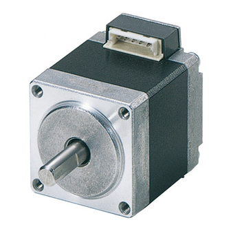
„ Overview of the product The CRK series is a motor and driver package product comprised of an open-case microstep driver equipped with smooth drive function and a five-phase stepping motor or various geared motors designed for high torque and low vibration. The smooth drive function allows microstep drive to be performed automatically within the driver without having to change the pulse setting, thereby enabling low vibration, low noise operation. - Page 3 *1 Approval conditions for UL 60950, UL 60950-1: Class III equipment, SELV circuit, Pollution degree 2 *2 Excluding CRD5128PB. *3 Oriental Motor declares compliance with the EMC Directives based on motor and driver combinations. z Low Voltage Directive This product is not subject to the EC’s Low Voltage Directive because its input power supply voltage is 24 VDC.
-
Page 4: Safety Precautions
Safety precautions The precautions described below are intended to prevent danger or injury to the user and other personnel through safe, correct use of the product. Use the product only after carefully reading and fully understanding these instructions. Handling the product without observing the instructions that accompany a “Warning”... - Page 5 Repair, disassembly and modification • Do not disassemble or modify the motor or driver. This may cause injury. Refer all such internal inspections and repairs to the branch or sales office from which you purchased the product. General • Do not use the motor and driver beyond their specifications. Doing so may result in injury or damage to equipment.
-
Page 6: Precautions For Use
Precautions for use This section covers limitations and requirements the user should consider when using the CRK series. z Conduct the insulation resistance measurement or withstand voltage test separately on the motor and the driver. Conducting the insulation resistance measurement or withstand voltage test with the motor and driver connected may result in injury or damage to equipment. - Page 7 z Rotating direction of the gear output shaft The relationship between the rotating direction of the motor shaft and that of the gear output shaft changes as follows, depending on the gear type and gear ratio. Rotating direction (Relative to the motor rotation direction) Gear type Gear ratio Motor size [mm (in.)]...
-
Page 8: Preparation
Preparation This section covers the points to be checked along with the names and functions of the respective parts. Checking the product Verify that the items listed below are included. Report any missing or damaged items to the branch or sales office from which you purchased the product. - Page 9 Combinations of motors and drivers • indicates A (single shaft) or B (double shaft). • „ represents a number indicating the gear ratio. „ High-resolution type Model Motor model Driver model CRK523PMP CRD5103P PK523PM CRK523PMPB CRD5103PB CRK523HPMP CRD5107HP PK523HPM CRK523HPMPB CRD5107HPB CRK524PMP...
- Page 10 „ High-torque type Model Motor model Driver model CRK513PP CRD5103P PK513P CRK513PPB CRD5103PB CRK523PP CRD5103P PK523P CRK523PPB CRD5103PB CRK523HPP CRD5107HP PK523HP CRK523HPPB CRD5107HPB CRK525PP CRD5103P PK525P CRK525PPB CRD5103PB CRK525HPP CRD5107HP PK525HP CRK525HPPB CRD5107HPB CRK544PP CRD5107P PK544P CRK544PPB CRD5107PB CRK546PP CRD5107P PK546P...
- Page 11 „ TH geared type Model Motor model Driver model CRK523PP-T„ CRD5103P PK523P-T„ CRK523PPB-T„ CRD5103PB CRK543P-T„ CRD5107P PK543W-T„ CRK543PB-T„ CRD5107PB CRK564P-T„ CRD5114P PK564W-T„ CRK564PB-T„ CRD5114PB „ PL geared type Model Motor model Driver model CRK543P-P„ CRD5107P PK543W-P„ CRK543PB-P„ CRD5107PB CRK545P-P„ CRD5107P PK545W-P„...
- Page 12 „ PN geared type Model Motor model Driver model CRK523PP-N„ CRD5103P PK523P-N„ CRK523PPB-N„ CRD5103PB CRK544P-N„ CRD5107P PK544W-N„ CRK544PB-N„ CRD5107PB CRK564P-N„ CRD5114P PK564W-N„ CRK564PB-N„ CRD5114PB CRK566P-N„ CRD5114P PK566W-N„ CRK566PB-N„ CRD5114PB „ Harmonic geared type Model Motor model Driver model CRK513PP-H„ CRD5103P PK513P-H„S CRK513PPB-H„...
- Page 13 Names and functions of parts This section covers the names and functions of parts in the motor and driver. See the reference page indicated for details on each part. „ Motor Illustration shows the PK56 type. Pilot Mounting holes (4 locations) Output shaft Motor leads (5 wires: blue, red, orange,...
- Page 14 z CRD5128PB MOSFET arrays Mounting cutout (2 locations) Mounting holes (2 locations) Name Description Power supply connector (CN1) Connect to a 24 VDC power supply. [p.26] I/O signals connector (CN2) Connect to I/O signals. [p.26] Motor connector (CN3) [p.26] Connect to motor leads. Set the operating current of the motor.
-
Page 15: Installation
Installation This chapter explains the installation location and installation methods of the motor and driver, as well as how to install a load. Location for installation The motor and driver are designed and manufactured for installation in equipment. Install them in a well-ventilated location that provides easy access for inspection. The location must also satisfy the following conditions: •... - Page 16 Installation method A Installation method B Mounting hole Metal plate Metal plate Mounting hole Pilot holder Bolt size, tightening torque and installation method Tightening Effective depth Frame size Installation Motor type Bolt size torque of bolt [mm (in.)] method [N·m (oz-in)] [mm (in.)] 20 (0.79) 0.25 (35)
- Page 17 z Using a coupling Align the centers of the motor’s output shaft and load shaft in a straight line. z Using a belt drive Align the motor’s output shaft and load shaft in parallel with each other, and position both pulleys so that the line connecting their centers is at a right angle to the shafts.
- Page 18 Permissible radial load and permissible axial load The radial load and the axial load on the motor’s output shaft must be kept under the permissible values listed on below. The figures in parenthesis { } are the values for the High-resolution or High-torque type motors.
- Page 19 Permissible radial load [N (lb.)] Distance from the tip of Permissible Gear Motor type Model motor’s output shaft [mm (in.)] axial load ratio [N (lb.)] (0.20) (0.39) (0.59) (0.79) (45) (49) (56) (63) (72) CRK566 PL geared 7.2, 10 100 (22) (56) (60) (67)
- Page 20 Permissible radial load [N (lb.)] Distance from the tip of Permissible Gear Motor type Model motor’s output shaft [mm (in.)] axial load ratio [N (lb.)] (0.20) (0.39) (0.59) (0.79) 5, 7.2, CRK523 − 40 (9) (10.1) (13.5) (18) (22) − (18) (21) (27)
- Page 21 „ Permissible moment load of the harmonic geared type When installing an arm or table on the flange surface, calculate the moment load using the formula below if the flange surface receives any eccentric load. The moment load should not exceed the permissible value specified in the table. Moment load: M [N·m (oz-in)] = F ×...
- Page 22 There must be a clearance of at least 25 mm (0.98 in.) and 50 mm (1.97 in.) in the horizontal and vertical directions, respectively, between the driver and enclosure or other equipment. When two or more drivers are to be installed side by side, provide 20 mm (0.79 in.) and 50 mm (1.97 in.) clearances in the horizontal and vertical directions, respectively.
- Page 23 Vertical installation Metal plate Spring washer M3 screw Metal plate M3 screw Spring washer * For CRD5128, affix with screws (two locations). • Review the operating conditions if the surface temperature of the mounting plate exceeds 75 °C (167 °F). •...
-
Page 24: Connection
Connection This chapter explains the connection methods, connection examples, and I/O signals about the driver and motor, power supply, and controller. Also, it explains the protection against noise and the compliance with the EMC Directive. A connector-coupled type motor is adopted for the high-resolution type, high-torque type and geared types (CRK513P, CRK523P).Use the supplied connector leads. - Page 25 „ PNP type Driver 24 VDC±10% Lead color Blue Orange Connector terminal number Green Black Controller V0 (+5 to 24 VDC) 220 Ω PLS (CW) 220 Ω DIR. (CCW) 220 Ω A.W.OFF 220 Ω 220 Ω C.D.INH V0 (+5 to 24 VDC) TIMING •...
- Page 26 „ Connector pin assignments for driver Connector No. Pin No. Type Signal Description Input +24 VDC POWER Input − Input PLS (CW) Pulse input (CW pulse) *1 Input − Input Rotation direction input DIR. (CCW) (CCW pulse) *1 Input − Input A.W.OFF All windings off input...
- Page 27 Applicable contacts and connector housings Connect the driver, using the following suitable contacts and connector housings. When crimping contacts for connectors, be sure to use the crimping tool specified by the connector maker. Accessories motor cables and driver cable sets (sold separately) are also available. See p.49 for details.
- Page 28 „ Connector housing, contact and crimping tool for motor • Manufacturer: For PK56PM J.S.T. Mfg. Co., Ltd. For other than PK56PM Molex Incorporated PK513P PK54P Motor type PK52P, PK52HP PK56PM PK54PM PK52PM, PK52HPM Connector housings 51065-0500 51103-0500 VHR-5N Contacts 50212-8100 50351-8100 BVH-21T-P1.1 AWG22, 20: YC-160R...
- Page 29 Explanation of I/O signals „ Input signals The signal states indicate the state of the internal photocoupler (ON: power conducted; OFF: power not conducted). • Example of connection with a • Example of connection with a current sink output circuit current source output circuit PLS, DIR., A.W.OFF PLS, DIR., A.W.OFF...
- Page 30 2-pulse input mode The controller’s CW pulses are connected to the CW+ (pin No.1) and the CW− (pin No.2), while the CCW pulses are connected to the CCW+ (pin No.3) and the CCW− (pin No.4). • When the CW pulse input changes from the ON state to OFF state, the motor will rotate one step in the CW direction.
- Page 31 z C/S (step angle switching) input This signal selects the step angle set with one of the two step angle setting switches (DATA1 and DATA2). For example, when DATA1 is set to [0: 0.72°] and DATA2 is set to [6: 0.072°], this signal can switch between 0.72°/step operation and 0.072°/step operation.
- Page 32 z TIMING (excitation timing) output When the motor excitation state (combined phases of current flowing) is the excitation home position (step 0), the driver switches on the timing output. The motor excitation state is reset to the excitation home position when the power supply is switched on. When the motor has a base step angle of 0.72°/step, the TIMING output turns ON with a rotation of every 7.2°...
- Page 33 Timing chart Motor operation 5 s or more Power supply input 0.5 s or more 10 µs or more 10 µs or more 300 µs or more PLS input 1 pulse input mode DIR. input CW input 2 pulse 10 µs or more input mode CCW input A.W.OFF input...
- Page 34 Noise measures The electrical noise is of two types: One is a noise to invade into the driver from the outside and cause the driver malfunction, and the other is a noise to emit from the driver and cause peripheral equipments malfunction. For the noise that is invaded from the outside, take measures to prevent the driver malfunction.
- Page 35 This cable is a shielded twisted pair cable for good noise immunity to connect the driver and controller. The ground wires useful to grounding are provided at both ends of the cable. The EMC measures are conducted using the Oriental Motor driver cable. z Pulse signal converter for noise immunity This is a noise filter for pulse signal lines.
- Page 36 Connecting the noise filter Refer to p.35 for details. z Power supply The CRK Series is a product of DC power input. Use a DC power supply (switched-mode power supply etc.) that conforms to the EMC Directive. z Connecting the signal Refer to “Prevention of noise propagation”...
- Page 37 z Precautions about static electricity Static electricity may cause the driver to malfunction or suffer damage. While the driver is receiving power, handle the driver with care and do not come near or touch the driver. Always use an insulated screwdriver to adjust the driver’s potentiometers. The driver uses parts that are sensitive to electrostatic charge.
-
Page 38: Setting
Setting Step angle When setting the motor’s step angle, use the resolution select switch and the step angle setting switches [DATA1] [DATA2]. Resolution select switch Step angle setting switches Factory setting R1 Factory setting DATA1: 0 DATA2: 0 DATA2 Resolution select switch (R1/R2) DATA1 For motors of the base step angle 0.72°, the step angles can be set are shown in the table... - Page 39 • Set to [R1] side when setting to the step angle in the “R1” side of the table. • Set to [R2] side when setting to the step angle in the “R2” side of the table. • Step angles are theoretical values. •...
- Page 40 Pulse input modes Either the 1-pulse or 2-pulse input mode may be Pulse input mode select switch (1P/2P) selected in accordance with the controller used. • When the motor is to be controlled through the pulse signal and the rotation direction signal that specifies the motor’s direction of rotation, set the to “1P”.
- Page 41 Motor current When the load is light and there is a margin for motor torque, the motor’s operating vibration and the temperature increase of the motor and driver can be held down by lowering the motor’s operating current and standstill current. Factory setting RUN: Motor rated current STOP: About 50% of motor’s rated current „...
- Page 42 4. Turn the motor operating current potentiometer (RUN) with a precision screwdriver, set the motor operating current. When the potentiometer is turned counterclock wise, the current decreases. The scale values are not displayed on the control. CRD5103PB, CRD5103P CRD5107PB, CRD5107HPB (Representative values) CRD5107P, CRD5107HP (Representative values)
- Page 43 5. Turn the C.D.INH input to OFF. 6. Continue setting the current while the motor is at a standstill. „ Setting current at motor standstill The current at motor standstill is factory set so that it will be about 50% of the motor’s operating current (This proportion does not change, even if the motor’s operating current is changed).
- Page 44 CRD5114PB, CRD5114P CRD5128PB (Representative values) (Representative values) 1.4 A/phase (factory setting) 0.7 A/phase (factory setting) STOP potentiometer STOP potentiometer 3. When the setting is complete, turn off the power supply. After about 0.1 sec. has passed since the pulse was stopped, the motor’s operating current automatically decreases to the set value of current at motor standstill.
-
Page 45: Inspection
Inspection It is recommended that periodic inspections be conducted for the items listed below after each operation of the motor. If an abnormal condition is noted, stop the use and contact your nearest office. Inspection items • Are the motor installation screws loose? •... -
Page 46: Troubleshooting And Remedial Actions
Troubleshooting and remedial actions During motor operation, the motor or driver may fail to function properly due to an improper speed setting or wiring. When the motor cannot be operated correctly, refer to the contents provided in this section and take appropriate action. If the problem persists, contact your nearest office. - Page 47 Phenomenon Possible cause Remedial action The centers of the motor’s Check the connection condition of output shaft and load shaft are the motor output shaft and load not aligned. shaft. Check for large load fluctuations during motor operation. If adjusting The load or load fluctuation is the operating pulse speed to low too high.
- Page 48 Phenomenon Possible cause Remedial action The centers of the motor’s Check the connection condition of output shaft and load shaft are the motor output shaft and load not aligned. shaft. If the vibration decreases when the operating pulse speed is changed, it means the motor is resonating.
-
Page 49: Accessories (Sold Separately)
Accessories (sold separately) „ Connection cable (for motor) The lead wires come preassembled with a crimped connector for easy connection of a connector-type motor. [A 0.6 m (2 ft.) connector leads come with the motor and driver package product.] Model Length Conductor Applicable product... - Page 50 „ Motor connector set A set of connector housings and contacts matching a connector-type motor. Each bag contains enough housings and contacts for connecting 30 motors. Applicable Connector Model Contacts Applicable cable motor housings PK513P PK523P PK525P PK523HP PK525HP AWG30 to 24 *1 PK523PM PK524PM (0.05 to 0.2 mm...
- Page 51 „ Connection cable (for signal) This is a shielded twisted pair cable for the driver control I/O (12 pins) that has good noise immunity. The ground wires useful to grounding are provided at both ends of the cable. Model Length [m (ft)] Conductor CC12D005-2 0.5 (1.6)
- Page 52 If a new copy is required to replace an original manual that has been damaged or lost, please contact your nearest Oriental Motor sales office. • Oriental Motor shall not be liable whatsoever for any problems relating to industrial property rights arising from use of any information, circuit, equipment or device provided or referenced in this manual.
Need help?
Do you have a question about the CRK Series and is the answer not in the manual?
Questions and answers