Advertisement
Quick Links
O P E R A T I N G M A N U A L
For 5-phase Stepping Motors
CVD driver SC type
Introduction .................................................1
Safety precautions ......................................1
Precautions for use ......................................2
Preparation ...................................................2
Installation ....................................................3
Connection ...................................................5
Setting ...........................................................9
Introduction
„ Before use
Only qualified personnel of electrical and mechanical engineering should
work with the product.
Use the product correctly after thoroughly reading the "Safety precautions"
In addition, be sure to observe the contents described in warning, caution,
and note in this manual.
The product described in this manual has been designed and manufactured
to be incorporated in general industrial equipment. Do not use for any other
purpose. Oriental Motor Co., Ltd. is not responsible for any damage caused
through failure to observe this warning.
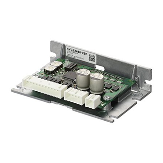
„ Overview of the product
This product is a driver for 5-phase stepping motors. Simply inputting
operation signals from a programmable controller can easily drive the motor
without using a pulse generator.
You can set two different operating speeds of high speed and low speed, and
also switch the speed by the input signal even while operating.
The CVD driver SC type defines the operating speed of the high speed side
as "Speed1" and the operating speed of the low speed side as "Speed2."
Programmable
controller
Safety precautions
The precautions described below are intended to prevent danger or injury
to the user and other personnel through safe, correct use of the product.
Use the product only after carefully reading and fully understanding these
instructions.
Description of signs
Handling the product without observing the instructions
that accompany a "Warning" symbol may result in serious
injury or death.
Handling the product without observing the instructions
that accompany a "Caution" symbol may result in injury
or property damage.
The items under this heading contain important handling
instructions that the user should observe to ensure safe
use of the product.
HM-60346-2
MSIP-REM-OMC-102
Alarm............................................................10
Maintenance/inspection ..........................11
General specifications ..............................11
Regulations and standards ......................11
Accessories..................................................11
Specifications .............................................13
Operating speed Setting value list .........14
Power
Driver
supply
Motor
Thank you for purchasing an Oriental Motor product.
This Manual describes product handling procedures and safety precautions.
y Please read it thoroughly to ensure safe operation.
y Always keep the manual where it is readily available.
Description of graphic symbols
Indicates "prohibited" actions that must not be performed.
Indicates "compulsory" actions that must be performed.
y Do not use the product in explosive or corrosive environments, in the
presence of flammable gases, locations subjected to splashing water,
or near combustibles. This may cause fire or injury.
y Do not forcibly bend, pull or pinch the cable. This may cause fire.
y Do not turn the AWO input to ON while the motor is operating. This
may cause injury or damage to equipment.
y Do not disassemble or modify the product. This may cause injury.
y Assign qualified personnel to the task of installing, wiring, operating/
controlling, inspecting and troubleshooting the product. Failure to
do so my result in fire or injury.
y If this product is used in a vertical application, be sure to provide a
measure for the position retention of moving parts. Failure to do so
may result in injury or damage to equipment.
y When the driver generates an alarm (any of the driver's protective
functions is triggered), first remove the cause and then clear the
alarm (protective function). Continuing the operation without
removing the cause of the problem may cause malfunction of the
driver, leading to injury or damage to equipment.
y Install the product in an enclosure. Failure to do so may result in
injury.
y Keep the driver's input-power voltage within the specified range.
Failure to do so may result in fire.
y For the driver power supply use a DC power supply with reinforced
insulation on its primary and secondary sides. Failure to do so may
result in electric shock.
y Connect the cables securely according to the wiring diagram. Failure
to do so may result in fire.
y Turn off the driver power in the event of a power failure. Failure to do
so may result in injury or damage to equipment.
y Do not use the product beyond its specifications. This may cause
injury or damage to equipment.
y Keep your fingers and objects out of the openings in the product.
Failure to do so may result in fire or injury.
y Do not touch the product while operating or immediately after
stopping. This may cause a skin burn(s).
y Do not forcibly bend or pull the cable that was connected to the
driver. Doing so may cause damage.
y Keep the area around the product free of combustible materials.
Failure to do so may result in fire or a skin burn(s).
y Leave nothing around the product that would obstruct ventilation.
Failure to do so may result in damage to equipment.
1
Advertisement

Related Manuals for Oriental motor CVD512B*-KSC series


Summary of Contents for Oriental motor CVD512B*-KSC series
-
Page 1: Table Of Contents
HM-60346-2 O P E R A T I N G M A N U A L Thank you for purchasing an Oriental Motor product. This Manual describes product handling procedures and safety precautions. For 5-phase Stepping Motors y Please read it thoroughly to ensure safe operation. CVD driver SC type y Always keep the manual where it is readily available. - Page 2 „ Information about nameplate The figure shows an example. y Use a motor and driver only in the specified combination. Failure to do so may result in fire. Driver model y Provide an emergency stop device or emergency stop circuit external Serial number to the equipment so that the entire equipment will operate safely Manufacturing date...
- Page 3 z Details of switches „ Installation direction Refer to p.9 for the setting method. The figure shows the factory setting. Install the driver on a metal plate having excellent vibration resistance in vertically or horizontally. If the driver is installed under conditions other than vertical or horizontal position, its heat radiation effect will deteriorate.
- Page 4 „ Dimension [unit: mm (in.)] „ Installation method The figure shows the driver which connector shape is of right angle. • When the connector shape is of standard y Install the driver using either of the "cutout for mounting A" or Mass: 0.06 kg (2.1 oz.) "cutout for mounting B."...
- Page 5 z CN3 (I/O signals) Connection Pin No. Direction Signal name Description For protection against electric shock, do not turn on the power supply until the wiring is Forward input − completed. Reverse input − „ Applicable connector Input All windings off input −...
- Page 6 „ Connecting the motor Connector pin assignments vary depending on the motor. Refer to the following table. The pin number is shown in the figure. “Color” in the table represents the color of the lead wire for the connection cable (supplied or sold accessory). The motors of the model A and model B are different in pin assignments.
- Page 7 z When using the voltage of input signals at 24 VDC Programmable controller Driver Current source output circuit Current sink output circuit 24 VDC 24 VDC Twisted pair cable 2.2 k 2.2 k 1.5 to 2.2 k , 0.5 W or more 2.2 k 2.2 k 1.5 to 2.2 k , 0.5 W or more...
- Page 8 „ Timing chart z Excitation timing Power supply input 0.2 s or less 10 s or less ALM output AWO input 0.1 s or less 0.2 s or less 0.2 s or less 0.2 s or less Excitation Motor excitation Non-excitation * Turn on the power supply again after the PWR/ALM LED is turned off.
- Page 9 Setting „ Conformity to the EMC Directive The figure shows the factory setting. Effective measures must be taken against the EMI that the motor and driver may give to adjacent control-system equipment, as well as the EMS of the motor and driver itself, in order to prevent a serious functional impediment in [Function setting switch] [Speed setting switch] the machinery.
- Page 10 z Operating current rate and standstill current rate „ Setting item • Operating current rate z Highest speed If the load is small and there is an ample allowance for torque, the motor The highest speed of the Speed1 is selected with the SPD H/L switch (function temperature rise can be suppressed by setting a lower operating current rate.
-
Page 11: General Specifications
Regulations and standards „ Alarm reset When the power is cycled, the alarm will be reset. Before resetting an alarm, always remove the cause of the alarm and ensure safety. „ CE Marking The overheat alarm can be reset by the AWO input if the circuit temperature of the driver goes down 75 °C (167 °F) and under. -
Page 12: Connection
„ CR circuit for surge suppression This product is effective to suppress the surge which occurs in a relay contact part. Use it to protect the contacts of the relay or switch. Model: EPCR1201-2 „ External resistor module Five current-limiting resistors, which are required when the 24 VDC output controller is connected to the driver, are mounted. -
Page 13: Specifications
Specifications y When the connector shape of the driver is of right angle, in the model names indicate R. y „ in the model names indicates A (single shaft) or B (double shaft) representing the motor type. • CVD512B-KSC Motor model PKP523N12„... -
Page 14: Operating Speed Setting Value List
Operating speed Setting value list Speed1: Selected one from 256 different speeds The actual operating speed is accurate within ±0.8% Pattern 1 against the set speed. Speed2: Fixed to a 10% speed of the Speed1 Speed1: Selected one from 16 different speeds Pattern 2 Speed2: Selected one from 16 different speeds in a range of 0.5 to 50% of the Speed1 „... - Page 15 „ Pattern 2...
- Page 16 February 2018 • Please contact your nearest Oriental Motor o ce for further information. Technical Support Tel:(800)468-3982 Singapore 8:30 to 5:00 , P.S.T. (M-F) Tel:1800-8420280 A.M. P.M. www.orientalmotor.com.sg 7:30 to 5:00 , C.S.T. (M-F) A.M. P.M. www.orientalmotor.com Tel:1800-806161 www.orientalmotor.com.my Tel:+55-11-3266-6018 www.orientalmotor.com.br...
Need help?
Do you have a question about the CVD512B*-KSC series and is the answer not in the manual?
Questions and answers