Table of Contents
Advertisement
Quick Links
Download this manual
See also:
User Manual
Advertisement
Table of Contents

Subscribe to Our Youtube Channel
Related Manuals for Dahua ITC237-PW1A-IRZ


Summary of Contents for Dahua ITC237-PW1A-IRZ
- Page 1 ITC237-PW1A-IRZ Installation Manual V 1.0...
-
Page 2: Device Structure
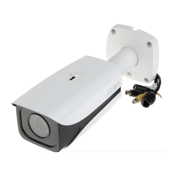
The camera is suitable for parking management systems, residential entrance management systems. 1.3 Device Structure 1.3.1 Appearance ITC237-PW1A-IRZ appearance is shown in Figure 1- 1 . Figure 1- 1 1.3.2 Dimensions ITC237-PW1A-IRZ dimensions are shown in Figure 1- 2. Unit is mm. - Page 3 Figure 1- 2 1.3.3 Technical Parameter and Port Wiring Parameter Parameter Name Value Type Model ITC237-PW1A-IRZ Sensor Type 1/1.9 inch CMOS Shutter 1/12.5~1/10000,manual or auto 0.002Lux/F1.2 Min Illumination (color),0.0002Lux/F1.2(B/W) Scan Method Progressive Day/Night IR-CUT Camera Full auto, customize range, Exposure Mode...
- Page 4 Parameter Parameter Name Value Type I/O Coil Trigger Support Trigger Mode Video Detection Support Max support 10000 white list White List vehicles, may directly link gateway output Plate recognition, plate color, vehicle Intelligent Recognition color, brand recognition Remote Control Remote config, control via WEB Function Support, may customize time, OSD Overlay...
- Page 5 Figure 1- 3 Port Note Port Function ① Audio Out Audio Output Port Output audio signal(N/A) Audio Input ② Audio In Input audio signal(N/A) Port ③ Network Port Connect to standard Ethernet ALARM_N Alarm Output Output alarm signal Port ALARM_C ALARM_IN Alarm Input Port ④...
-
Page 6: Device Installation
2 Device Installation 2.1 Installation Specifications 2.1.1 Standard Installation See Figure 2- 1 . Height 1.2 meters Snapshot line position Horizontal distance 4 meters Width ≤3.5 meters Figure 2- 1 Note: Camera monitoring the scene channel width requirements ≤3.5 m. > 3.5 m, requiring physical isolation parallel with the camera at 3.5 m spacing, make the passageway to meet the requirements of ≤3.5 m (Note: Refer to Fout! Verwijzingsbron niet... -
Page 7: Before Installation
Scene width adjustment, take a picture of the license plate from 100 to 140 pixels to identify the best effect. We recommend using a coil to snapshot program. 2.1.2 Before Installation Many factors affect the camera identification, such as channel width outside the camera monitoring capabilities, the camera installation point setting unreasonable. - Page 8 Left turn Right turn Yellow section vehicle’s continuous turning area, do not snapshot line here! Red line and below are finished turning area, Install camera at 4 plate is upright, you can meters behind draw snapshot line! snapshot line Exit Entrance Parking lot entrance/ exit...
- Page 9 Pedestrian Snapshot coil island Entrance channel Camera Channel is too wide, bracket make physical isolation Width≤3.5 meters Camera bracket and lane border <1.15 meter Figure 2- 3 2.2 Coil Cut 2.2.1 Coil Cut Specification Select coil snapshot scheme system, need to cut coil, see Figure 2- 4.
- Page 10 Figure 2- 4 Note: 1. Coil edge safety distance 30cm; 2. Coil edge depends on lane width; 3. Coil length (vehicle driving direction) 60cm; 4. Coil wind 4 times. 2.2.2 Coil Recommendation Loop coils are buried beneath the road surface, it is required that it should have good heat resistance, cold resistance, pull, anti-corrosion performance and flexibility.
- Page 11 2.3 AUX Installation Bracket ITC237-PW1A-IRZ model of camera, can be used for docking two stents, one for companies supporting pole bracket, the other is widely used in engineering all-direction bracket. According to user matching stand is different, their installations vary greatly, the...
- Page 12 2.3.1 Standard Bracket Installation Standard bracket and pedestal are shown in Figure 2- 6. Figure 2- 6 2.3.2 All-direction Bracket Matching Project common all-direction bracket has two models of WS2790 and 8081, both are identical interfaces. The following uses 8081 stand as an example, this project uses bracket installation method: Adopts all-direction joint to install, must used all-direction bracket, see Figure 2- 7 .
- Page 13 Figure 2- 7 The whole effect after installation. See Figure 2- 8 . Figure 2- 8 Bracket dimensions are shown in Figure 2- 9 . Camera Bracket Figure 2- 9...
-
Page 14: Wiring Reference
3 Common Application and Wiring Reference 3.1 Camera Common Application Figure 3- 1 Note: In above figure, dotted line is an optional device connected to device, the actual project have this device, determined according to the user program. In above figure, the two vehicle inspection device, the camera supports IO signal vehicle inspection device access;... - Page 15 Figure 3- 2 3.3 Camera Wiring Network Waterproof When you wire camera, you shall make sure network is water-proof, prevent crystal head copper aging. The accessories bag provides network water-proof joint, see Figure 3- 3 . Figure 3- 3...
-
Page 16: System Debugging
Note: ➢ Take out network waterproof head from random accessories bag; ➢ Insert network head in to waterproof joint; ➢ Make crystal head, test cable; ➢ Match cable, fasten waterproof joint. 4 System Debugging 4.1 Device Login Access camera via IE, on WEB you can browse and set camera real-time data and parameter, default IP address is 192.168.1.108. - Page 17 Right-click on Internet option of the IE browser's Properties or click on the IE page tool, open Internet Properties / Options window, select the Security tab, click Custom Level parameter button, see Figure 4- Figure 4- 1 The ActiveX controls and plug-related options are set to enable; Click Apply to complete the IE browser security level configuration.
- Page 18 4.1.4 WEB Page Intro IE after login camera, WEB page display, see Figure 4- 2, please refer WEB Operation Manual for page functions. Figure 4- 2 4.2 Scene Requirements See Figure 4- 3.
- Page 19 Figure 4- 3 Note: View of all channels on the right, leaving the left side of excess; Trigger lines (snapshot) in the image at 1/3; When adjust the camera angle, try to make sure the license plate level. 4.3 Camera General Parameter Note The camera in the parking lot entrances and exits the application, common (possibly modified) are snapshot, intelligent business, white list, camera attributes and Network...
- Page 20 one lane open. Advanced Configuration parameter event configuration, it can perform snapshot direction (the direction of the camera relative to the vehicle) the selection, provide forward, reverse two-way three directions, default bidirectional. See Figure 4- 4. Figure 4- 4 4.3.1.2 Snapshot Snapshot page, often uses OSD parameter.
- Page 21 4.3.1.3 Intelligent Business—Scene Intelligent Business parameter page, used scene configuration, recognition parameter. In scene configuration page, to be based on the use of environmental conditions paint lane recognition area. See Figure 4- 6. Figure 4- 6 To configure scene: Step 1. Click Video Analysis tab. Step 2.
- Page 22 Figure 4- 7 4.3.1.5 White List Some enterprises, toll-free parking, check user permissions on camera, under the authority to determine whether the applications of the gate opening, which use the camera a white list function. The camera's white list function involves white list and linkage gateway two parts, white list can be divided into white list settings and white list data, white list settings are some of the class argument white list data was white list database management parameters.
- Page 23 Figure 4- 9 4.3.1.6 Linkage Gateway Output See Figure 4- 10. Figure 4- 10 Note: Enable: Is option is enabled; Gateway Control: The camera offers three kinds of barrier of control options, you can also check the radio, where the white list gate with all vehicles are mutually exclusive. ...
-
Page 24: Image Parameter
4.3.2 Image Parameter Camera attribute parameter is image-related parameters, including shutter, gain, saturation, sharpness. The camera image parameters appropriately adjusted for differences in the actual application environment, and can enhance the camera image. See Figure 4- 11. Figure 4- 11 We recommended dual shutter, video shutter is 0 to 10, gain is 40;... -
Page 25: Web Upgrade
After IP is modified, you shall test network, ensure IP is modified correctly. Use PC ping command to test. 4.4 Device Program Upgrade Cameras WEB page has integrated update function; can use the Quick Configuration Tool (config tools) to upgrade two upgrade options. The following details the two upgrade. 4.4.1 WEB Upgrade Step 1. - Page 26 Step 3. Click Upgrade button. When device starts to upgrade, progress bat pops up, see Figure 4- 15. Figure 4- 15 After upgrading completes, device will auto reboot. See Figure 4- 16. Figure 4- 16 4.4.2 Config Tool Upgrade You can upgrade device via this Quick Configuration Tool either one by one or as a batch.
- Page 27 Figure 4- 17 Click on open. The open box pops up. Select upgrading file of the device and click on upgrade. You can see a prompt “system is transferring the file, please wait….” After transferring the file, system begins to upgrade. When upgrading is done, system pops up a dialogue box.
- Page 28 4.4.3 Restore Default Config Device upgrade two adjacent versions of the program, the controls basically compatible, not anything unusual after the upgrade. But before and after the upgrade version spans much of the program, such as upgrading from first base to third base (V2.1-V2.3), because the device capabilities expand, prone not compatible control and cause problems, such as WEB page display abnormal function key failure, some features cannot be achieved, etc., affect the actual use of the device.
-
Page 29: Before Upgrading
4.4.4 Before Upgrading If the device system upgrading fails, users find out the cause. If the device has upgrading file error, the user will replace the device upgrade file to the correct version and then upgrade the device. If the device is running, and other causes make the device unable to update the system, restart the quick configuration tool, log on fast configuration tool for device upgrade. - Page 30 Synchronize with the PC; Wrong time Device hardware failure, contact customer service. Dahua play is not installed, please download it from Dahua PC cannot play Dahua record file website. Play version is too low, update the player.
- Page 31 Note: This installation manual is for reference only. Slight difference may be found in user interface. All the designs and software here are subject to change without prior written notice. All trademarks and registered trademarks are the properties of their respective owners.
Need help?
Do you have a question about the ITC237-PW1A-IRZ and is the answer not in the manual?
Questions and answers