
Related Manuals for Zennio MINiBOX 20


Summary of Contents for Zennio MINiBOX 20
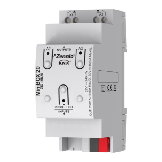
- Page 1 MINiBOX 20 2-Output Multifunction Actuator ZIO-MN20 Application programme version: [1.3] User manual edition: [1.3]_a www.zennio.com...
-
Page 2: Table Of Contents
MINiBOX 20 CONTENTS Contents ............................2 Document Updates ........................3 Introduction .......................... 4 1.1 MINiBOX 20 ........................4 1.2 Installation ........................5 1.3 Start-Up and Power Loss ....................6 Configuration......................... 7 2.1 General ..........................7 2.2 Outputs..........................9 2.2.1 Manual Control ......................9 2.3 Logic Functions ....................... -
Page 3: Document Updates
MINiBOX 20 DOCUMENT UPDATES Version Changes Page(s) Changes in the application program: Optimisation of the individual outputs, logic functions, [1.3]_a shutter channel y heartbeat modules. Minor text changes. http://www.zennio.com Technical Support: http://support.zennio.com... -
Page 4: Introduction
MINiBOX 20 1. INTRODUCTION 1.1 MINiBOX 20 MINiBOX 20 from Zennio is a versatile and small-size KNX actuator featuring a wide variety of functions and four relay outputs for a variety of applications, such as controlling shutter drives. The most outstanding features are: 2 relay outputs, configurable as: ... -
Page 5: Installation
MINiBOX 20 1.2 INSTALLATION MINiBOX 20 connects to the KNX bus through the on-board KNX connector. Once the device is provided with power from the KNX bus, both the individual address and the associated application programme may be downloaded. This device does not need any additional external power since it is entirely powered through the KNX bus. -
Page 6: Start-Up And Power Loss
MINiBOX 20 1.3 START-UP AND POWER LOSS During the start-up of the device, the Prog./Test LED will blink in blue colour for a few seconds before the device is ready. External orders will not be executed during this time, but afterwards. -
Page 7: Configuration
MINiBOX 20 2. CONFIGURATION 2.1 GENERAL After importing the corresponding database in ETS and adding the device into the topology of the desired project, the configuration process begins by entering the Parameters tab of the device. ETS PARAMETERISATION From the General parameter screen it is possible to activate/deactivate all the required functionality. - Page 8 MINiBOX 20 power failure). It is possible to parameterise a certain delay to this sending (0 to 255 seconds). Figure 3. Sending of Indication objects on bus voltage recovery Heartbeat (Periodical Alive Notification): incorporates a one-bit object to the project (“[Heartbeat] Object to Send ‘1’”) that will be sent periodically with a value of “1”...
-
Page 9: Outputs
Individual outputs. Shutters. 2.2.1 MANUAL CONTROL MINiBOX 20 allows manually switching the state of its output relays through the respective pushbuttons on the top of the device. A specific pushbutton is therefore available per output. Manual operation can be done in two different ways, named as Test On Mode (for testing purposes during the configuration of the device) and Test Off Mode (for a normal use, anytime). - Page 10 MINiBOX 20 mode. After that, an additional press will turn the LED yellow and then off, once the button is released. This way, the device leaves the Test On mode. Note that it will also leave this mode if a bus power failure takes place.
- Page 11 MINiBOX 20 Test On Mode After entering the Test On mode, it will only be possible to control the outputs through the on-board pushbuttons. Orders received through communication objects will be ignored, with independence of the channel or the output they are addressed to.
- Page 12 MINiBOX 20 ETS PARAMETERISATION The Manual Control is configured from the Configuration tab itself under Manual Control. The only two parameters are: Figure 5. Manual control screen Manual Control: options are “Disabled”, “Only Test Mode Off”, “Only Test Mode On” and “Test Mode Off + Test On Mode” (default). Depending on the selection, the device will permit using the manual control under the Test Off, the Test On, or both modes.
-
Page 13: Logic Functions
KNX bus, and to send the results through other communication objects specifically enabled for this purpose. MINiBOX 20 can implement up to 10 different and independent functions, each of them entirely customisable and consisting in up to 4 consecutive operations each. -
Page 14: Scene Temporisation
MINiBOX 20 2.4 SCENE TEMPORISATION The scene temporisation allows imposing delays over the scenes of the outputs. These delays are defined in parameters, and can be applied to the execution of one or more scenes that may have been configured. - Page 15 MINiBOX 20 Enabling a certain scene number n brings a new tab with such name to the menu on the left, from which it is possible to configure the temporisation of that scene for each of the outputs where it has been configured.
-
Page 16: Annex I. Communication Objects
MINiBOX 20 ANNEX I. COMMUNICATION OBJECTS “Functional range” shows the values that, with independence of any other values permitted by the bus according to the object size, may be of any use or have a particular meaning because of the specifications or restrictions from both the KNX standard or the application programme itself. - Page 17 MINiBOX 20 1 Bit C - - W - DPT_BinaryValue [Ox] On/Off N.O. (0=Open Relay; 1=Close Relay) 88, 96 N.C. (0=Close Relay; 1= Open 1 Bit C - - W - DPT_BinaryValue [Ox] On/Off Relay) 89, 97 1 Bit C T R - -...
- Page 18 Join and send us your inquiries about Zennio devices: http://support.zennio.com Zennio Avance y Tecnología S.L. C/ Río Jarama, 132. Nave P-8.11 45007 Toledo (Spain). Tel. +34 925 232 002 www.zennio.com info@zennio.com...
Need help?
Do you have a question about the MINiBOX 20 and is the answer not in the manual?
Questions and answers