
Related Manuals for Zennio MINiBOX 45v2


Summary of Contents for Zennio MINiBOX 45v2
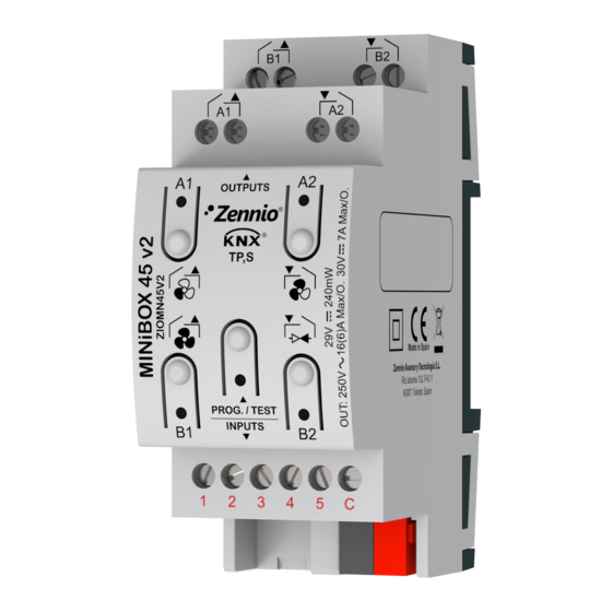
- Page 1 ➢ MINiBOX 45 v2 / MINiBOX 25 v2 Multifunction Actuator with 4 or 5 Outputs and 5 Inputs ZIOMN45V2 ZIOMN25V2 Application program version: [1.1] User manual edition: [1.1]_a www.zennio.com...
-
Page 2: Table Of Contents
Motion Detector ....................11 2.3 Outputs........................... 13 2.4 Logic Functions ....................... 14 2.5 Thermostats ........................15 2.6 Master Light ........................16 2.7 Scene Temporisation ...................... 19 2.8 Manual Control ......................21 ANNEX I. Communication Objects....................26 http://www.zennio.com Technical Support: http://support.zennio.com... - Page 3 MINiBOX 45 v2/MINiBOX 25 v2 DOCUMENT UPDATES Version Changes Page(s) Changes in the application program of MINiBOX 45 / 25 v2: [1.1_a] • Internal optimisation. http://www.zennio.com Technical Support: http://support.zennio.com...
-
Page 4: Introduction
1 INTRODUCTION 1.1 MINiBOX 25 v2 / MINiBOX 45 v2 MINiBOX 45 v2 and MINiBOX 25 v2 from Zennio are two versatile KNX actuators featuring a wide variety of functions, being both of them entirely equivalent except for the number of individual binary outputs available (four in MINiBOX 45 v2 and two in MINiBOX 25 v2) and by the incorporation of the functional block fancoil in the MINiBOX 45 v2. - Page 5 MINiBOX 45 v2/MINiBOX 25 v2 Manual operation / supervision of the 2 or 4 relay outputs through the on- board pushbuttons and LEDs. Heartbeat or periodical “still-alive” notification. Relay Switches Counter. http://www.zennio.com Technical Support: http://support.zennio.com...
-
Page 6: Installation
In such case, the LED will blink in red every 0.5 seconds. Outputs (7): output ports for the insertion of the stripped cables of the systems being controlled by the actuator (see section 2.3). Please secure the connection by means of the on-board screws. http://www.zennio.com Technical Support: http://support.zennio.com... -
Page 7: Start-Up And Power Loss
To get detailed information about the technical features of this device, as well as on the installation and security procedures, please refer to the corresponding Datasheet, bundled with the original package of the device and also available at www.zennio.com. 1.3 START-UP AND POWER LOSS During the start-up of the device, the Test/Prog. -
Page 8: Configuration
Logic Functions [disabled/enabled]: enables o disables the “Logic Functions” tab on the left menu. See section 2.4 for more details. The default values of each parameter will be highlighted in this document, as follows: [default/rest of options]. http://www.zennio.com Technical Support: http://support.zennio.com... - Page 9 (“[Heartbeat] Object to Send ‘1’”) that will be sent periodically with value “1” to notify that the device is still working (still alive). Figure 4. Heartbeat (Periodical Alive Notification). http://www.zennio.com Technical Support: http://support.zennio.com...
- Page 10 (“[Relay X] Number of Switches”) and the maximum number of switches carried out in a minute (“[Relay X] Maximum Switches per Minute”) http://www.zennio.com Technical Support: http://support.zennio.com...
-
Page 11: Inputs
X from Zennio) to the input ports of MINiBOX 45 / 25. Please refer to the specific user manual “Motion Detector”, available in the MINiBOX 45 / 25 v2 product section, at the Zennio website (www.zennio.com) for detailed information about the functionality and the configuration of the related parameters. - Page 12 MINiBOX 45 / 25 v2 (may report inaccurate measurements if connected to this device). When connected to MINiBOX 45 / 25 v2, the rear micro-switch of model ZN1IO- DETEC-P should be set to position “Type B”. http://www.zennio.com Technical Support: http://support.zennio.com...
-
Page 13: Outputs
For detailed information about the functionality and the configuration of the related parameters, please refer to the following specific manuals, all of them available in the MINiBOX 45 / 25 v2 product section at the Zennio website (www.zennio.com): Individual outputs. -
Page 14: Logic Functions
Please refer to the specific “Logic Functions” user manual (available in the MINiBOX 45 / 25 v2 product section at the Zennio homepage, www.zennio.com) for detailed information about the functionality and the configuration of the related parameters. -
Page 15: Thermostats
MINiBOX 45 v2/MINiBOX 25 v2 2.5 THERMOSTATS MINiBOX 45 v2 /MINiBOX 25 v2 implements four Zennio thermostats which can be enabled and configured independently. Please refer to the specific “Zennio Thermostat” user manual (available in the MINiBOX 45 / 25 v2 product section at the Zennio homepage, www.zennio.com) for detailed information about the functionality and the configuration of the related parameters. -
Page 16: Master Light
The Master Light function brings the option to monitor the state of up to 12 light sources (or even more, if the Master Light controls from multiple Zennio devices are linked together) or of any other elements whose state is transmitted through a binary object and, depending on those states, perform a master order every time a certain trigger signal (again, a binary value) is received through a specific object. - Page 17 The allowed range is 0 to 255 seconds. ➢ Binary Value [disabled/enabled]: if checked, object “[ML] General Switch- off: Binary Object” will be enabled, which will send one “0” whenever the general switch-off takes off. http://www.zennio.com Technical Support: http://support.zennio.com...
- Page 18 Note: object “[ML] Courtesy Switch-On: Binary Object” sends the value “1” (when the courtesy switch-on takes place), in contrast to object “[ML] General Switch-Off: Binary Object”, which sends the value “0” (during the general switch-off, as explained above). http://www.zennio.com Technical Support: http://support.zennio.com...
-
Page 19: Scene Temporisation
Enabling a certain Scene Number n [disabled/enabled] brings a new tab with such name to the menu on the left, from which it is possible to configure the temporisation of that scene for each of the outputs where it has been configured. http://www.zennio.com Technical Support: http://support.zennio.com... - Page 20 1 (the first in the scene configuration tab) and the lowest priority is the last. http://www.zennio.com Technical Support: http://support.zennio.com...
-
Page 21: Manual Control
Individual output: a simple press (short or long) will make the output switch http://www.zennio.com Technical Support: http://support.zennio.com... - Page 22 (on = relay closed; off = relay open). Note: the behaviour of the relays will depend on the parameterisation, i.e., on the number of fan speeds, and on the delay between switches. http://www.zennio.com Technical Support: http://support.zennio.com...
- Page 23 Test On mode until it matches the status objects. Fan Coil module: the behaviour is similar to that of the Test Off mode, although in this case the three fan speeds are supposed available. http://www.zennio.com Technical Support: http://support.zennio.com...
- Page 24 Test Off, the Test On, or both modes. Note that, as stated before, using the Test Off mode does not require any special action, while switching to the Test On mode does require long-pressing the Prog./Test button. http://www.zennio.com Technical Support: http://support.zennio.com...
- Page 25 ➢ Initialization [Unlocked / Locked / Last Value]: sets how the manual control should remain after the device start-up (after an ETS download or a bus power failure). “Last Value” (default; on the very first start-up, this will be Unlocked. http://www.zennio.com Technical Support: http://support.zennio.com...
-
Page 26: Annex I. Communication Objects
C - - W - DPT_Ack [Tx] Comfort Prolongation 0 = Nothing; 1 = Timed Comfort 1=Comfort 16, 54, 92, 130 1 Byte C T R - - DPT_HVACMode [Tx] Special Mode Status 1-Byte HVAC Mode 2=Standby http://www.zennio.com Technical Support: http://support.zennio.com... - Page 27 [Tx] [Sx] PI State (Heat) Greater than 0% 37, 43, 75, 81, 113, 119, 151, 157 0 = PI Signal 0%; 1 = PI Signal 1 Bit C T R - - DPT_Switch [Tx] [Sx] PI State Greater than 0% http://www.zennio.com Technical Support: http://support.zennio.com...
- Page 28 C T - - - DPT_Step [Ix] [Short Press] Stop/Step Down Shutter Sending of 1 (Stop/Step Down) Switching of 0/1 (Stop/Step 1 Bit C T - - - DPT_Step [Ix] [Short Press] Stop/Step Shutter (Switched) Up/Down) http://www.zennio.com Technical Support: http://support.zennio.com...
- Page 29 207, 213, 219, 225, 1 Bit C T - W - DPT_Switch [Ix] [Long Press] 0/1 Switching Switching 0/1 1 Bit C T - - - DPT_UpDown [Ix] [Long Press] Move Up Shutter Sending of 0 (Up) http://www.zennio.com Technical Support: http://support.zennio.com...
- Page 30 C T - - - DPT_Scaling 0% - 100% [Ix] [Long Press] Constant Value (Percentage) 0% - 100% 1 Byte C T - - - DPT_Value_1_Ucount 0 - 255 [Ix] [Long Press] Constant Value (Integer) 0 - 255 http://www.zennio.com Technical Support: http://support.zennio.com...
- Page 31 [Ix] External Motion Detection an external sensor 256, 261, 266, 285, 290, 295, 314, 319, 1 Byte C T R - - DPT_Scaling 0% - 100% [Ix] [Cx] Detection State (Scaling) 0-100% 324, 343, 348, 353, 372, 377, 382 http://www.zennio.com Technical Support: http://support.zennio.com...
- Page 32 487, 515 1 Byte C T R - - DPT_Scaling 0% - 100% [Cx] Shutter Position (Status) 0%=Top; 100%=Bottom 488, 516 1 Byte C - - W - DPT_Scaling 0% - 100% [Cx] Slats Positioning 0%=Open; 100%=Closed http://www.zennio.com Technical Support: http://support.zennio.com...
- Page 33 0 = Off; 1 = On 1 Bit C T R - - DPT_Switch [FCx] On/Off (Status) 0 = Off; 1 = On 1 Bit C - - W U DPT_Heat_Cool [FCx] Mode 0 = Cool; 1 = Heat http://www.zennio.com Technical Support: http://support.zennio.com...
- Page 34 [FCx] Heating Valve: Control Variable (1 bit) 0 = Open Valve; 1 = Close Valve 1 Bit C - - W U DPT_Switch [FCx] Heating Valve: Control Variable (1 bit) 0 = Close Valve; 1 = Open Valve http://www.zennio.com Technical Support: http://support.zennio.com...
- Page 35 4 Bytes C - - W - DPT_Value_4_Count [LF] (4-Byte) Data Entry x 4-Byte Data Entry 669, 670, 671, 672 2147483647 1 Bit C T R - - DPT_Bool [LF] Function x - Result (1-Bit) Boolean http://www.zennio.com Technical Support: http://support.zennio.com...
- Page 36 0 - 4294967295 [Relay x] Number of Switches Number of Switches 684, 686, 688, 690 2 Bytes C T R - - DPT_Value_2_Ucount 0 - 65535 [Relay x] Maximum Switches per Minute Maximum Switches per Minute http://www.zennio.com Technical Support: http://support.zennio.com...
- Page 37 Join and send us your inquiries about Zennio devices: http://support.zennio.com Zennio Avance y Tecnología S.L. C/ Río Jarama, 132. Nave P-8.11 45007 Toledo (Spain). Tel. +34 925 232 002. www.zennio.com info@zennio.com...
Need help?
Do you have a question about the MINiBOX 45v2 and is the answer not in the manual?
Questions and answers