
Subscribe to Our Youtube Channel
Related Manuals for Viega 6142.33


Summary of Contents for Viega 6142.33
- Page 1 Rotaplex Drain/Overflow Functional Unit Instructions for Use Model Year built: 6142.33 from 06/2015 en_INT...
- Page 2 Rotaplex Drain/Overflow Functional Unit 2 from 16...
-
Page 3: Table Of Contents
Table of contents Table of contents About these instructions for use Target groups Labelling of notes About this translated version Product information Intended use 2.1.1 Areas of use Product description 2.2.1 Overview 2.2.2 Technical data Accessories Handling Assembly information 3.1.1 Mounting conditions 3.1.2 Installation dimensions... -
Page 4: About These Instructions For Use
This restriction does not extend to possible operating instructions. The installation of Viega products must take place in accordance with the general rules of engineering and the Viega instructions for use. -
Page 5: About This Translated Version
About these instructions for use About this translated version This instruction for use contains important information about the choice of product or system, assembly and commissioning as well as intended use and, if required, maintenance measures. The information about the products, their properties and application technology are based on the current standards in Europe (e. -
Page 6: Product Information
The drain/overflow is suitable for extra long bathtubs. Detailed information regarding all bathtub models and the corre- sponding Viega drains / overflows can be found in the catalogue or on the Internet. An equipment set with rotatable rosette, valve cone and cover plate must be purchased separately. -
Page 7: Technical Data
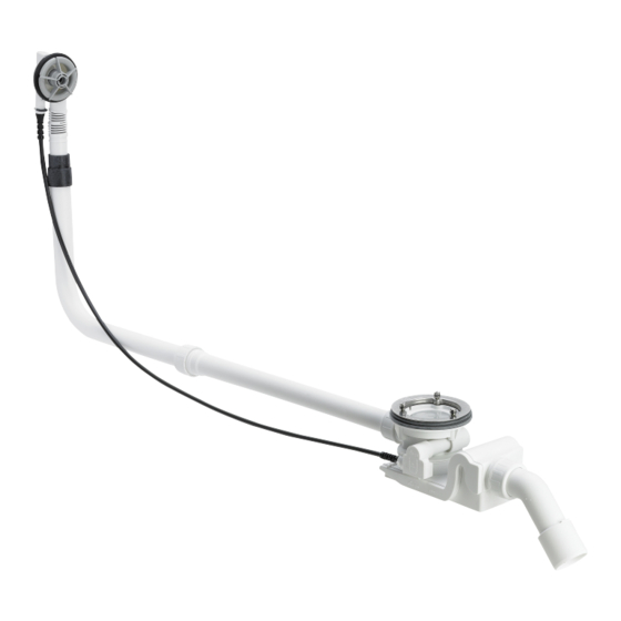
Product information 16 17 Fig. 1: Component overview fixing screws valve cone valve top double seal drain elbow union nut sliding ring seal odour trap 10 - pipe extension 11 - overflow pipe 12 - Bowden cable 13 - sleeve 14 - overflow unit 15 - profile seal 16 - O-ring... -
Page 8: Accessories
Product information DN (nominal diameter) drain sup- 40 / 50 mm port Length of Bowden cable 1070 mm Length 150–680 mm Height Dimensions and installation depth Ä Chapter 3.1.2 „Installation dimensions“ on page 10 Water head seal 50 mm Accessories The accessories shown here are not included in the scope of delivery. - Page 9 Product information Equipment set Rotaplex Visign R5: Model 6142.01 Optional accessories Rotaplex extension set It is possible to extend the odour trap below the bathtub in the case of bathtubs with a very thick floor. The extension set, model 6141.7, is available for such cases.
-
Page 10: Handling
Handling 3 Handling Assembly information 3.1.1 Mounting conditions The following requirements exist for the mounting of the drain / over- flow: The bathtub is installed. The drainage line is installed all the way to the bathtub. The underside of the bathtub is accessible. 3.1.2 Installation dimensions Fig. -
Page 11: Assembly
Handling Assembly 3.2.1 Mounting overflow Proceed as follows to the mounting of the overflow: Fit profile seal in the overflow unit. Push the rubber sleeve onto the overflow unit pipe until the lower edge is flush with the edge of the overflow pipe. Place the O-ring in the annular gap of the fixing flange. -
Page 12: Connecting Overflow And Drain
Handling Position the drain unit on the double seal from below in such a posi- tion that the upstand of the drain unit is placed in the recess of the double seal. Fit the valve top in the double seal. Place the fixing screws in the drain unit and pull hand tight. -
Page 13: Connecting The Wastewater System
Handling Mount union nut, sliding ring and seal. Screw together overflow and extension pipes. Maintain an insertion depth of at least 15 mm! Hold the pipe of the overflow unit parallel to the overflow pipe and mark the positions where the drain and the overflow should be con- nected. -
Page 14: Mounting Equipment Set
Handling Push union nut, sliding ring and seal onto the drain elbow. Screw the union nut on the drain unit. Align the odour trap in such a way that the drain elbow can be con- nected to the wastewater pipe. Turn the drain for this purpose. Push wastewater pipe in the drain elbow. -
Page 15: Leakage Test
Handling Place the cover plate onto the valve top and affix. The holes on the underside of the cover plate must be placed onto the heads of the screws. 3.2.6 Leakage test The leakage test is only carried out as a visual inspection. Check the points marked in the following drawing with particular care: Check drain fitting for visible leaks. -
Page 16: Maintenance
Handling Turn rotatable rosette to the right. ð The drain opens itself. INFO! The valve cone lifts and the water can flow away. The cover plate does not alter its position. Maintenance NOTICE! Risk of damage due to unsuitable cleaning agent. The following cleaning agents can damage chrome-plated surfaces and therefore may not be used: –...
Need help?
Do you have a question about the 6142.33 and is the answer not in the manual?
Questions and answers