
Related Manuals for Phytec phyBOARD Regor AM335x


Summary of Contents for Phytec phyBOARD Regor AM335x
- Page 1 ® phyBOARD -Regor AM335x Application Guide Document No.: L-823e_2 SBC Prod. No.: PB-01802-xxx CB PCB No.: 1447.3 SOM PCB No.: 1358.4 Edition: June 2018 A product of a PHYTEC Technology Holding company...
- Page 2 GmbH neither gives any guarantee nor accepts any liability whatsoever for consequential damages resulting from the use of this manual or its associated product. PHYTEC Messtechnik GmbH reserves the right to alter the information contained herein without prior notification and accepts no responsibility for any damages that might result.
-
Page 3: Table Of Contents
3.1 Expansion Connector (X6) ................25 3.1.1 C Connectivity ................27 Technical Specifications ................28 4.1 Product Power Rating ................... 29 4.2 Product Temperature Grades ................29 Revision History ..................31 Index ......................32 PHYTEC Messtechnik GmbH 2018 L-823e_2... - Page 4 Figure 14: Digital GPIOs at Connector X2 ..............20 Figure 15: Card Edge Connector X7 ................22 Figure 16: Boot Switch S4 ..................23 Figure 17: System Reset Button S2 ................23 Figure 18: Expansion Connector X6 ................25 PHYTEC Messtechnik GmbH 2018 L-823e_2...
-
Page 5: List Of Tables
Pin Assignment of CardEdge Connector X7............22 Table 14: Boot Switch Configuration for S4..............23 Table 15: Pin Assignment of PHYTEC Expansion Connector X6 ........... 25 Table 16: C Addresses in Use ................... 27 Table 17: Power ratings of the phyBOARD-Regor ............29 Table 18: Product Temperature Grades ................ -
Page 6: Conventions, Abbreviations And Acronyms
Tables which describe jumper settings show the default position in bold, blue text. blue italic Text in indicates a hyperlink within, or external to the document. Click these links to quickly jump to the applicable URL, part, chapter, table, or figure. PHYTEC Messtechnik GmbH 2018 L-823e_2... -
Page 7: Table 1: Abbreviations And Acronyms Used In This Manual
Solderless jumper; these types of jumpers can be removed and placed by hand with no special tools Not Connected Not Mounted Not Specified Printed circuit board PHYTEC Display Interface; defined to connect PHYTEC display adapter boards or custom adapters PHYTEC Expansion Board PMIC Power management IC Power over Ethernet... - Page 8 Beginning with BSP version AM335x-PD14.1-rc1, it is possible to configure the BSP in regards to the hardware configuration. This allows the user to easily adapt the BSP if an expansion board is attached, removed or exchanged. PHYTEC Messtechnik GmbH 2018 L-823e_2...
-
Page 9: Preface
® As a member of PHYTEC's new phyBOARD product family, the phyBOARD-Regor AM335x is one of a series of PHYTEC System on Modules (SBCs) that offer off-the-shelf solutions for a ® huge variety of industrial applications. The new phyBOARD product family consists of a series of extremely compact embedded control engines featuring various processing performance classes. - Page 10 Software Support Production-ready Board Support Packages (BSPs) and Design Services for our hardware will further reduce development time and risk, while at the same time allowing for increased focus on the product expertise. viii PHYTEC Messtechnik GmbH 2018 L-823e_2...
- Page 11 OEM modules, which can be embedded directly into the user’s peripheral hardware design. Take advantage of PHYTEC products to shorten time-to-market, reduce development costs, and avoid substantial design issues and risks. With this new innovative full system solution, new ideas can be brought to market in the most timely and cost-efficient manner.
- Page 12 3m. PHYTEC products fulfill the norms of the European Union’s Directive for Electro Magnetic Conformity only in accordance with the descriptions and rules of usage indicated in this hardware manual (particularly in respect to the pin header row connectors, power connector and serial interface to a host-PC).
- Page 13 Product Change Management and information in this manual on parts populated on the SOM / SBC With the purchace of a PHYTEC SOM / SBC, you will, in addition to our HW and SW offerings, receive free obsolescence maintenance service for the HW we provide.
- Page 14 AM335x [PB-01802-xxx] PHYTEC Messtechnik GmbH 2018 L-823e_2...
-
Page 15: Introduction
1.1.1 Features of the phyBOARD-Regor AM335x The phyBOARD-Regor AM335x supports the following features : • Developed in accordance with PHYTEC's new SBCplus concept ( Preface • PHYTEC’s phyCORE-AM335x SOM • Phoenix Contact ME Max 3U1 standard dimensions •... -
Page 16: Block Diagram
AM335x [PB-01802-xxx] 1.1.2 Block Diagram Figure 1: Block Diagram of the phyBOARD-Regor AM335x PHYTEC Messtechnik GmbH 2018 L-823e_2... -
Page 17: View Of The Phyboard-Regor Am335X
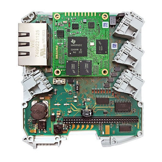
Introduction 1.1.3 View of the phyBOARD-Regor AM335x Figure 2: View of the phyBOARD-Regor AM335x with phyCORE-AM335x Figure 3: phyBOARD-Regor AM335x connectors PHYTEC Messtechnik GmbH 2018 L-823e_2... -
Page 18: Accessing The Phyboard-Regor Features
AM335x [PB-01802-xxx] Accessing the phyBOARD-Regor Features PHYTEC phyBOARD-Regor is fully equipped with all mechanical and electrical components necessary for a speedy and secure start-up. Overview of the phyBOARD-Regor Peripherals Figure 2 The phyBOARD-Regor is depicted in . It features many different interfaces and is... - Page 19 User's Manual/Data Sheets. As damage from improper connections can vary according to use and application, it is the user‘s responsibility to take appropriate safety measures to ensure that the module connections are protected from overloading through connected peripherals. PHYTEC Messtechnik GmbH 2018 L-823e_2...
-
Page 20: Leds
USB Micro-AB connector X4 green 5 V voltage generation of the phyBOARD-Regor 2.2.1.2 3.3 V voltage of the phyBOARD-Regor (approved and green enabled by supply voltage supervisor IC) Table 3: phyBOARD-Regor LEDs Descriptions PHYTEC Messtechnik GmbH 2018 L-823e_2... -
Page 21: Table 3: Phyboard-Regor Leds Descritption (Continued)
3.3 V voltage on the output of the LDO (has to be 2.2.1.2 green approved and enabled by supply voltage supervisor IC to supply the phyBOARD-Regor) green RUN/STOP status LED 2.2.1.3 ERROR status LED Table 3: phyBOARD-Regor LEDs Descritption (continued) PHYTEC Messtechnik GmbH 2018 L-823e_2... -
Page 22: Switches
Figure 5 Table 4 shows the location of the switches. Their functions are listed in Switch Description Section 2.2.10 Reset Button 2.2.9 Boot Switch Table 4: phyBOARD-Regor Switches Description PHYTEC Messtechnik GmbH 2018 L-823e_2... -
Page 23: Jumpers
By default, JP3 is set to terminate the CAN interface. J5 and J6 are set to connect the RS485 interface to the card edge connector X7. Due to the small footprint of the solder jumpers (J), PHYTEC does not recommend manual jumper modifications. This might also render the warranty invalid. -
Page 24: Functional Components On The Phyboard-Regor Sbc
COMBICON base strip X1 or, alternatively, at the CARD Edge connector X7 ( ). A 24 V adapter with a minimum supply of 1A is recommended to supply the board. A 3A socketed SMD Littelfuse 452 (F1) is used to protect the phyBOARD-Regor against over-current. PHYTEC Messtechnik GmbH 2018 L-823e_2... -
Page 25: Power Leds D62, D63, And D68
IC and is interconnected to the phyBOARD-Regor to supply its components. The presence of the approved 3.3 V phyBOARD-Regor supply voltage is indicated by D63. Figure 4 shows the locations of the three LEDs. PHYTEC Messtechnik GmbH 2018 L-823e_2... -
Page 26: Status Leds D66 And D67
VBAT (A2) of the phyCORE-AM335x and supplies the module's RTC and some critical registers of the Power Management IC when the primary system power, X_VIN, is removed. The backup supply lasts approximately 7 days. PHYTEC Messtechnik GmbH 2018 L-823e_2... -
Page 27: Uart Connectivity (X3, X5, X6, X7)
X5 (1×5 positions Phoenix Contact MINI COMBICON 2.2.2.1 RS-232 connector 3.5 mm pitch) UART2 X6 (2×30 socket connector 2 mm pitch) UART3 X6 (2×30 socket connector 2 mm pitch) Table 7: Connectors and Signal Levels of the UART Interfaces PHYTEC Messtechnik GmbH 2018 L-823e_2... -
Page 28: Rs-232 Connectivity (X5)
UART2 serial receive signal RS-232 level (receive signal from UART2_RXD_RS232 peripheral device at phyBOARD-Regor) UART2 serial transmit signal RS-232 level (send signal to UART2_TXD_RS232 peripheral device from phyBOARD-Regor) Table 8: Pin Assignment of the RS-232 Interface at Connector X5 PHYTEC Messtechnik GmbH 2018 L-823e_2... -
Page 29: Rs-485 Connectivity (X3)
X_UART1_RS485_A UART1 serial A signal RS-485 level X_UART1_RS485_B UART1 serial B signal RS-485 level Ground X_CANH CAN High signal CAN1 X_CANL CAN Low signal CAN1 Table 9: Pin Assignment of the RS-485 Interface at Connector X3 PHYTEC Messtechnik GmbH 2018 L-823e_2... -
Page 30: Can Connectivity (X3, Jp3)
Depending on the muxing options, a second CAN interface (DCAN0 of the section 3.1 phyCORE-AM335x) is available on expansion port X6 ( ). DCAN0 (TX and RX) can be used instead of UART0 (RX and TX) or MMC2 (DAT1 and DAT2). PHYTEC Messtechnik GmbH 2018 L-823e_2... -
Page 31: Ethernet Connectivity (X9)
IP number to the hardware’s MAC address. In order to guarantee that the MAC address is unique, all addresses are managed in a central location. The MAC address of the phyBOARD-Regor is saved on the CPU (AM335x). PHYTEC Messtechnik GmbH 2018 L-823e_2... -
Page 32: Usb Connectivity (X4, X6)
USB1_VBUS at expansion connector X6. shows the location of the two LEDs. Due to the small footprint of the resistors, PHYTEC does not recommend manual jumper modifications. This might also render the warranty invalid. Contact the PHYTEC sales team if you need USB configurations different from the default configuration. -
Page 33: Secure Digital Memory Card/ Multimedia Card (X11)
DIP switch S4 allows the device to toggle between booting from NAND or SD card. In order section 2.1.3 to boot from an SD card, S4 must be switched ON (refer to for further information). PHYTEC Messtechnik GmbH 2018 L-823e_2... -
Page 34: Digital Gpios 1-4 (X2)
When the GPIOs on the phyBOARD-Regor are used as digital inputs, they are configured active high with the following switching voltages: Signal Level Voltage H-Level >11 V L-Level <5 V Table 11: Digital input switching levels for GPIO 1-4 PHYTEC Messtechnik GmbH 2018 L-823e_2... - Page 35 Digital Input/Output DIGIO3 (connects to GPIO0_23 (IN) and GPIO1_13 (OUT) of the AM335x) Digital Input/Output DIGIO4 (connects to GPIO0_22 (IN) and GPIO1_12 (OUT) of the AM335x) Ground Table 12: Pin Assignment of GPIO Connector X2 PHYTEC Messtechnik GmbH 2018 L-823e_2...
-
Page 36: Card Edge Connector (X7)
Figure 15: Card Edge Connector X7 The Card Edge Connector at X7 is a PHYTEC development connector and allows other custom expansion boards or DIN rail bus modules to be connected. The connector can be used as a section 2.1.4... -
Page 37: Boot Mode (S4)
X_nRESET_IN pin (X64A11) of the phyCORE SOM low, causing the module to reset. Additionally, the reset signal nRESET_OUT is generated on the module and will also reset the peripherals on the carrier board. PHYTEC Messtechnik GmbH 2018 L-823e_2... -
Page 38: Rtc
40 (X_INT_RTCn) at expansion connector X6 need to be shortcut ( The phyBOARD-Regor is equipped with a Gold Capacitor (C339 placed next to connector X6) section 2.2.1.4 which is also intended to back up the external RTC ( PHYTEC Messtechnik GmbH 2018 L-823e_2... -
Page 39: System Level Customizing
X_UART0_RXD 3.3 V interface) X_I2C0_SDA 3.3 V I2C0 Data UART 0 transmit data (standard debug X_UART0_TXD 3.3 V interface) X_I2C0_SCL 3.3 V I2C0 Clock Ground Table 15: Pin Assignment of PHYTEC Expansion Connector X6 PHYTEC Messtechnik GmbH 2018 L-823e_2... - Page 40 3.3 V AM335x non-maskable interrupt Table 15: Pin Assignment of PHYTEC Expansion Connector X6 (continued) These pins are configured as GPIO pins. To use them as MMC/SD card interface, the pin muxing must be changed and additional software development is required.
-
Page 41: C Connectivity
VCC5V_IN 5.0 V 5 V input supply voltage Table 15: Pin Assignment of PHYTEC Expansion Connector X6 (continued) If the SPI-NOR Flash on the phyCORE-AM335x is populated, the SPI signals on the expansion port cannot be used. 3.1.1 C Connectivity... -
Page 42: Technical Specifications
X1, X2, X3, X5: Manufacturer Phoenix Contact MC 1,5/ 5-ST-3,5 GY7035 - 1769087 Phytec article number: GP354 Please refer to the corresponding data sheets and mechanical specifications provided by www.phoenixcontact.com Phoenix Contact® ( PHYTEC Messtechnik GmbH 2018 L-823e_2... -
Page 43: Product Power Rating
PHYTEC offers SOMs in different configurations, making use of those temperature qualifications. To indicate which level of temperature qualification is used for active and passive parts of a SOM configuration, PHYTEC has categorized SOMs in Table 18 three temperature grades. -
Page 44: Table 18: Product Temperature Grades
-20 °C to +105 °C -40 °C to +95 °C -40 °C to +85 °C Consumer Consumer Commercial 0 °C to +95 °C 0 °C to +95 °C 0 °C to +70 °C Table 18: Product Temperature Grades PHYTEC Messtechnik GmbH 2018 L-823e_2... -
Page 45: Revision History
Changes in this manual 30.08.2016 Manual First edition. L-823e_1 Describes the phyBOARD-Regor AM335x SOM (PCB 1358.3) with phyBOARD-Regor- Carrier Board (PCB 1447.1). 27.06.2018 Manual Second edition. L-823e_2 Updated layout for the phyBOARD-Regor Carrier Board (PCB 1447.3). PHYTEC Messtechnik GmbH 2018 L-823e_2... -
Page 46: Index
D8 ..........18 X2 ............. 20 LINK LED ..........17 X3 ..........13, 16 X4 ............. 18 X5 ............. 13 MAC Address ........17 X6 ........... 13, 18, 25 X7 ..........13, 22 X9 ............. 17 PHYTEC Messtechnik GmbH 2018 L-823e_2... - Page 47 How would you improve this manual? Did you find any mistakes in this manual? page Submitted by: Customer number Name: Company: Address: Return to: PHYTEC Messtechnik GmbH Postfach 100403 D-55135 Mainz, Germany Fax : +49 (6131) 9221-33 PHYTEC Messtechnik GmbH 2017 L-823e_2...
- Page 48 AM335x [PB-01802-xxx] Published by PHYTEC Messtechnik GmbH 2018 Ordering No. L-823e_2 Printed in Germany...
Need help?
Do you have a question about the phyBOARD Regor AM335x and is the answer not in the manual?
Questions and answers