Table of Contents
Advertisement
Quick Links
3 t
ColorMax
Customer Product Manual
P/N 7135457_E
Issued 05/17
For parts and technical support, call your nearest Finishing Customer Support Centre.
Find your nearest centre at www.nordson.com/directory
This document is available on the Internet at http://emanuals.nordson.com/finishing
NORDSON GmbH ERKRATH GERMANY
Advertisement
Table of Contents
Troubleshooting

Related Manuals for Nordson ColorMax3


Summary of Contents for Nordson ColorMax3
- Page 1 Customer Product Manual P/N 7135457_E Issued 05/17 For parts and technical support, call your nearest Finishing Customer Support Centre. Find your nearest centre at www.nordson.com/directory This document is available on the Internet at http://emanuals.nordson.com/finishing NORDSON GmbH ERKRATH GERMANY...
- Page 2 40699 Erkrath, Germany Notice This is a Nordson Corporation publication which is protected by copyright. Original copyright date 2007. No part of this document may be photocopied, reproduced or translated to another language without the prior written consent of Nordson Corporation. The information contained in this publication is subject to change without notice.
- Page 3 Change Record Change Record Revision Date Change 18/05/2017 Pneumatic & Electrical diagrams updated Part 7135457- E E 2017 Nordson Corporation...
- Page 4 Change Record Part 7135457- E E 2017 Nordson Corporation...
-
Page 5: Table Of Contents
......Pneumatic & Electrical Diagrams ......Part 7135457- E E 2017 Nordson Corporation... - Page 6 46-40-932 882 Switzerland 41-61-411 3838 41-61-411 3818 Hot Melt 44-1844-26 4500 44-1844-21 5358 United Kingdom Industrial 44-161-498 1500 44-161-498 1501 Coating Systems Distributors in Eastern & Southern Europe DED, Germany 49-211-92050 49-211-254 658 E 2012 Nordson Corporation NI_EN_O-0211 All rights reserved...
- Page 7 Introduction Outside Europe / Hors d’Europe / Fuera de Europa For your nearest Nordson office outside Europe, contact the Nordson offices below for detailed information. Pour toutes informations sur représentations de Nordson dans votre pays, veuillez contacter l’un de bureaux ci-dessous.
-
Page 8: Safety
Intended Use Use of Nordson equipment in ways other than those described in the documentation supplied with the equipment may result in injury to persons or damage to property. -
Page 9: Regulations And Approvals
Regulations and Approvals Make sure all equipment is rated and approved for the environment in which it is used. Any approvals obtained for Nordson equipment will be voided if instructions for installation, operation, and service are not followed. All phases of equipment installation must comply with all federal, state, and local codes. -
Page 10: Grounding
Clean, maintain, test, and repair equipment according to the instructions in your equipment documentation. Use only replacement parts that are designed for use with original equipment. Contact your Nordson representative for parts information and advice. Grounding WARNING: Operating faulty electrostatic equipment is hazardous and can cause electrocution, fire, or explosion. -
Page 11: Action In The Event Of A Malfunction
Disconnect and lock out electrical power. Close pneumatic shutoff valves and relieve pressures. Identify the reason for the malfunction and correct it before restarting the equipment. Disposal Dispose of equipment and materials used in operation and servicing according to local codes. Part 7135457- E E 2017 Nordson Corporation... -
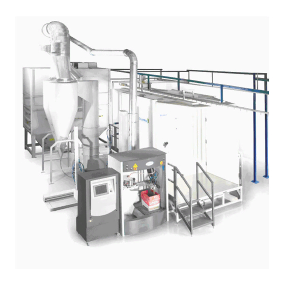
Page 12: Description
Description Section 2 Description Intended Use The Nordson ColorMax Booth System is designed primarily as fast and easy clean booth. Description of Components Figure 2 Typical ColorMax Booth System Part 7135457- E E 2017 Nordson Corporation... - Page 13 Description The Nordson ColorMax booth system forms part of a family of powder booths based on proven Nordson booth technology. The booth system offers an economical easy clean alternative to other due to the method of construction. The booth structure is made up of a combination of stainless steel platform, Apogee...
-
Page 14: Installation
NOTE: Booths are generally delivered flat pack for on- site assembly. NOTE: Installation of the booth should not be undertaken without the presence of a Nordson representative or a suitably qualified person. 1. Choose a level site on which to install the ColorMax Booth, away from drafts or any other airborne contaminates. -
Page 15: Electrical Connection
Pneumatic Connection WARNING: The air supply pressure should be set to 4 bar (maximum) and should only be modified by a Nordson technician. Connect the air supply to the booth pneumatic panel and ensure that the air supply is of the required quality. Also check that the air has been discharged from the system via the tank inlet filter to ensure that any material left in the line during installation does not enter the system. -
Page 16: Booth Conditioning Procedure
8. Spray powder to waste for 5 minutes, solvent clean any areas which preferentially collect powder. 9. Clean cyclone and recycle in the normal way. 10. The system is now ready for use. Part 7135457- E E 2017 Nordson Corporation... -
Page 17: Recommended Cleaning Solvent
Listed below is the composition of solvent we recommend for the initial set up and for maintenance cleaning. Distillate: 5% Butylacetate: 17% Cellesolve-Acetate: 5% Acetone: 20% Benzene 80/110: 15% Xylol: 38% The nearest standard solvent available to the above is cellulose thinners. Part 7135457- E E 2017 Nordson Corporation... -
Page 18: Operation
8. Start spraying powder and run production. Refer to Powder Feed Centre manuals. 9. After approx. 2 minutes of recycled powder being returned back through the recycle hose, move the hose into the sieve holster. Part 7135457- E E 2017 Nordson Corporation... -
Page 19: Color Change Procedure
8. Blow off the exterior of the dip legs and fluid assist. Refer to Powder Feed Centre manuals. 9. Start the pump purge sequence. Refer to Powder Feed Centre manuals. Figure 4-3 Spray guns in purge position Part 7135457- E E 2017 Nordson Corporation... - Page 20 15. If required, when most of the powder has been blown away wipe the inside of the booth with a damp cloth, ensure the cloth is damp only. Figure 4-5 Open duct door Part 7135457- E E 2017 Nordson Corporation...
- Page 21 23. Clean down the rest of the Powder Feed Centre. 24. Load new powder by putting the powder box on the vibrator table. Refer to Powder Feed Centre manual. Figure 4-7 ColorMax Powder Feed Centre ready for the new batch Part 7135457- E E 2017 Nordson Corporation...
-
Page 22: Maintenance
Every four hours or less check the feeder hopper or powder box for powder level. Every four hours check the powder pump and gun, clean according to the product manual. Part 7135457- E E 2017 Nordson Corporation... - Page 23 Maintenance Part 7135457- E E 2017 Nordson Corporation...
-
Page 24: Troubleshooting
The unit does not contain any user serviceable parts; approved parts available from Nordson must replace any parts that fail. Part 7135457- E E 2017 Nordson Corporation... -
Page 25: Table Of Troubleshooting
Discuss with supplier Low gun Kv or wrong setting See application manuals Cyclone loss Surge hopper seal faulty Replace seal Surge hopper over filling Check recycle system for blockages Inspection door seal leaking Replace seal Part 7135457- E E 2017 Nordson Corporation... -
Page 26: Parts
A dash (—) is used when the part number applies to all parts in the illustration. The number in the Part column is the Nordson Corporation part number. A series of dashes in this column (- - - - - -) means the part cannot be ordered separately. - Page 27 Kit,valve diaphram, purge tank (figure 2) NOTE A: Valve is fitted to the pulse tanks under the booth. check first which you have. NS: Not Shown AR: As Required 1. Figure 1 2. Figure 2 Part 7135457- E E 2017 Nordson Corporation...
-
Page 28: Pneumatic & Electrical Diagrams
Pneumatic & Electrical Diagrams Section 8 Pneumatic & Electrical Diagrams Description Part Number ColorMax3 Pneumatics & J- Box Booth Base 02- 258- 423 rev R Part 7135457- E E 2017 Nordson Corporation... - Page 37 Silflex-N Cable name Cable type Connection point Jumper Terminal Connection point Cable name Cable type...
- Page 38 -W12 Silflex-N Silflex-N Cable name Cable type Connection point Jumper Terminal Connection point Cable name Cable type -W10 -W11 -W13 -W14 -W15 -W16 -W17 -W18...
- Page 39 -W12 Silflex-N Cable name Cable type Connection point Jumper Terminal Connection point Cable name Cable type -W20 -W21...
Need help?
Do you have a question about the ColorMax3 and is the answer not in the manual?
Questions and answers