Table of Contents
Advertisement
Quick Links
r
ColorMax
2 Powder Coating
r
System with Encore
Feed Center
Customer Product Manual
Part 1605397-04
Issued 02/20
For parts and technical support, call the Industrial Coating
Systems Customer Support Center at (800) 433-9319 or
contact your local Nordson representative.
This document is subject to change without notice.
Check http://emanuals.nordson.com for the latest version.
NORDSON CORPORATION AMHERST, OHIO USA
Advertisement
Table of Contents

Related Manuals for Nordson ColorMax 2


Summary of Contents for Nordson ColorMax 2
- Page 1 For parts and technical support, call the Industrial Coating Systems Customer Support Center at (800) 433-9319 or contact your local Nordson representative. This document is subject to change without notice. Check http://emanuals.nordson.com for the latest version. NORDSON CORPORATION AMHERST, OHIO USA...
- Page 2 Contact Us Notice This is a Nordson Corporation publication which is protected by copyright. Nordson Corporation welcomes requests for information, comments, and Original copyright date 2014. No part of this document may be inquiries about its products. General information about Nordson can be...
- Page 3 Replaced part number 1058969 with part number 1606403. Changed screen 8 from 20.00 minutes to 10.00 minutes. 05/15 Added slidegate assembly parts. 10/15 Replaced part number 1008803 with part number 1607911. Added part number 176299 (12-valve pilot solenoid). Part 1605397-04 E 2015 Nordson Corporation...
- Page 4 Change Record Part 1605397-04 E 2015 Nordson Corporation...
-
Page 5: Table Of Contents
..........3-11 Part 1605397-04 E 2015 Nordson Corporation... - Page 6 ........Part 1605397-04 E 2015 Nordson Corporation...
-
Page 7: Safety
Regulations and Approvals Make sure all equipment is rated and approved for the environment in which it is used. Any approvals obtained for Nordson equipment will be voided if instructions for installation, operation, and service are not followed. Part 1605397-04... -
Page 8: Personal Safety
Refer to local codes or your material MSDS for guidance. Do not disconnect live electrical circuits while working with flammable materials. Shut off power at a disconnect switch first to prevent sparking. Part 1605397-04 E 2015 Nordson Corporation... -
Page 9: Grounding
Clean, maintain, test, and repair equipment according to the instructions in your equipment documentation. Use only replacement parts that are designed for use with original equipment. Contact your Nordson representative for parts information and advice. Grounding WARNING: Operating faulty electrostatic equipment is hazardous and can cause electrocution, fire, or explosion. -
Page 10: Action In The Event Of A Malfunction
Disconnect and lock out electrical power. Close pneumatic shutoff valves and relieve pressures. Identify the reason for the malfunction and correct it before restarting the equipment. Disposal Dispose of equipment and materials used in operation and servicing according to local codes. Part 1605397-04 E 2015 Nordson Corporation... -
Page 11: Description
Because powder coating systems are customized to meet customer requirements, your system may have controls and equipment not described in this manual or located in different positions. Your Nordson representative can provide you with additional information and training to supplement this manual. -
Page 12: System Components
Refer to page 2-10 for more information. Powder Application Equipment Optional equipment. Typically consists of automatic and manual spray guns and controllers. The Nordson iControl 2 system controls both the automatic spray guns and automatic gun movers (positioners and reciprocators). - Page 13 Description Figure 2-1 ColorMax 2 System Components Part 1605397-04 E 2015 Nordson Corporation...
-
Page 14: Booth
Canopy Contains the powder within the booth. Can be made from Nordson Apogee panels or polypropylene. The canopy requires periodic conditioning and should not be touched with bare hands to preserve its ability to shed powder. - Page 15 Description Figure 2-2 Booth Components Part 1605397-04 E 2015 Nordson Corporation...
-
Page 16: Reclaim System
Transfer pump Pumps the reclaimed powder back to the feed center. The pump is a Nordson High Capacity HDLVr pump with purge capability. Cyclone cleaning port Mates with the lower cyclone section when it is swung open. - Page 17 Description Figure 2-3 Common Reclaim Components Part 1605397-04 E 2015 Nordson Corporation...
-
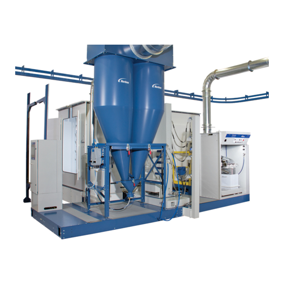
Page 18: Feed Center
When the color change is complete, the damper is partially closed since full flow is not required during normal operation. The operator can also open the damper manually as desired. Part 1605397-04 E 2015 Nordson Corporation... - Page 19 Description Figure 2-4 Encore Feed Center Components (shown with optional hose manifolds on lances) Part 1605397-04 E 2015 Nordson Corporation...
-
Page 20: Automatic Gun Movers/Gun Blow-Off
Move the spray guns into or out of the canopy. The positioners can be manually operated or electrically driven automatic devices. Automatic positioner movement is controlled by the Nordson iControlr system or Axis Controller. During production, the positioners maintain the set gun-to-part distance settings, following the contours of the parts. -
Page 21: Afterfilter
Boxes pulse valve timer panel. NOTE: The afterfilter may have either deflagration vents or an explosion suppression system. Contact your Nordson representative for information about explosion venting or suppression equipment. Afterfilter Operation See Figure 2-6. Powder is conveyed through the intake duct (5) into the collector section, where powder collects on the external surfaces of the cartridge filters (7). - Page 22 At 2.5-in. wc, a red warning light on the system control panel lights. At 3-in. wc, the entire system shuts down. Typically, the afterfilter is equipped with quick-acting explosion and fire suppression systems. These are not shown here. Part 1605397-04 E 2015 Nordson Corporation...
-
Page 23: Control Panels
Selects hopper or box, controls where lances stop when lowered into powder. Select 11. Color Change Off: Color change cycle is disabled Indicator Light Blinking: In color change cycle. On: Color change automatic operations complete. (Green) Part 1605397-04 E 2015 Nordson Corporation... - Page 24 2-14 Description Figure 2-7 Powder Feed Center Controls Part 1605397-04 E 2015 Nordson Corporation...
-
Page 25: Main Electrical Control Panel
11. ANCILLARY Lights amber when the ancillary equipment clean function is active. Turns the ancillary clean function to OFF when pushed. EQUIPMENT CLEAN and RESET ANC EQUI RESET Electrical Figure 2-8 Main Control Panel Part 1605397-04 E 2015 Nordson Corporation... -
Page 26: Typical System Options
Move the spray guns in repetitive vertical patterns for thorough part coverage. or Reciprocators Oscillators are typically controlled from the system control panel. Reciprocators are controlled by a Nordson iControl system, Axis controller, or PLC. Powder Drum Transfer virgin powder from shipping boxes, drums, or bags to the powder Unloaders feed center. -
Page 27: Operation
The PLCs in the powder feed center and the main electrical control panel control the automatic processes in a typical system. The PLCs are typically programmed by your Nordson application engineer to suit your application requirements. Spray gun triggering and the movement of positioners and reciprocators are typically controlled by a Nordson iControl Integrated Control system. -
Page 28: Typical Operating Settings
Lance Fluidizing Air 0.3−0.7 bar (5−10 psi) Timer Board Settings Table 3-6 Typical Timer Board Settings Timer Setting Afterfilter Cartridge Filter Pulsing On Time (Duration) 0.07 seconds Off Time (Delay) 10 − 12 seconds Part 1605397-04 E 2015 Nordson Corporation... -
Page 29: Booth Control Functions
Zones 1 − 4 time for zones 1 − 4. seconds (150ms) SCREEN 4 Blow-Off Zone Settings, Sets the blow-off zone ON 0.15 Zones 5 − 8 time for zones 5 − 8. seconds (150ms) Part 1605397-04 E 2015 Nordson Corporation... - Page 30 5.00 Fluidizing Duration the after filter vibrate and seconds fluidizing function. SCREEN 8 After Filter Vibrate and Sets the delay time for the 10:00 Fluidizing Cycle Delay after filter vibrate and minutes fluidizing cycle. Part 1605397-04 E 2015 Nordson Corporation...
- Page 31 AeroDeck ON time and the calculated OFF time. This screen is updated if the user values from Screen 5 and 6 are changed, and the FLOOR CLEAN selector switch is toggled OFF then ON. Part 1605397-04 E 2015 Nordson Corporation...
-
Page 32: Changing Function Values
7. Press the the OK key to enter the value. 8. Make additional changes to the same page by moving the cursor as described in steps 4−7. 9. When data changes to the page are complete, press the ESC key twice. Part 1605397-04 E 2015 Nordson Corporation... -
Page 33: Startup
Adjust the fluidizing air pressure, using the regulator on the side of the feed center. The powder should be gently boiling without geysering out of the powder source. Allow the powder to fluidize for several minutes before starting production. Turn on the powder sieve. Part 1605397-04 E 2015 Nordson Corporation... - Page 34 NOTE: It is important that the inside surface of the canopy is not touched by bare hands. Skin oils and other contaminants will affect the ability of the canopy to shed powder. Operators should wear cotton gloves when working with the canopy. Part 1605397-04 E 2015 Nordson Corporation...
-
Page 35: Ancillary Equipment Clean Function
The two operators’ tasks should be performed at the same time unless otherwise noted. Refer to the foldouts included as a supplement to this manual for step-by-step procedures. Note that the procedures are recommendations only and can be modified as desired. Part 1605397-04 E 2015 Nordson Corporation... -
Page 36: Powder Level Sensor Operation
Duct Lifter Close button. The cyclones connect to the afterfilter inlet duct. 8. When EXHAUSTER READY is displayed on the booth moving menu, touch the Exhauster Start button. The afterfilter exhaust fan starts. Part 1605397-04 E 2015 Nordson Corporation... -
Page 37: Shutdown
Press the SYSTEM STOP button on the system control panel. b. Turn the disconnect switches on the powder feed center, main electrical control panel, and afterfilter control panels to the OFF position. Part 1605397-04 E 2015 Nordson Corporation... - Page 38 3-12 Operation Part 1605397-04 E 2015 Nordson Corporation...
-
Page 39: Maintenance
NOTE: It is important that the inside surface of the canopy is not touched by bare hands. Skin oils and other contaminants will affect the ability of the canopy to shed powder during blowoff. Operators should wear cotton gloves when working with the canopy. Part 1605397-04 E 2015 Nordson Corporation... -
Page 40: Daily Maintenance
Drain the filters and separators and check the filter elements. Check all air pressure regulator settings. NOTE: The air dryer should remain on at all times to prevent moisture from accumulating in the compressed air system. Continued... Part 1605397-04 E 2015 Nordson Corporation... - Page 41 The resistance between the workpieces and the hangers, and the hangers and ground, must be less than 1 megohm. Use a megohm meter to check resistances. You will get better transfer efficiency and workpiece coverage at 500 ohms or less. Clean the hangers regularly. Part 1605397-04 E 2015 Nordson Corporation...
-
Page 42: Weekly Maintenance
Failure to observe this warning could result in a fire or explosion, causing property damage and possible personal injury or death. Check all equipment grounds. Repair or replace unconnected or damaged ground cables. Part 1605397-04 E 2015 Nordson Corporation... -
Page 43: Booth Canopy Conditioning
NOTE: It is important that the canopy is not touched by bare hands. Skin oils and other contaminants will affect the ability of the canopy to shed powder during blowoff. Operators should wear cotton gloves when working with the canopy. Part 1605397-04 E 2015 Nordson Corporation... -
Page 44: Cyclone Cleaning
7. Open the transfer pan and remove the remaining cyclone cleaning media. 8. Close the transfer pan. 9. Load a new powder color and reclaim to waste for 1−2 minutes to cleanse the system of the cyclone cleaning media residue. Part 1605397-04 E 2015 Nordson Corporation... -
Page 45: Hdlv Transfer Pump And Transfer Pan Maintenance
Periodically blow off the fluidizing plate and inspect it for signs of air contamination. If the plate is discolored and appears to be contaminated, replace it. Refer to Transfer Pan Cleaning for replacement instructions. Check your air supply and correct any contamination problems. Part 1605397-04 E 2015 Nordson Corporation... -
Page 46: Transfer Pan Cleaning
3. Install the sealing washer (4) and jam nut (8) onto the end of the discharge tube. Tighten the jam nut snugly using two wrenches: one on the flats of the discharge tube and the other on the jam nut. Do not over tighten the jam nut. Part 1605397-04 E 2015 Nordson Corporation... - Page 47 1. Fluidizing plate 7. Bulkhead union 2. Gasket 8. Jam nut 3. Plenum 9. Nuts 4. Sealing washer 10. Bolts 5. Discharge tube 11. Transfer pan 6. 16-mm transfer line 12. Fluidizing air tubing Part 1605397-04 E 2015 Nordson Corporation...
-
Page 48: Emptying The Afterfilter Waste Hoppers
Emptying the Waste Hoppers 1. After filter vent stub 4. Ground clamp 7. Lid vent stub 2. Vent hose 5. 55-Gallon drum 8. Waste lid 3. Transfer pumps 6. Hose connectors -in. Transfer hoses Part 1605397-04 E 2015 Nordson Corporation... -
Page 49: Maintenance Check List
Clean the fire detector head lenses every 4 hours. As required. Continuously monitor the workpiece clearance. **** Frequency varies depending on application. Check more frequently if spraying to waste often. Every 6 Lubrication months Roll-on/roll-off wheel bearings Fan and motor bearings Part 1605397-04 E 2015 Nordson Corporation... - Page 50 4-12 Maintenance Part 1605397-04 E 2015 Nordson Corporation...
-
Page 51: Troubleshooting
These procedures cover only the most common problems that you may encounter. If you cannot solve the problem with the information given here, contact your local Nordson representative for help. Common Problems Use the following tables to correct common problems with the Colormax 2 powder coating system. Problem Page Spray guns are surging or spitting;... - Page 52 Hose should be no longer than 7.6 m (25 ft) with a maximum 2.7-m (9-ft) vertical rise. Severe tribo-charging in powder Contact your Nordson Corporation feed hose representative for a suitable hose material. Contact your powder supplier.
- Page 53 Replace the cartridges if the gaskets or filter media are damaged. Replace clogged final filters. Leaks in collector housing allowing Locate and seal any leaks with RTV powder to bypass filters sealant. Continued... Part 1605397-04 E 2015 Nordson Corporation...
- Page 54 Fuse(s) blown Check the fuses in the system control panel. Replace the blown fuse(s). If the fuses continue to blow, fix the electrical problem. Electrical failure Trace the circuits and correct the problem. Continued... Part 1605397-04 E 2015 Nordson Corporation...
- Page 55 Canopy openings too large Close or decrease the size of the openings. Workpieces too large for booth Contact your Nordson Corporation representative. Exhaust fan rotation backward Reverse the rotation of the motor. Refer to the Reversing Motor Direction procedure in this section.
-
Page 56: Reversing Motor Direction
(L1, L2, or L3) connected to the live side of the fan motor circuit breaker. Close the panel door. 5. Turn the disconnect switches to the ON position. Start the fan and check the rotation direction. Part 1605397-04 E 2015 Nordson Corporation... -
Page 57: Repair
Follow the safety instructions in this document and all other related documentation. WARNING: Parts specified on the Nordson parts list must be used. Substitution of these parts could create a hazardous situation. These parts include but are not limited to the filters. -
Page 58: Filter Installation
7. Slip the ends of the mounting bracket into the locating slots around the filter opening in the mounting plate. 8. Tighten the nut until the mounting and centering brackets are touching. This will compress the filter gasket (11) and seal the cartridge against the mounting plate. Part 1605397-04 E 2015 Nordson Corporation... - Page 59 Cartridge Filter Replacement 1. Blow-down section 5. Flat washer 9. Centering bracket 2. Cartridge filter section 6. Mounting bracket 10. Cartridge filter 3. Hex nut 7. Mounting plate 11. Gasket 4. Lock washer 8. Draw rod Part 1605397-04 E 2015 Nordson Corporation...
-
Page 60: Seasoning The Cartridge Filters
8. Record the average air velocity across the booth part openings using a hand-held velometer. 9. Record the cartridge filter and final filter static pressure displayed on the pressure gauge. Part 1605397-04 E 2015 Nordson Corporation... -
Page 61: Final Filter Replacement
8. Install the final filter brackets and clamping knobs. 9. Tighten the clamping knobs to compress the final filter evenly on all four sides. Figure 6-2 Final Filter Replacement 1. Clamping knobs 3. Final filters 4. Fan housing 2. Final filter brackets Part 1605397-04 E 2015 Nordson Corporation... -
Page 62: Pulse Valve Replacement
10. Connect the air tubing to the pulse valve elbow fitting. Figure 6-3 Pulse Valve Replacement 1. Access door 4. Pulse valve 2. Nipple 5. Nozzle 3. Elbow fitting Part 1605397-04 E 2015 Nordson Corporation... -
Page 63: Parts
Parts Section 7 Parts Introduction To order parts, call the Nordson Industrial Coating Systems Customer Support Center at (800) 433-9319 or your local Nordson representative. Use the illustrations and parts lists to locate and describe parts correctly. Part 1605397-04 E 2015 Nordson Corporation... -
Page 64: Afterfilter Parts
C: Part used for afterfilter CFM 15750. NS: Not Shown AR: As Required Filters Afterfilter CFM Cartridge Filter P/N Quantity Required Final Filter P/N Quantity Required 9000 156996 156995 11250 156996 156995 15750 156996 156995 Part 1605397-04 E 2015 Nordson Corporation... - Page 65 Parts Figure 7-1 Afterfilter Parts Part 1605397-04 E 2015 Nordson Corporation...
-
Page 66: Gun Blow-Off Parts
Cyclone cleaning media, 50 lb drum −−−−−− Gun hose stand, floor mount (4 guns) −−−−−− Gun hose stand, roll on/roll off (4 guns) −−−−−− Kit, 36 inch, vertical extension, gun stand (adds 2 guns) Part 1605397-04 E 2015 Nordson Corporation... - Page 67 NOTE B: This part was used on the previous generation slidegate only. To differentiate the two, the new slidegate is identified by a yellow schematic label inside the slidegate junction box. NS: Not Shown Part 1605397-04 E 2015 Nordson Corporation...
- Page 68 Parts Figure 7-3 Slidegate Assembly Part 1605397-04 E 2015 Nordson Corporation...
-
Page 69: System Diagram
System Diagram Section 8 System Diagram Part 1605397-04 E 2015 Nordson Corporation... - Page 70 System Diagram Part 1605397-04 E 2015 Nordson Corporation...
- Page 71 CAN Network Ethernet and Discete Part NOTE: You system may not have all Denotes: CAN Field Connection Ethernet Network ID to Booth #2 options shown here. Figure 8-1 System Layout, ColorMax with Encore Feed Center Part 1605397-04 E 2015 Nordson Corporation...
Need help?
Do you have a question about the ColorMax 2 and is the answer not in the manual?
Questions and answers