Table of Contents
Advertisement
Quick Links
บริ ษ ั ท เอดี ด ี เฟอร์ เ นส จํ า กั ด
ADD FURNACE CO.,LTD.
44
70
ซอยบรมราชชนนี
: 02-888-3472
โทร
โทร
https://www.add-furnace.com E-mail: sales@add-furnace.com
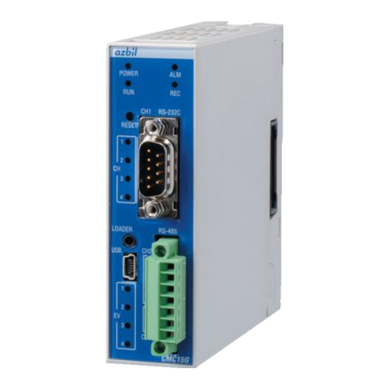
CMC15G
Multifunction Gateway
Communication Controller
User's
for Installation
ถนนบรมราชชนนี แขวงศาลาธรรมสพน์ เขตทวี ว ั ฒ นา กรุ ง เทพฯ
:
:08-08-170-170
: 02-888-3258
ออกแบบ
แฟกซ์
Manual
& Configuratio
Thank you for purchasing the CMC15G
Multifunction Gateway Communication
Controller .
This manual contains information for
ensuring
CMC15G. It also provides necessary
information
nance, and troubleshooting.
This manual should be read by those
who design and maintain equipment
that uses the CMC15G. Be sure to keep
this manual nearby for handy reference.
10170
No. CP-SP-1277E
the
correct
use
of
for
installation,
mainte-
the
Advertisement
Table of Contents

Subscribe to Our Youtube Channel
Related Manuals for Azbil CMC15G


Summary of Contents for Azbil CMC15G
- Page 1 This manual contains information for ensuring correct CMC15G. It also provides necessary information installation, mainte- nance, and troubleshooting. This manual should be read by those who design and maintain equipment that uses the CMC15G. Be sure to keep this manual nearby for handy reference.
- Page 2 If you should find an error or omis- sion, please contact the azbil Group. In no event is Azbil Corporation liable to anyone for any indirect, special or consequential damages as a result of using this product.
-
Page 3: Conventions Used In This Manual
Be sure to follow the indicated instructions. Handling Precautions Handling Precautions indicate items that the user should pay attention to when handling the CMC15G. Note Notes indicate information that might benefit the user. This indicates the item or page that the user is requested to refer to. -
Page 4: Safety Precautions
Prevent the total power consumption of all linked modules from exceeding 100 W. Before removing, mounting, or wiring the CMC15G, be sure to turn off the power to the CMC15G and allconnected devices. Failure to do so might cause electric shock. -
Page 5: The Role Of This Manual
The Role of This Manual A total of four different manuals are available for the CMC15G. Read them as necessary for your specific require- ments. If a manual you require is not available, contact the azbil Group or its dealer. - Page 6 GatewayEditor that is a set tool of the CMC15G. Chapter 9. WORKING WITH GATEWAYEDITOR This chapter describes a setting method and a set item to operate the CMC15G in the GatewayEditor. Chapter 10 CONNECTING TO THE CMC15G WITH GATEWAYEDITOR When the GatewayEditor is connected with the CMC15G with USB, this chapter describes the method of installing a necessary device driver.
- Page 7 This chapter describes the method of exchanging the backup batteries. Chapter 14. SPECIFICATIONS This chapter describes the general specifications and external dimensions of the CMC15G. Chapter 15. TROUBLESHOOTING This chapter describes the cause investigation of the trouble and the treatment method generated in using the CMC15G.
- Page 8 • • • • • • • • • • • • • • • • • • • • • • • • • • • • • • • • • • • • • • • • • • • • • • • • • • • • • • • ■ CMC15G •...
-
Page 9: Table Of Contents
บริ ษ ั ท เอดี ด ี เฟอร์ เ นส จํ า กั ด ADD FURNACE CO.,LTD. 10170 ซอยบรมราชชนนี ถนนบรมราชชนนี แขวงศาลาธรรมสพน์ เขตทวี ว ั ฒ นา กรุ ง เทพฯ : 02-888-3472 :08-08-170-170 : 02-888-3258 โทร โทร ออกแบบ แฟกซ์ https://www.add-furnace.com E-mail: sales@add-furnace.com ■... - Page 10 บริ ษ ั ท เอดี ด ี เฟอร์ เ นส จํ า กั ด ADD FURNACE CO.,LTD. 10170 ซอยบรมราชชนนี ถนนบรมราชชนนี แขวงศาลาธรรมสพน์ เขตทวี ว ั ฒ นา กรุ ง เทพฯ : 02-888-3472 :08-08-170-170 : 02-888-3258 โทร โทร ออกแบบ แฟกซ์ https://www.add-furnace.com E-mail: sales@add-furnace.com ■...
- Page 11 • • • • • • • • • • • • • • • • • • • • • • • • • • • • • • • • • • • • • • • • • • • • • • • • • • Chapter 10. CONNECTING TO THE CMC15G WITH GATEWAYEDITOR...
- Page 12 • • • • • • • • • • • • • • • • • • • • • • • • • • • • • • • • • • • • • • • • • • Chapter 12. CONTACTS AND REGISTERS INSIDE THE CMC15G ■...
- Page 13 บริ ษ ั ท เอดี ด ี เฟอร์ เ นส จํ า กั ด ADD FURNACE CO.,LTD. 10170 ซอยบรมราชชนนี ถนนบรมราชชนนี แขวงศาลาธรรมสพน์ เขตทวี ว ั ฒ นา กรุ ง เทพฯ : 02-888-3472 :08-08-170-170 : 02-888-3258 โทร โทร ออกแบบ แฟกซ์ https://www.add-furnace.com E-mail: sales@add-furnace.com Chapter 13.
-
Page 15: Overview And Features
CMC15G. If the CMC15G advanced function model is used, data can be saved from connect- ed modules (trend, data log, and event log) to the internal memory. To transmit saved data from the CMC15G's internal memory, a special PC loader tool, the LogViewer (model No. - Page 16 Chapter 1. OVERVIEW ■ Features • Easy installation and management The CMC15G is ready for operation, after simple setting of parameters using GatewayEditor. It is not necessary to create a communication program. Additionally, this multifunction gateway can flexibly accommodate design changes, and can be used to easily manage or reuse applications.
-
Page 17: Model Number Guide
: 02-888-3472 :08-08-170-170 : 02-888-3258 โทร โทร ออกแบบ แฟกซ์ https://www.add-furnace.com E-mail: sales@add-furnace.com Chapter 1. OVERVIEW 1 - 2 Model Number Guide ■ CMC15G Basic Model No. Function Module Option Specifications CMC15G Basic model Advanced model Base module with connectors None * To use the logging function, the CMC15GD01 advanced model is required. -
Page 18: Function Overview
This data transmission function shares information between modules connected to the CMC15G. This function reads data from the slave station (such as a controller) periodically and transmits it to the host station (such as a PLC), or it transmits data from the host station to the slave station upon activation of a host station trigger. - Page 19 With GatewayEditor, it is also possible to write data in the units used by the modules. For each module, the setup data that has been registered in the CMC15G is written to the module when the trigger turns ON (or OFF). This function makes it possible to automate the setup of the controller.
-
Page 20: Handling Precautions
● Continuous trend This function reads numeric data from connected modules at constant intervals and records the data. Data is saved in the internal memory of the CMC15G.This func- tion can be used to monitor, at constant intervals, changes in value. - Page 21 This function records data from connected modules in the internal memory of the CMC15G whenever a change in a specified bit occurs. The status data for connect- ed modules for one operation cycle can be saved at a specified time, such as when the system batch process begins, or when an error occurs in a connected module.
- Page 22 If an error occurs in communications with the connected module, this function notifies the host station. • Date and time adjustment This function sets the clock of the CMC15G based on the clock data of the host station. ● Option configuration •...
- Page 23 Parameter setting by SLP-D10 Handling Precautions • To execute the loader through-communication, other communication or data collection is stopped and the CMC15G is put in STOP mode. • Loaders capable of loader-through communications include Yamatake's Smart Loader Package models SLP-D10, SLP-C35, SLP-...
-
Page 25: Part Names And Functions
SG (CH2,3) is ON, and green while input is DA (CH3) ON. EV1-EV4 lamps all blink at the CMC15G DB (CH3) same time if operating power voltage is low. The digital signal I/O bus is connected to the DMC by side When power turns ON, the following connectors. - Page 26 CH2: RDA CH2: RDB SG: Signal ground CH2, 3:SG CH3: DA DA: Send and receive data (+) (CMC15G connected module) CH3: DB DB: Send and receive data (–) (CMC15G connected module) SG: Signal ground CMC15G ● CH4: RS-485 (3-wire) DC24V + DA: Send and receive data (+) (CMC15G ...
- Page 27 CMC15G. • The delay time of the digital signal output from the CMC15G may vary depending on the processing load. Allow sufficient time when checking...
- Page 28 Trend recording status CH1 RS-232C The meaning of the main unit LED indicators is as follows. • POWER indicator This indicator is used to check the power supply status of the CMC15G main unit. Status Meaning CMC15G power is OFF. Green CMC15G power is ON.
-
Page 29: Reset Switch
EV2 input/output EV3 input/output EV4 input/output CMC15G When the DMC10 is connected to the CMC15G, these indicators show the status of the four digital signal inputs and outputs for the event bus outputs and external switch inputs of the DMC10. Status Meaning No digital signal inputs or outputs. - Page 30 บริ ษ ั ท เอดี ด ี เฟอร์ เ นส จํ า กั ด ADD FURNACE CO.,LTD. 10170 ซอยบรมราชชนนี ถนนบรมราชชนนี แขวงศาลาธรรมสพน์ เขตทวี ว ั ฒ นา กรุ ง เทพฯ : 02-888-3472 :08-08-170-170 : 02-888-3258 โทร โทร ออกแบบ แฟกซ์ https://www.add-furnace.com E-mail: sales@add-furnace.com Chapter 2.
-
Page 31: Linking Modules
• Locations near flammable liquid or steam • Outdoors ■ Linking modules The CMC15G can be linked with other modules by the connectors on the left and right of the base. Modules must be linked before the CMC15G is mounted on the DIN rail or mount- ed by screws. - Page 32 บริ ษ ั ท เอดี ด ี เฟอร์ เ นส จํ า กั ด ADD FURNACE CO.,LTD. 10170 ซอยบรมราชชนนี ถนนบรมราชชนนี แขวงศาลาธรรมสพน์ เขตทวี ว ั ฒ นา กรุ ง เทพฯ : 02-888-3472 :08-08-170-170 : 02-888-3258 โทร โทร ออกแบบ แฟกซ์ https://www.add-furnace.com E-mail: sales@add-furnace.com Chapter 3.
- Page 33 บริ ษ ั ท เอดี ด ี เฟอร์ เ นส จํ า กั ด ADD FURNACE CO.,LTD. 10170 ซอยบรมราชชนนี ถนนบรมราชชนนี แขวงศาลาธรรมสพน์ เขตทวี ว ั ฒ นา กรุ ง เทพฯ : 02-888-3472 :08-08-170-170 : 02-888-3258 โทร โทร ออกแบบ แฟกซ์ https://www.add-furnace.com E-mail: sales@add-furnace.com Chapter 4 WIRING ■...
- Page 34 โทร โทร ออกแบบ แฟกซ์ https://www.add-furnace.com E-mail: sales@add-furnace.com Chapter 4. WIRING ■ Connecting for CH1 communications (RS-232C) Connect the cable to the D-Sub 9-pin connector on the CMC15G. Pin No. Signal Contents 1 *1 Not used Receive data (connected module CMC15G)
- Page 35 • When used with the DMC10, a maximum of 15 units can be directly connected, due to the limitation of the rotary switch. ● When connecting 31 or more units To connect more than 31 Azbil Corporation devices to each channel, the CMC10B communication controller (CPL/CPL converter, sold separately) is required. Handling Precautions •...
-
Page 36: Setting The Device Address
● Connection of Azbil Corporation devices through the CMC10B It is necessary also to set up a device address for each device connected through the CMC10B. These addresses are handled as sub-addresses by the CMC15G. Device address 1 Device address 1 to 6... - Page 37 Handling Precautions • Within a single group of units connected by side connectors, there can be only one event output module by which output can be done from the CMC15G. ● Position of event output module DMC10E DMC10E...
-
Page 39: Chapter 5. Basic Functions
5 - 1 Data Transmission This data transmission function exchanges data among modules connected to the CMC15G. Data is read from slave stations (controllers, etc.) periodically and written to the host station (PLC, etc.), or else data from the host station is written to the slave stations upon activation of a trigger at the host station. -
Page 40: Handling Precautions
Cyclic execution begins at constant intervals. There are two startup methods, cyclic (auto) and cyclic (fixed). • Cyclic (auto): The CMC15G determines an execution interval based on the average processing time. • Cyclic (fixed): Cyclic execution begins at user-specified intervals. -
Page 41: Triggers
CH3 SP D0102 CH4 SP D0103 (1) The CMC15G monitors the trigger device periodically. After the trigger device is turned ON, the trigger is executed. (2) Data is read from the source. (3) The data is written to the destination. - Page 42 บริ ษ ั ท เอดี ด ี เฟอร์ เ นส จํ า กั ด ADD FURNACE CO.,LTD. 10170 ซอยบรมราชชนนี ถนนบรมราชชนนี แขวงศาลาธรรมสพน์ เขตทวี ว ั ฒ นา กรุ ง เทพฯ : 02-888-3472 :08-08-170-170 : 02-888-3258 โทร โทร ออกแบบ แฟกซ์ https://www.add-furnace.com E-mail: sales@add-furnace.com Chapter 5.
-
Page 43: Module Setup
5 - 2 Module Setup This function writes fixed data (values stored in the CMC15G) to connected modules. It can be used, upon instructions from the host station, for tasks such as changing the mode (RUN/READY) of a controller or other slave station or initializing the settings of a connected module. -
Page 44: Triggers
● Process The following describes the operation to write the initial values (data) set for the CMC15G to a connected module when the specified trigger device on the host sta- tion is changed from OFF to ON: (1) Trigger device is turned ON... -
Page 45: Internal Event
This internal event function monitors the status of a bit or numeric value on a connected module in order to deter- mine whether to turn ON or OFF a corresponding bit inside the CMC15G. The information output to the internal bit can be utilized for locations shown below. -
Page 46: Group
บริ ษ ั ท เอดี ด ี เฟอร์ เ นส จํ า กั ด ADD FURNACE CO.,LTD. 10170 ซอยบรมราชชนนี ถนนบรมราชชนนี แขวงศาลาธรรมสพน์ เขตทวี ว ั ฒ นา กรุ ง เทพฯ : 02-888-3472 :08-08-170-170 : 02-888-3258 โทร โทร ออกแบบ แฟกซ์ https://www.add-furnace.com E-mail: sales@add-furnace.com Chapter 5. -
Page 47: Execution Conditions And Processing For Each Function
Cyclic execution operates continuously at specified intervals. There are two kinds of cyclic execution, auto and fixed. • Cyclic (auto): The CMC15G determines an execution interval based on the average processing time. • Cyclic (fixed): Cyclic execution begins at intervals specified by the user (in "s"... -
Page 48: Enabled-Disabled Setting
บริ ษ ั ท เอดี ด ี เฟอร์ เ นส จํ า กั ด ADD FURNACE CO.,LTD. 10170 ซอยบรมราชชนนี ถนนบรมราชชนนี แขวงศาลาธรรมสพน์ เขตทวี ว ั ฒ นา กรุ ง เทพฯ : 02-888-3472 :08-08-170-170 : 02-888-3258 โทร โทร ออกแบบ แฟกซ์ https://www.add-furnace.com E-mail: sales@add-furnace.com Chapter 5. -
Page 49: Sequential Execution
• Share application software used for the system. • Take only specific controllers offline. POWER CH1 RS-232C RESET LOADER RS-485 Bit settings of PLC CMC15G M000 Communication group 1 Controller 1 enabled M001 Communication group 2 Controller 2 enabled CMC15G... - Page 50 E-mail: sales@add-furnace.com Chapter 5. BASIC FUNCTIONS • Operation flow (1) The CMC15G monitors the bit periodically. If the bit is changed to ON, the sequential execution function is started. (2) The READY constant is written to the RUN/READY address.
-
Page 51: Notification Process
บริ ษ ั ท เอดี ด ี เฟอร์ เ นส จํ า กั ด ADD FURNACE CO.,LTD. 10170 ซอยบรมราชชนนี ถนนบรมราชชนนี แขวงศาลาธรรมสพน์ เขตทวี ว ั ฒ นา กรุ ง เทพฯ : 02-888-3472 :08-08-170-170 : 02-888-3258 โทร โทร ออกแบบ แฟกซ์ https://www.add-furnace.com E-mail: sales@add-furnace.com Chapter 5. - Page 52 CMC15G sets the bit Completion notification Reset by host station as necessary Error notification CMC15G sets the bit only if an error occurs When set for notification (with initialization) of completion and errors Execution cycle Execution cycle Process, such as data...
- Page 53 Completion notification Reset by host station as necessary Error notification CMC15G sets the bit only if an error occurs Note: After the trigger (without initialization) is turned ON, it must be turned OFF by the host station. Trigger (with initialization), log entry at trigger start, notification (with initialization) of completion...
- Page 54 • When using a trigger (with initialization), you must set the trigger device once through the host station (such as a PLC). If a device that is always running, such as an output coil, is used the trigger cannot be initialized by the CMC15G. Correct example Startup condition...
-
Page 55: Communication Error
บริ ษ ั ท เอดี ด ี เฟอร์ เ นส จํ า กั ด ADD FURNACE CO.,LTD. 10170 ซอยบรมราชชนนี ถนนบรมราชชนนี แขวงศาลาธรรมสพน์ เขตทวี ว ั ฒ นา กรุ ง เทพฯ : 02-888-3472 :08-08-170-170 : 02-888-3258 โทร โทร ออกแบบ แฟกซ์ https://www.add-furnace.com E-mail: sales@add-furnace.com Chapter 5. -
Page 57: Chapter 6. Logging Function
Continuous Trend This function reads out numeric data from connected modules periodically and records it to the internal memory of the CMC15G. The continuous trend function can be used to monitor, at constant intervals, changes in values. ■ Description of operation ●... -
Page 58: Operation If An Error Occurs
If any of the following conditions arises, the record is not recorded during this period. (A separating vertical line is displayed on the LogViewer.) • The CMC15G is turned OFF. • Read-out is stopped by a change in the enabled-disabled setting. -
Page 59: Captured Trends Function
The captured trends function reads numeric data from connected modules periodically. When a trigger occurs, it saves data from before and after the trigger to the internal memory of the CMC15G. Waveform information from before and after the occurrence of an alarm is kept and can be used for analysis during maintenance work. -
Page 60: Handling Precautions
บริ ษ ั ท เอดี ด ี เฟอร์ เ นส จํ า กั ด ADD FURNACE CO.,LTD. 10170 ซอยบรมราชชนนี ถนนบรมราชชนนี แขวงศาลาธรรมสพน์ เขตทวี ว ั ฒ นา กรุ ง เทพฯ : 02-888-3472 :08-08-170-170 : 02-888-3258 โทร โทร ออกแบบ แฟกซ์ https://www.add-furnace.com E-mail: sales@add-furnace.com Chapter 6. - Page 61 If any of the following conditions arises, the record is not recorded during this period. (A separating vertical line is displayed on the LogViewer.) • The CMC15G is turned OFF. • Read-out is stopped by a change in the enabled-disabled setting.
-
Page 62: Data Log
Data Log The data log function records information from the connected modules in the internal memory of the CMC15G when a change in the bit is detected. Status data from the connected modules for one cycle is saved if a system batch process is started or if an error occurs in the connected modules. - Page 63 บริ ษ ั ท เอดี ด ี เฟอร์ เ นส จํ า กั ด ADD FURNACE CO.,LTD. 10170 ซอยบรมราชชนนี ถนนบรมราชชนนี แขวงศาลาธรรมสพน์ เขตทวี ว ั ฒ นา กรุ ง เทพฯ : 02-888-3472 :08-08-170-170 : 02-888-3258 โทร โทร ออกแบบ แฟกซ์ https://www.add-furnace.com E-mail: sales@add-furnace.com Chapter 6.
-
Page 64: Event Log
When multiple bits are monitored and a change occurs, the following describes how the event and the date and time are saved: (1) Start of cycle (2) Data read out D1000 D2000 CMC15G D3000 Date & time Status Controller ( DMC10 ) (4) If the number of saved records... - Page 65 บริ ษ ั ท เอดี ด ี เฟอร์ เ นส จํ า กั ด ADD FURNACE CO.,LTD. 10170 ซอยบรมราชชนนี ถนนบรมราชชนนี แขวงศาลาธรรมสพน์ เขตทวี ว ั ฒ นา กรุ ง เทพฯ : 02-888-3472 :08-08-170-170 : 02-888-3258 โทร โทร ออกแบบ แฟกซ์ https://www.add-furnace.com E-mail: sales@add-furnace.com Chapter 6.
-
Page 66: Groups And Execution Conditions
บริ ษ ั ท เอดี ด ี เฟอร์ เ นส จํ า กั ด ADD FURNACE CO.,LTD. 10170 ซอยบรมราชชนนี ถนนบรมราชชนนี แขวงศาลาธรรมสพน์ เขตทวี ว ั ฒ นา กรุ ง เทพฯ : 02-888-3472 :08-08-170-170 : 02-888-3258 โทร โทร ออกแบบ แฟกซ์ https://www.add-furnace.com E-mail: sales@add-furnace.com Chapter 6. -
Page 67: Chapter 7. Extended Functions And Other Functions
EXTENDED FUNCTIONS AND OTHER FUNCTIONS 7 - 1 Status Notification This function sends a notification to the host station regarding the status of the CMC15G. ■ Running notification This function is used when the host station needs to confirm that the CMC15G is operating correctly. -
Page 68: Battery Alarm Notification
E-mail: sales@add-furnace.com Chapter 7. EXTENDED FUNCTIONS AND OTHER FUNCTIONS ■ Battery alarm notification This function notifies the host station regarding the battery status of the CMC15G. Battery alarm: Voltage level of the CMC15G's backup battery is below a speci- fied level. - Page 69 The capture and capture limit statuses are retained until the data is down- loaded or the recorded data is cleared. By monitoring the specified notification device, the status of the CMC15G can be checked. When alarm status occurs, the bit is turned ON at the intervals specified by the user (in "min"...
-
Page 70: Communication Error Notification
The communication error notification function sends notice of an error to the host station if an error occurs in com- munication between the CMC15G and a connected module. By monitoring a specified bit, the host station can check if there has been an error in communication with a connected module. -
Page 71: Date And Time Adjustment
Date and Time Adjustment This date and time adjustment function adjusts the year, month, day, hour, minute, and second data on the CMC15G to the date and time of the system. The settable date and time range is from 00:00:00 on January 1, 2000 to 23:59:59 on December 31, 2099. -
Page 72: Option Configuration
Trigger device initialization In trigger processing, normally the host station initializes the trigger device. However, if this is not desired, the CMC15G, when it starts up, can initialize trig- ger devices that have been changed to execution status. Functions that can be initialized are the basic data transmission and module setup functions. - Page 73 CH4 SP D0103 (2) Bit is reset. (1) The CMC15G monitors the trigger device periodically. After the trigger device is turned ON, the trigger is executed. (2) The trigger device is initialized (in this case, the bit is turned off).
-
Page 74: Initialization Of Completion Notification Device And Error
■ Initialization of completion notification device and error notification device This function initializes the completion notification device or error notification device specified by the CMC15G when a process of some function starts up. Normally, the host station initializes the notification device. However, if this is not desired, the CMC15G can initialize it. -
Page 75: Digital Signal Input/Output Bus
When utilizing the event bus output of the DMC10 as digital signal input of the CMC15G in a function setup, "BM0000*" (where "*" stands for a numeral from 0 to 3) is input to a memory address location. -
Page 76: Loader Through-Communication
7 - 6 Loader Through-Communication When ThroughComm is used as a tool for changing the CMC15G to THROUGH mode, the dedicated loader for any Azbil Corporation controller can be operated through the CMC15G. The dedicated loaders which can be con- nected include: •... - Page 77 >> The following window will appear: (2) Select the communication port (COM port) No. of the personal computer con- nected to the CMC15G in the [Comm Configuration] box. In this example, "COM port 4" is set. (3) Select the communication channel number to which the module is connected in the [CMC15G target CH] box.
- Page 78 แฟกซ์ https://www.add-furnace.com E-mail: sales@add-furnace.com Chapter 7. EXTENDED FUNCTIONS AND OTHER FUNCTIONS >> The CMC15G changes to through-communication mode. (6) The high-speed flashing of the RUN indicator on the front panel indicates that the mode has been changed successfully. (7) Start up the dedicated loader for each connected module. In this example, the SLP-C45 is started.
-
Page 79: Quitting Loader Through-Communication
Chapter 7. EXTENDED FUNCTIONS AND OTHER FUNCTIONS (9) Select the communication port (COM port) of the personal computer connected to the CMC15G in the "Communication Port" area. In this example, COM port 1 is selected. (10) Check on [Use CMC10L] in the "Communication Setup" area. - Page 80 • Click the [Stop] button in the ThroughComm window to change the mode to RUN mode. • Keep the RESET switch on the CMC15G pressed for at least 5 s. • Turn OFF the power, and then turn it ON again.
-
Page 81: Chapter 8. Gatewayeditor
*2. If GatewayEditor is started up in a language environment other than Japanese, the menus are displayed in English. *3. To communicate with the CMC15G, the personal computer must have either a USB or COM port interface. *4. Supported OS and version of GatewayEditor are as follows. -
Page 82: Installing Gatewayeditor
Installing GatewayEditor ■ Installing the SLP-G15 Handling Precautions • Do not connect the CMC15G and personal computer with the USB cable during installation. If they are connected, the USB drivers will not be installed correctly. (1) Insert GatewayEditor Setup CD-ROM into the CD-ROM drive. Click [Computer] to open it. - Page 83 บริ ษ ั ท เอดี ด ี เฟอร์ เ นส จํ า กั ด ADD FURNACE CO.,LTD. 10170 ซอยบรมราชชนนี ถนนบรมราชชนนี แขวงศาลาธรรมสพน์ เขตทวี ว ั ฒ นา กรุ ง เทพฯ : 02-888-3472 :08-08-170-170 : 02-888-3258 โทร โทร ออกแบบ แฟกซ์ https://www.add-furnace.com E-mail: sales@add-furnace.com Chapter 8.
- Page 84 บริ ษ ั ท เอดี ด ี เฟอร์ เ นส จํ า กั ด ADD FURNACE CO.,LTD. 10170 ซอยบรมราชชนนี ถนนบรมราชชนนี แขวงศาลาธรรมสพน์ เขตทวี ว ั ฒ นา กรุ ง เทพฯ : 02-888-3472 :08-08-170-170 : 02-888-3258 โทร โทร ออกแบบ แฟกซ์ https://www.add-furnace.com E-mail: sales@add-furnace.com Chapter 8.
- Page 85 Microsoft's WHQL (Windows Hardware Quality Labs) test for conformity to Windows standards. However, Azbil Corporation has conducted a complete functional check of these drivers. Therefore, continue the installation, since no problems will occur in the system if these drivers are installed.
-
Page 86: Uninstalling The Slp-G15
บริ ษ ั ท เอดี ด ี เฟอร์ เ นส จํ า กั ด ADD FURNACE CO.,LTD. 10170 ซอยบรมราชชนนี ถนนบรมราชชนนี แขวงศาลาธรรมสพน์ เขตทวี ว ั ฒ นา กรุ ง เทพฯ : 02-888-3472 :08-08-170-170 : 02-888-3258 โทร โทร ออกแบบ แฟกซ์ https://www.add-furnace.com E-mail: sales@add-furnace.com Chapter 8. -
Page 87: Slp-G15 Upgrade And Maintenance
บริ ษ ั ท เอดี ด ี เฟอร์ เ นส จํ า กั ด ADD FURNACE CO.,LTD. 10170 ซอยบรมราชชนนี ถนนบรมราชชนนี แขวงศาลาธรรมสพน์ เขตทวี ว ั ฒ นา กรุ ง เทพฯ : 02-888-3472 :08-08-170-170 : 02-888-3258 โทร โทร ออกแบบ แฟกซ์ https://www.add-furnace.com E-mail: sales@add-furnace.com Chapter 8. - Page 88 บริ ษ ั ท เอดี ด ี เฟอร์ เ นส จํ า กั ด ADD FURNACE CO.,LTD. 10170 ซอยบรมราชชนนี ถนนบรมราชชนนี แขวงศาลาธรรมสพน์ เขตทวี ว ั ฒ นา กรุ ง เทพฯ : 02-888-3472 :08-08-170-170 : 02-888-3258 โทร โทร ออกแบบ แฟกซ์ https://www.add-furnace.com E-mail: sales@add-furnace.com Chapter 8.
-
Page 89: Starting Up And Exiting Gatewayeditor
บริ ษ ั ท เอดี ด ี เฟอร์ เ นส จํ า กั ด ADD FURNACE CO.,LTD. 10170 ซอยบรมราชชนนี ถนนบรมราชชนนี แขวงศาลาธรรมสพน์ เขตทวี ว ั ฒ นา กรุ ง เทพฯ : 02-888-3472 :08-08-170-170 : 02-888-3258 โทร โทร ออกแบบ แฟกซ์ https://www.add-furnace.com E-mail: sales@add-furnace.com Chapter 8. -
Page 90: Operation Flow
E-mail: sales@add-furnace.com Chapter 8. GATEWAYEDITOR 8 - 4 Operation Flow Open Open project Create new project Open file. Module constitution Upload from CMC15G. Edit Configuration by function Auxiliary function System configuration Data transmit Address input support Module constitution Module setup... -
Page 91: Configuration Functions
Buttons related to menu items are displayed. ● Project view Function configuration items for the CMC15G are displayed in a tree view format. ● Function configuration tab sheet A configuration sheet for each function is displayed as a tab sheet in list format. -
Page 92: Menu Descriptions
บริ ษ ั ท เอดี ด ี เฟอร์ เ นส จํ า กั ด ADD FURNACE CO.,LTD. 10170 ซอยบรมราชชนนี ถนนบรมราชชนนี แขวงศาลาธรรมสพน์ เขตทวี ว ั ฒ นา กรุ ง เทพฯ : 02-888-3472 :08-08-170-170 : 02-888-3258 โทร โทร ออกแบบ แฟกซ์ https://www.add-furnace.com E-mail: sales@add-furnace.com Chapter 8. - Page 93 บริ ษ ั ท เอดี ด ี เฟอร์ เ นส จํ า กั ด ADD FURNACE CO.,LTD. 10170 ซอยบรมราชชนนี ถนนบรมราชชนนี แขวงศาลาธรรมสพน์ เขตทวี ว ั ฒ นา กรุ ง เทพฯ : 02-888-3472 :08-08-170-170 : 02-888-3258 โทร โทร ออกแบบ แฟกซ์ https://www.add-furnace.com E-mail: sales@add-furnace.com Chapter 8.
- Page 94 บริ ษ ั ท เอดี ด ี เฟอร์ เ นส จํ า กั ด ADD FURNACE CO.,LTD. 10170 ซอยบรมราชชนนี ถนนบรมราชชนนี แขวงศาลาธรรมสพน์ เขตทวี ว ั ฒ นา กรุ ง เทพฯ : 02-888-3472 :08-08-170-170 : 02-888-3258 โทร โทร ออกแบบ แฟกซ์ https://www.add-furnace.com E-mail: sales@add-furnace.com Chapter 8.
- Page 95 Reads out information (version or history) from the CMC15G main unit. Online monitor Displays the Online monitor screen, allowing you to check the process status of the CMC15G function or the status of communication with the connected modules. Online Mode change...
-
Page 96: Project View
Chapter 8. GATEWAYEDITOR 8-5-2 Project view Settings for CMC15G functions are displayed in a tree view format. You can configure each function from the project view. The CMC15GD01 advanced model displays the logging function items in addition to the items for the standard model. - Page 97 Settings for notifying the host station of the status of the CMC15G. • Comm Error Notification: Settings for notifying the host station of a com- munication error between the CMC15G and a connected module. • Data Time Adjustment: Settings for synchronization of CMC15G date and time with the date and time of the host sta- tion.
-
Page 98: Creating A Configuration Sheet
บริ ษ ั ท เอดี ด ี เฟอร์ เ นส จํ า กั ด ADD FURNACE CO.,LTD. 10170 ซอยบรมราชชนนี ถนนบรมราชชนนี แขวงศาลาธรรมสพน์ เขตทวี ว ั ฒ นา กรุ ง เทพฯ : 02-888-3472 :08-08-170-170 : 02-888-3258 โทร โทร ออกแบบ แฟกซ์ https://www.add-furnace.com E-mail: sales@add-furnace.com Chapter 8. -
Page 99: Opening A Configuration Sheet
บริ ษ ั ท เอดี ด ี เฟอร์ เ นส จํ า กั ด ADD FURNACE CO.,LTD. 10170 ซอยบรมราชชนนี ถนนบรมราชชนนี แขวงศาลาธรรมสพน์ เขตทวี ว ั ฒ นา กรุ ง เทพฯ : 02-888-3472 :08-08-170-170 : 02-888-3258 โทร โทร ออกแบบ แฟกซ์ https://www.add-furnace.com E-mail: sales@add-furnace.com Chapter 8. - Page 100 บริ ษ ั ท เอดี ด ี เฟอร์ เ นส จํ า กั ด ADD FURNACE CO.,LTD. 10170 ซอยบรมราชชนนี ถนนบรมราชชนนี แขวงศาลาธรรมสพน์ เขตทวี ว ั ฒ นา กรุ ง เทพฯ : 02-888-3472 :08-08-170-170 : 02-888-3258 โทร โทร ออกแบบ แฟกซ์ https://www.add-furnace.com E-mail: sales@add-furnace.com Chapter 8.
-
Page 101: Function Configuration Tab Sheet
บริ ษ ั ท เอดี ด ี เฟอร์ เ นส จํ า กั ด ADD FURNACE CO.,LTD. 10170 ซอยบรมราชชนนี ถนนบรมราชชนนี แขวงศาลาธรรมสพน์ เขตทวี ว ั ฒ นา กรุ ง เทพฯ : 02-888-3472 :08-08-170-170 : 02-888-3258 โทร โทร ออกแบบ แฟกซ์ https://www.add-furnace.com E-mail: sales@add-furnace.com Chapter 8. -
Page 102: Operating Procedures
บริ ษ ั ท เอดี ด ี เฟอร์ เ นส จํ า กั ด ADD FURNACE CO.,LTD. 10170 ซอยบรมราชชนนี ถนนบรมราชชนนี แขวงศาลาธรรมสพน์ เขตทวี ว ั ฒ นา กรุ ง เทพฯ : 02-888-3472 :08-08-170-170 : 02-888-3258 โทร โทร ออกแบบ แฟกซ์ https://www.add-furnace.com E-mail: sales@add-furnace.com Chapter 8. - Page 103 บริ ษ ั ท เอดี ด ี เฟอร์ เ นส จํ า กั ด ADD FURNACE CO.,LTD. 10170 ซอยบรมราชชนนี ถนนบรมราชชนนี แขวงศาลาธรรมสพน์ เขตทวี ว ั ฒ นา กรุ ง เทพฯ : 02-888-3472 :08-08-170-170 : 02-888-3258 โทร โทร ออกแบบ แฟกซ์ https://www.add-furnace.com E-mail: sales@add-furnace.com Chapter 8.
- Page 104 บริ ษ ั ท เอดี ด ี เฟอร์ เ นส จํ า กั ด ADD FURNACE CO.,LTD. 10170 ซอยบรมราชชนนี ถนนบรมราชชนนี แขวงศาลาธรรมสพน์ เขตทวี ว ั ฒ นา กรุ ง เทพฯ : 02-888-3472 :08-08-170-170 : 02-888-3258 โทร โทร ออกแบบ แฟกซ์ https://www.add-furnace.com E-mail: sales@add-furnace.com Chapter 8.
-
Page 105: Module Selection Palette And Address Selection Palette
บริ ษ ั ท เอดี ด ี เฟอร์ เ นส จํ า กั ด ADD FURNACE CO.,LTD. 10170 ซอยบรมราชชนนี ถนนบรมราชชนนี แขวงศาลาธรรมสพน์ เขตทวี ว ั ฒ นา กรุ ง เทพฯ : 02-888-3472 :08-08-170-170 : 02-888-3258 โทร โทร ออกแบบ แฟกซ์ https://www.add-furnace.com E-mail: sales@add-furnace.com Chapter 8. - Page 106 บริ ษ ั ท เอดี ด ี เฟอร์ เ นส จํ า กั ด ADD FURNACE CO.,LTD. 10170 ซอยบรมราชชนนี ถนนบรมราชชนนี แขวงศาลาธรรมสพน์ เขตทวี ว ั ฒ นา กรุ ง เทพฯ : 02-888-3472 :08-08-170-170 : 02-888-3258 โทร โทร ออกแบบ แฟกซ์ https://www.add-furnace.com E-mail: sales@add-furnace.com Chapter 8.
- Page 107 บริ ษ ั ท เอดี ด ี เฟอร์ เ นส จํ า กั ด ADD FURNACE CO.,LTD. 10170 ซอยบรมราชชนนี ถนนบรมราชชนนี แขวงศาลาธรรมสพน์ เขตทวี ว ั ฒ นา กรุ ง เทพฯ : 02-888-3472 :08-08-170-170 : 02-888-3258 โทร โทร ออกแบบ แฟกซ์ https://www.add-furnace.com E-mail: sales@add-furnace.com Chapter 8.
- Page 108 บริ ษ ั ท เอดี ด ี เฟอร์ เ นส จํ า กั ด ADD FURNACE CO.,LTD. 10170 ซอยบรมราชชนนี ถนนบรมราชชนนี แขวงศาลาธรรมสพน์ เขตทวี ว ั ฒ นา กรุ ง เทพฯ : 02-888-3472 :08-08-170-170 : 02-888-3258 โทร โทร ออกแบบ แฟกซ์ https://www.add-furnace.com E-mail: sales@add-furnace.com Chapter 8.
-
Page 109: Operating Procedures
บริ ษ ั ท เอดี ด ี เฟอร์ เ นส จํ า กั ด ADD FURNACE CO.,LTD. 10170 ซอยบรมราชชนนี ถนนบรมราชชนนี แขวงศาลาธรรมสพน์ เขตทวี ว ั ฒ นา กรุ ง เทพฯ : 02-888-3472 :08-08-170-170 : 02-888-3258 โทร โทร ออกแบบ แฟกซ์ https://www.add-furnace.com E-mail: sales@add-furnace.com Chapter 8. - Page 110 บริ ษ ั ท เอดี ด ี เฟอร์ เ นส จํ า กั ด ADD FURNACE CO.,LTD. 10170 ซอยบรมราชชนนี ถนนบรมราชชนนี แขวงศาลาธรรมสพน์ เขตทวี ว ั ฒ นา กรุ ง เทพฯ : 02-888-3472 :08-08-170-170 : 02-888-3258 โทร โทร ออกแบบ แฟกซ์ https://www.add-furnace.com E-mail: sales@add-furnace.com Chapter 8.
- Page 111 บริ ษ ั ท เอดี ด ี เฟอร์ เ นส จํ า กั ด ADD FURNACE CO.,LTD. 10170 ซอยบรมราชชนนี ถนนบรมราชชนนี แขวงศาลาธรรมสพน์ เขตทวี ว ั ฒ นา กรุ ง เทพฯ : 02-888-3472 :08-08-170-170 : 02-888-3258 โทร โทร ออกแบบ แฟกซ์ https://www.add-furnace.com E-mail: sales@add-furnace.com Chapter 8.
-
Page 112: Favorite List
บริ ษ ั ท เอดี ด ี เฟอร์ เ นส จํ า กั ด ADD FURNACE CO.,LTD. 10170 ซอยบรมราชชนนี ถนนบรมราชชนนี แขวงศาลาธรรมสพน์ เขตทวี ว ั ฒ นา กรุ ง เทพฯ : 02-888-3472 :08-08-170-170 : 02-888-3258 โทร โทร ออกแบบ แฟกซ์ https://www.add-furnace.com E-mail: sales@add-furnace.com Chapter 8. - Page 113 บริ ษ ั ท เอดี ด ี เฟอร์ เ นส จํ า กั ด ADD FURNACE CO.,LTD. 10170 ซอยบรมราชชนนี ถนนบรมราชชนนี แขวงศาลาธรรมสพน์ เขตทวี ว ั ฒ นา กรุ ง เทพฯ : 02-888-3472 :08-08-170-170 : 02-888-3258 โทร โทร ออกแบบ แฟกซ์ https://www.add-furnace.com E-mail: sales@add-furnace.com Chapter 8.
- Page 114 บริ ษ ั ท เอดี ด ี เฟอร์ เ นส จํ า กั ด ADD FURNACE CO.,LTD. 10170 ซอยบรมราชชนนี ถนนบรมราชชนนี แขวงศาลาธรรมสพน์ เขตทวี ว ั ฒ นา กรุ ง เทพฯ : 02-888-3472 :08-08-170-170 : 02-888-3258 โทร โทร ออกแบบ แฟกซ์ https://www.add-furnace.com E-mail: sales@add-furnace.com Chapter 8.
- Page 115 บริ ษ ั ท เอดี ด ี เฟอร์ เ นส จํ า กั ด ADD FURNACE CO.,LTD. 10170 ซอยบรมราชชนนี ถนนบรมราชชนนี แขวงศาลาธรรมสพน์ เขตทวี ว ั ฒ นา กรุ ง เทพฯ : 02-888-3472 :08-08-170-170 : 02-888-3258 โทร โทร ออกแบบ แฟกซ์ https://www.add-furnace.com E-mail: sales@add-furnace.com Chapter 8.
-
Page 116: List Of Configuration Errors
• No data was input. If there is a configuration error, the configuration cannot be transmitted to the CMC15G. To move to the portion having the configuration error, follow the steps below. (1) Double-click the line for which the error is displayed or select the relevant line and press the [Enter] key. -
Page 117: Chapter 9. Working With Gatewayeditor
WORKING WITH GATEWAYEDITOR 9 - 1 Creating a Project A project is a group of functional settings for the CMC15G. Once a project has been downloaded to the main unit, CMC15G functions are available. 9-1-1 Creating a new project • Procedures (1) Select [Create new project] from the [File] menu. -
Page 118: Opening A Project
บริ ษ ั ท เอดี ด ี เฟอร์ เ นส จํ า กั ด ADD FURNACE CO.,LTD. 10170 ซอยบรมราชชนนี ถนนบรมราชชนนี แขวงศาลาธรรมสพน์ เขตทวี ว ั ฒ นา กรุ ง เทพฯ : 02-888-3472 :08-08-170-170 : 02-888-3258 โทร โทร ออกแบบ แฟกซ์ https://www.add-furnace.com E-mail: sales@add-furnace.com Chapter 9 WORKING WITH GATEWAYEDITOR 9-1-2 Opening a project •... -
Page 119: Re-Opening A Project
บริ ษ ั ท เอดี ด ี เฟอร์ เ นส จํ า กั ด ADD FURNACE CO.,LTD. 10170 ซอยบรมราชชนนี ถนนบรมราชชนนี แขวงศาลาธรรมสพน์ เขตทวี ว ั ฒ นา กรุ ง เทพฯ : 02-888-3472 :08-08-170-170 : 02-888-3258 โทร โทร ออกแบบ แฟกซ์ https://www.add-furnace.com E-mail: sales@add-furnace.com Chapter 9 WORKING WITH GATEWAYEDITOR 9-1-3 Re-opening a project •... -
Page 120: Saving A Project
บริ ษ ั ท เอดี ด ี เฟอร์ เ นส จํ า กั ด ADD FURNACE CO.,LTD. 10170 ซอยบรมราชชนนี ถนนบรมราชชนนี แขวงศาลาธรรมสพน์ เขตทวี ว ั ฒ นา กรุ ง เทพฯ : 02-888-3472 :08-08-170-170 : 02-888-3258 โทร โทร ออกแบบ แฟกซ์ https://www.add-furnace.com E-mail: sales@add-furnace.com Chapter 9 WORKING WITH GATEWAYEDITOR 9-1-4 Saving a project ●... -
Page 121: Closing A Project
บริ ษ ั ท เอดี ด ี เฟอร์ เ นส จํ า กั ด ADD FURNACE CO.,LTD. 10170 ซอยบรมราชชนนี ถนนบรมราชชนนี แขวงศาลาธรรมสพน์ เขตทวี ว ั ฒ นา กรุ ง เทพฯ : 02-888-3472 :08-08-170-170 : 02-888-3258 โทร โทร ออกแบบ แฟกซ์ https://www.add-furnace.com E-mail: sales@add-furnace.com Chapter 9 WORKING WITH GATEWAYEDITOR 9-1-5 Closing a project •... -
Page 122: Checking The Project Information
Displays the date and time when the project was saved. ● Size of project (bytes) Displays the size of data saved to the CMC15G. If this size exceeds the maximum size (1048000 bytes), it is displayed in red. ● Number of operations Displays the total number of operations set for the data transmission or module setup, etc. -
Page 123: Outputting A Csv File
The contents of the project are output to a file in CSV format. ■ Output contents ● Project information Project name File name of project Model No. CMC15G*01A00 Comment Comment about the project ● Module constitution The following information is output by communication channel: • Communication channel configuration... -
Page 124: Outputting To A Csv File
บริ ษ ั ท เอดี ด ี เฟอร์ เ นส จํ า กั ด ADD FURNACE CO.,LTD. 10170 ซอยบรมราชชนนี ถนนบรมราชชนนี แขวงศาลาธรรมสพน์ เขตทวี ว ั ฒ นา กรุ ง เทพฯ : 02-888-3472 :08-08-170-170 : 02-888-3258 โทร โทร ออกแบบ แฟกซ์ https://www.add-furnace.com E-mail: sales@add-furnace.com Chapter 9 WORKING WITH GATEWAYEDITOR ●... -
Page 125: System Configuration
9 - 2 System Configuration 9-2-1 Module constitution If you select a module to be connected to any channel of the CMC15G, you can set up various kinds of processes. To display the Module Constitution screen, double-click Constitution in the project view or select [System Configuration] ... -
Page 126: Operating Procedures
บริ ษ ั ท เอดี ด ี เฟอร์ เ นส จํ า กั ด ADD FURNACE CO.,LTD. 10170 ซอยบรมราชชนนี ถนนบรมราชชนนี แขวงศาลาธรรมสพน์ เขตทวี ว ั ฒ นา กรุ ง เทพฯ : 02-888-3472 :08-08-170-170 : 02-888-3258 โทร โทร ออกแบบ แฟกซ์ https://www.add-furnace.com E-mail: sales@add-furnace.com Chapter 9 WORKING WITH GATEWAYEDITOR ●... - Page 127 บริ ษ ั ท เอดี ด ี เฟอร์ เ นส จํ า กั ด ADD FURNACE CO.,LTD. 10170 ซอยบรมราชชนนี ถนนบรมราชชนนี แขวงศาลาธรรมสพน์ เขตทวี ว ั ฒ นา กรุ ง เทพฯ : 02-888-3472 :08-08-170-170 : 02-888-3258 โทร โทร ออกแบบ แฟกซ์ https://www.add-furnace.com E-mail: sales@add-furnace.com Chapter 9 WORKING WITH GATEWAYEDITOR •...
- Page 128 บริ ษ ั ท เอดี ด ี เฟอร์ เ นส จํ า กั ด ADD FURNACE CO.,LTD. 10170 ซอยบรมราชชนนี ถนนบรมราชชนนี แขวงศาลาธรรมสพน์ เขตทวี ว ั ฒ นา กรุ ง เทพฯ : 02-888-3472 :08-08-170-170 : 02-888-3258 โทร โทร ออกแบบ แฟกซ์ https://www.add-furnace.com E-mail: sales@add-furnace.com Chapter 9 WORKING WITH GATEWAYEDITOR ●...
-
Page 129: Option Configuration
This setting is intended to delay startup of the CMC15G for a specified amount of time after the mode has been changed to RUN. If you wish to start CMC15G oper- ation immediately after the mode is changed to RUN, do not check the check box. -
Page 130: Initialization
บริ ษ ั ท เอดี ด ี เฟอร์ เ นส จํ า กั ด ADD FURNACE CO.,LTD. 10170 ซอยบรมราชชนนี ถนนบรมราชชนนี แขวงศาลาธรรมสพน์ เขตทวี ว ั ฒ นา กรุ ง เทพฯ : 02-888-3472 :08-08-170-170 : 02-888-3258 โทร โทร ออกแบบ แฟกซ์ https://www.add-furnace.com E-mail: sales@add-furnace.com Chapter 9 WORKING WITH GATEWAYEDITOR ■... -
Page 131: Basic Function Configuration
บริ ษ ั ท เอดี ด ี เฟอร์ เ นส จํ า กั ด ADD FURNACE CO.,LTD. 10170 ซอยบรมราชชนนี ถนนบรมราชชนนี แขวงศาลาธรรมสพน์ เขตทวี ว ั ฒ นา กรุ ง เทพฯ : 02-888-3472 :08-08-170-170 : 02-888-3258 โทร โทร ออกแบบ แฟกซ์ https://www.add-furnace.com E-mail: sales@add-furnace.com Chapter 9 WORKING WITH GATEWAYEDITOR 9 - 3 Basic Function Configuration... - Page 132 บริ ษ ั ท เอดี ด ี เฟอร์ เ นส จํ า กั ด ADD FURNACE CO.,LTD. 10170 ซอยบรมราชชนนี ถนนบรมราชชนนี แขวงศาลาธรรมสพน์ เขตทวี ว ั ฒ นา กรุ ง เทพฯ : 02-888-3472 :08-08-170-170 : 02-888-3258 โทร โทร ออกแบบ แฟกซ์ https://www.add-furnace.com E-mail: sales@add-furnace.com Chapter 9 WORKING WITH GATEWAYEDITOR Trigger device This setting specifies a trigger device for starting the group process.
- Page 133 บริ ษ ั ท เอดี ด ี เฟอร์ เ นส จํ า กั ด ADD FURNACE CO.,LTD. 10170 ซอยบรมราชชนนี ถนนบรมราชชนนี แขวงศาลาธรรมสพน์ เขตทวี ว ั ฒ นา กรุ ง เทพฯ : 02-888-3472 :08-08-170-170 : 02-888-3258 โทร โทร ออกแบบ แฟกซ์ https://www.add-furnace.com E-mail: sales@add-furnace.com Chapter 9 WORKING WITH GATEWAYEDITOR Monitor device If the [enabled-disabled setting] is “Effective at bit status ON”...
-
Page 134: Handling Precautions
บริ ษ ั ท เอดี ด ี เฟอร์ เ นส จํ า กั ด ADD FURNACE CO.,LTD. 10170 ซอยบรมราชชนนี ถนนบรมราชชนนี แขวงศาลาธรรมสพน์ เขตทวี ว ั ฒ นา กรุ ง เทพฯ : 02-888-3472 :08-08-170-170 : 02-888-3258 โทร โทร ออกแบบ แฟกซ์ https://www.add-furnace.com E-mail: sales@add-furnace.com Chapter 9 WORKING WITH GATEWAYEDITOR ●... -
Page 135: Module Setup
บริ ษ ั ท เอดี ด ี เฟอร์ เ นส จํ า กั ด ADD FURNACE CO.,LTD. 10170 ซอยบรมราชชนนี ถนนบรมราชชนนี แขวงศาลาธรรมสพน์ เขตทวี ว ั ฒ นา กรุ ง เทพฯ : 02-888-3472 :08-08-170-170 : 02-888-3258 โทร โทร ออกแบบ แฟกซ์ https://www.add-furnace.com E-mail: sales@add-furnace.com Chapter 9 WORKING WITH GATEWAYEDITOR 9-3-2 Module setup If a change in the trigger device is detected, the initial settings (fixed data) are transmitted to the connected modules. - Page 136 บริ ษ ั ท เอดี ด ี เฟอร์ เ นส จํ า กั ด ADD FURNACE CO.,LTD. 10170 ซอยบรมราชชนนี ถนนบรมราชชนนี แขวงศาลาธรรมสพน์ เขตทวี ว ั ฒ นา กรุ ง เทพฯ : 02-888-3472 :08-08-170-170 : 02-888-3258 โทร โทร ออกแบบ แฟกซ์ https://www.add-furnace.com E-mail: sales@add-furnace.com Chapter 9 WORKING WITH GATEWAYEDITOR ●...
- Page 137 บริ ษ ั ท เอดี ด ี เฟอร์ เ นส จํ า กั ด ADD FURNACE CO.,LTD. 10170 ซอยบรมราชชนนี ถนนบรมราชชนนี แขวงศาลาธรรมสพน์ เขตทวี ว ั ฒ นา กรุ ง เทพฯ : 02-888-3472 :08-08-170-170 : 02-888-3258 โทร โทร ออกแบบ แฟกซ์ https://www.add-furnace.com E-mail: sales@add-furnace.com Chapter 9 WORKING WITH GATEWAYEDITOR ●...
-
Page 138: Internal Event Function
Chapter 9 WORKING WITH GATEWAYEDITOR 9-3-3 Internal event function This function monitors the bit or numeric value device on the connected module to determine whether to turn ON/OFF the corresponding bit inside the CMC15G. ■ Screen layout ● Execute condition Specifies conditions for starting the group process. - Page 139 บริ ษ ั ท เอดี ด ี เฟอร์ เ นส จํ า กั ด ADD FURNACE CO.,LTD. 10170 ซอยบรมราชชนนี ถนนบรมราชชนนี แขวงศาลาธรรมสพน์ เขตทวี ว ั ฒ นา กรุ ง เทพฯ : 02-888-3472 :08-08-170-170 : 02-888-3258 โทร โทร ออกแบบ แฟกซ์ https://www.add-furnace.com E-mail: sales@add-furnace.com Chapter 9 WORKING WITH GATEWAYEDITOR ●...
- Page 140 บริ ษ ั ท เอดี ด ี เฟอร์ เ นส จํ า กั ด ADD FURNACE CO.,LTD. 10170 ซอยบรมราชชนนี ถนนบรมราชชนนี แขวงศาลาธรรมสพน์ เขตทวี ว ั ฒ นา กรุ ง เทพฯ : 02-888-3472 :08-08-170-170 : 02-888-3258 โทร โทร ออกแบบ แฟกซ์ https://www.add-furnace.com E-mail: sales@add-furnace.com Chapter 9 WORKING WITH GATEWAYEDITOR ●...
- Page 141 บริ ษ ั ท เอดี ด ี เฟอร์ เ นส จํ า กั ด ADD FURNACE CO.,LTD. 10170 ซอยบรมราชชนนี ถนนบรมราชชนนี แขวงศาลาธรรมสพน์ เขตทวี ว ั ฒ นา กรุ ง เทพฯ : 02-888-3472 :08-08-170-170 : 02-888-3258 โทร โทร ออกแบบ แฟกซ์ https://www.add-furnace.com E-mail: sales@add-furnace.com Chapter 9 WORKING WITH GATEWAYEDITOR ●...
-
Page 142: Floating-Point
บริ ษ ั ท เอดี ด ี เฟอร์ เ นส จํ า กั ด ADD FURNACE CO.,LTD. 10170 ซอยบรมราชชนนี ถนนบรมราชชนนี แขวงศาลาธรรมสพน์ เขตทวี ว ั ฒ นา กรุ ง เทพฯ : 02-888-3472 :08-08-170-170 : 02-888-3258 โทร โทร ออกแบบ แฟกซ์ https://www.add-furnace.com E-mail: sales@add-furnace.com Chapter 9 WORKING WITH GATEWAYEDITOR ●... -
Page 143: Logging Function Configuration
Trend functions can be set up only on the CMC15GD01 advanced model. Trend functions record numeric data from the host station and slave station in the internal memory of the CMC15G at constant intervals. There is a continuous trend function and a captured trends function. - Page 144 บริ ษ ั ท เอดี ด ี เฟอร์ เ นส จํ า กั ด ADD FURNACE CO.,LTD. 10170 ซอยบรมราชชนนี ถนนบรมราชชนนี แขวงศาลาธรรมสพน์ เขตทวี ว ั ฒ นา กรุ ง เทพฯ : 02-888-3472 :08-08-170-170 : 02-888-3258 โทร โทร ออกแบบ แฟกซ์ https://www.add-furnace.com E-mail: sales@add-furnace.com Chapter 9 WORKING WITH GATEWAYEDITOR ●...
- Page 145 บริ ษ ั ท เอดี ด ี เฟอร์ เ นส จํ า กั ด ADD FURNACE CO.,LTD. 10170 ซอยบรมราชชนนี ถนนบรมราชชนนี แขวงศาลาธรรมสพน์ เขตทวี ว ั ฒ นา กรุ ง เทพฯ : 02-888-3472 :08-08-170-170 : 02-888-3258 โทร โทร ออกแบบ แฟกซ์ https://www.add-furnace.com E-mail: sales@add-furnace.com Chapter 9 WORKING WITH GATEWAYEDITOR Number of captures Available only if “Capture”...
- Page 146 บริ ษ ั ท เอดี ด ี เฟอร์ เ นส จํ า กั ด ADD FURNACE CO.,LTD. 10170 ซอยบรมราชชนนี ถนนบรมราชชนนี แขวงศาลาธรรมสพน์ เขตทวี ว ั ฒ นา กรุ ง เทพฯ : 02-888-3472 :08-08-170-170 : 02-888-3258 โทร โทร ออกแบบ แฟกซ์ https://www.add-furnace.com E-mail: sales@add-furnace.com Chapter 9 WORKING WITH GATEWAYEDITOR ●...
-
Page 147: Data Log
Data log functions can be set up only on the CMC15GD01 advanced model. This function saves information from the host station and slave station to the inter- nal memory of the CMC15G if a change in the specified bit is detected. ■ Screen layout ●... - Page 148 บริ ษ ั ท เอดี ด ี เฟอร์ เ นส จํ า กั ด ADD FURNACE CO.,LTD. 10170 ซอยบรมราชชนนี ถนนบรมราชชนนี แขวงศาลาธรรมสพน์ เขตทวี ว ั ฒ นา กรุ ง เทพฯ : 02-888-3472 :08-08-170-170 : 02-888-3258 โทร โทร ออกแบบ แฟกซ์ https://www.add-furnace.com E-mail: sales@add-furnace.com Chapter 9 WORKING WITH GATEWAYEDITOR ●...
-
Page 149: Decimal Point Position
บริ ษ ั ท เอดี ด ี เฟอร์ เ นส จํ า กั ด ADD FURNACE CO.,LTD. 10170 ซอยบรมราชชนนี ถนนบรมราชชนนี แขวงศาลาธรรมสพน์ เขตทวี ว ั ฒ นา กรุ ง เทพฯ : 02-888-3472 :08-08-170-170 : 02-888-3258 โทร โทร ออกแบบ แฟกซ์ https://www.add-furnace.com E-mail: sales@add-furnace.com Chapter 9 WORKING WITH GATEWAYEDITOR ●... -
Page 150: Event Log
Event log functions can be set up only on the CMC15GD01 advanced model. This function saves the event, type, and time to the internal memory of the CMC15G if an event occurs in a connected module. ■ Screen layout ● Size setup You can change the size of the backup memory used for the set group by moving the track bar. - Page 151 บริ ษ ั ท เอดี ด ี เฟอร์ เ นส จํ า กั ด ADD FURNACE CO.,LTD. 10170 ซอยบรมราชชนนี ถนนบรมราชชนนี แขวงศาลาธรรมสพน์ เขตทวี ว ั ฒ นา กรุ ง เทพฯ : 02-888-3472 :08-08-170-170 : 02-888-3258 โทร โทร ออกแบบ แฟกซ์ https://www.add-furnace.com E-mail: sales@add-furnace.com Chapter 9 WORKING WITH GATEWAYEDITOR Cyclic (s) This configuration box is shown when “Cyclic (Fixed)”...
- Page 152 บริ ษ ั ท เอดี ด ี เฟอร์ เ นส จํ า กั ด ADD FURNACE CO.,LTD. 10170 ซอยบรมราชชนนี ถนนบรมราชชนนี แขวงศาลาธรรมสพน์ เขตทวี ว ั ฒ นา กรุ ง เทพฯ : 02-888-3472 :08-08-170-170 : 02-888-3258 โทร โทร ออกแบบ แฟกซ์ https://www.add-furnace.com E-mail: sales@add-furnace.com Chapter 9 WORKING WITH GATEWAYEDITOR ●...
-
Page 153: Extended Function Configuration
Extended Function Configuration 9-5-1 Status notification ■ Screen layout ● Effective change This function sends a notice to the host station if the status of the CMC15G is one of the following: Notify running Notify alarm battery Notify capture exists... -
Page 154: Communication Error Notification
9-5-2 Communication error notification ■ Screen layout If an error occurs during communication with a module connected to the CMC15G, this function notifies the host station of the error. ● Module information Shows the CH (channel), Node (node address), Sub (sub-address), and module name. -
Page 155: Date And Time Adjustment
Chapter 9 WORKING WITH GATEWAYEDITOR 9-5-3 Date and time adjustment ■ Screen layout This function is changes the time on the CMC15G to the time specified by the host station. ● Execute condition Specifies the conditions for executing date and time adjustment. Select either of the settings shown below from the drop-down list. - Page 156 บริ ษ ั ท เอดี ด ี เฟอร์ เ นส จํ า กั ด ADD FURNACE CO.,LTD. 10170 ซอยบรมราชชนนี ถนนบรมราชชนนี แขวงศาลาธรรมสพน์ เขตทวี ว ั ฒ นา กรุ ง เทพฯ : 02-888-3472 :08-08-170-170 : 02-888-3258 โทร โทร ออกแบบ แฟกซ์ https://www.add-furnace.com E-mail: sales@add-furnace.com Chapter 9 WORKING WITH GATEWAYEDITOR ●...
-
Page 157: Chapter 10. Connecting To The Cmc15G With Gatewayeditor
"USB." Handling Precautions • Do not connect two or more CMC15G units to one personal computer using USB connectors. Doing so may cause the communication to fail. Upon first connecting the PC and CMC15G with a USB connection, the [Found New Hardware Wizard] window will appear. - Page 158 ออกแบบ แฟกซ์ https://www.add-furnace.com E-mail: sales@add-furnace.com Chapter 10. CONNECTING TO THE CMC15G WITH GATEWAYEDITOR ● For Windows XP (1) When using Windows XP which has been updated with Service Pack 2, the message "Can Windows connect to Windows Update to search for software?"...
- Page 159 โทร ออกแบบ แฟกซ์ https://www.add-furnace.com E-mail: sales@add-furnace.com Chapter 10. CONNECTING TO THE CMC15G WITH GATEWAYEDITOR (2) The message "What do you want the wizard to do?" will appear. Check [Install the software automatically (Recommended)] and then click the [Next >] button.
- Page 160 ออกแบบ แฟกซ์ https://www.add-furnace.com E-mail: sales@add-furnace.com Chapter 10. CONNECTING TO THE CMC15G WITH GATEWAYEDITOR >>When Yamatake CMC15G USB drivers have been installed completely, the fol- lowing window will appear: Handling Precautions • If the installation is not completed successfully, Incomplete installation (on page 10-5).
- Page 161 แฟกซ์ https://www.add-furnace.com E-mail: sales@add-furnace.com Chapter 10. CONNECTING TO THE CMC15G WITH GATEWAYEDITOR (7) When all steps have been completed successfully, the message "Your new hard- ware is installed and ready to use" appears in the lower right of the screen.
- Page 162 ออกแบบ แฟกซ์ https://www.add-furnace.com E-mail: sales@add-furnace.com Chapter 10. CONNECTING TO THE CMC15G WITH GATEWAYEDITOR Click [Search for the best driver in these locations], and then select [Include this location in the search:]. Click the [Browse] button to select a folder in the SLP installation directory (the default directory is "C:\Program Files\SLP\).
-
Page 163: Communication
ถนนบรมราชชนนี แขวงศาลาธรรมสพน์ เขตทวี ว ั ฒ นา กรุ ง เทพฯ : 02-888-3472 :08-08-170-170 : 02-888-3258 โทร โทร ออกแบบ แฟกซ์ https://www.add-furnace.com E-mail: sales@add-furnace.com Chapter 10. CONNECTING TO THE CMC15G WITH GATEWAYEDITOR 10 - 2 Communication 10-2-1 Communication status ■ Screen layout Process type Communication status Progress status Cancel/Close ●... -
Page 164: Download (PcCmc15G)
• If there is an error in the configuration of the project, an error message will appear, and downloading will not begin. • If the CMC15G is running, a message will appear prompting the user to confirm the transition to STOP mode. Click [OK] to change the mode of the CMC15G to STOP and begin the download process. -
Page 165: Upload (Cmc15GPc)
● Description • The project file name of the project set on the CMC15G is displayed as the ini- tial value for "file name." • If the CMC15G is running, a message will appear prompting the user to confirm the transition to STOP mode. -
Page 166: Online Monitor
E-mail: sales@add-furnace.com Chapter 10. CONNECTING TO THE CMC15G WITH GATEWAYEDITOR 10-2-4 Online monitor You can check the process status of the CMC15G or the communication status of the connected module in the online mode. ■ Screen layout Save file... -
Page 167: Operating Procedures
● Description • If no project is open or if the open project does not match the configuration of the CMC15G, the communication status window appears for the purpose of reading monitoring information from the CMC15G. The operating speed of the CMC15G will become slightly slower as the monitoring information is being read. -
Page 168: Operation Mode Change
ออกแบบ แฟกซ์ https://www.add-furnace.com E-mail: sales@add-furnace.com Chapter 10. CONNECTING TO THE CMC15G WITH GATEWAYEDITOR 10-2-5 Operation mode change You can change the operation mode of the CMC15G. ■ Screen layout Change to STOP Change to RUN ● Change to STOP Puts the CMC15G in STOP mode. -
Page 169: Online Module Setup
Execution group information ● Update Reads information from the CMC15G for each group which has been set up in the module setup. The information is listed in the execution group information area. ● Execute Executes module setup for the group selected in the execution group information area. - Page 170 Chapter 10. CONNECTING TO THE CMC15G WITH GATEWAYEDITOR ● Description • When the CMC15G is in RUN mode, a message will appear allowing you to change to STOP mode. If the [OK] button is clicked the CMC15G enters STOP mode and then module setup is executed. If [Cancel] is clicked, module setup is not done.
-
Page 171: Online Date And Time Setting
Displays the date and time on the personal computer. ● Date and time setting Specify the date and time to be set for the CMC15G. By default the PC date and time are shown. If the time is changed, the displayed time stops advancing. -
Page 172: Cmc15G Information Display
● Copy Moves the contents of the selected cell to the clipboard. ● Information display Lists information on the CMC15G in separate tabs for basic information, system history, and communication error history. ■ Operating procedures (1) Select [CMC15G Information] from the [Online] menu. - Page 173 File type (2) Open the folder to which you wish to save the file and input a file name. (3) Click the [Save] button. >> The CMC15G information is saved with the specified file name. ● Clear history • Procedures (1) Click the [Clear history] button.
-
Page 174: Basic Information
Displays the CMC15G type. ● Manufacturer's serial No. Displays the manufacturer's serial No. for the CMC15G. ● IPL Version Displays the CMC15G's IPL version. (IPL is equivalent to the BIOS on the PC.) ● F/W Version Displays the CMC15G's firmware version. ● Mode Displays the mode of the CMC15G. -
Page 175: Operation History
แฟกซ์ https://www.add-furnace.com E-mail: sales@add-furnace.com Chapter 10. CONNECTING TO THE CMC15G WITH GATEWAYEDITOR ● Battery Alarm Tells whether or not the voltage level of the CMC15G battery is lower than the threshold value. • Normality: Voltage level is above the threshold. -
Page 176: Communication Error History
Fail to execute command [8013] Even when a connected device has correctly completed message Receive buffer overflow [8020] processing, an error can be detected by the CMC15G in the Receive buffer error [8021] response message from the connected device. Timeout [8022]... - Page 177 (2) Refer to the user's manual for the relevant module to learn what the error code means. (3) Locate the CMC15G configuration sheet in which the error occurred using the GatewayEditor's Online monitor. Note The following shows an example of error codes for Azbil Corporation's mod- ules: ●...
- Page 178 : 02-888-3472 :08-08-170-170 : 02-888-3258 โทร โทร ออกแบบ แฟกซ์ https://www.add-furnace.com E-mail: sales@add-furnace.com Chapter 10. CONNECTING TO THE CMC15G WITH GATEWAYEDITOR ● SDC45 Code Error description Comment • Numeric value conversion error. 0010 End code is returned and message processing is •...
-
Page 179: Upgrading The System
>> The communication status window will appear. (4) Click the [OK] button. >> The system files on the CMC15G are compared to those on the PC. If the CMC15G's system files are older, a confirmation message for system file update appears. -
Page 181: Chapter 11 Tools
● Communication port selection If you check [Serial Port] as the interface selection, select the COM port connected to the CMC15G. The initial value is the port that is found first. If no COM port is found, the initial value is blank. -
Page 182: Changing The Target Model
บริ ษ ั ท เอดี ด ี เฟอร์ เ นส จํ า กั ด ADD FURNACE CO.,LTD. 10170 ซอยบรมราชชนนี ถนนบรมราชชนนี แขวงศาลาธรรมสพน์ เขตทวี ว ั ฒ นา กรุ ง เทพฯ : 02-888-3472 :08-08-170-170 : 02-888-3258 โทร โทร ออกแบบ แฟกซ์ https://www.add-furnace.com E-mail: sales@add-furnace.com Chapter 11. -
Page 183: Updating The Cmc15G System
(4) Click [OK]. The system files are then transmitted to the CMC15G. Handling Precautions • Do not turn OFF the power to the CMC15G while the system files are being updated. Doing so may cause a malfunction. • If the system files installed on the CMC15G and on the PC are the same version, no files are updated. -
Page 185: Chapter 12. Contacts And Registers Inside The Cmc15G
Chapter 12 CONTACTS AND REGISTERS INSIDE THE CMC15G The following internal device areas are available on the CMC15G. The CMC15G can refer to special internal con- tacts and registers and can read/write data using external serial commands. CMC15G Multifunction Gateway Communication Controller User's Manual for Communication Connections, CP-SP-1278E (for details on serial commands) ■... -
Page 186: Special Contacts
Chapter 12. CONTACTS AND REGISTERS INSIDE THE CMC15G ■ Special contacts Special contacts show the internal status of the CMC15G, such as the occurrence of an error. You can read a value from a special contact, but cannot write a value to... - Page 187 E-mail: sales@add-furnace.com Chapter 12. CONTACTS AND REGISTERS INSIDE THE CMC15G ■ Special registers The special register area is where configuration information inside the CMC15G and information on communication errors is saved. It is a read-only area. Device name Device...
-
Page 189: Maintenance
• Use Azbil Corporation replacement battery No. 81446431-001. ● Replacement procedure (1) Back up all CMC15G data to the PC using GatewayEditor. (2) Supply power to the CMC15G for 10 minutes or longer. Then turn OFF the power. (3) Remove the CMC15G from the base. - Page 190 E-mail: sales@add-furnace.com Chapter 13. MAINTENANCE (8) Mount the CMC15G on the base. (9) Check with GatewayEditor that the clock data is correct. If necessary, correct the clock data and then transmit the data that was backed up to the PC in step (1) to the CMC15G.
-
Page 191: Chapter 14 Specifications
บริ ษ ั ท เอดี ด ี เฟอร์ เ นส จํ า กั ด ADD FURNACE CO.,LTD. 10170 ซอยบรมราชชนนี ถนนบรมราชชนนี แขวงศาลาธรรมสพน์ เขตทวี ว ั ฒ นา กรุ ง เทพฯ : 02-888-3472 :08-08-170-170 : 02-888-3258 โทร โทร ออกแบบ แฟกซ์ https://www.add-furnace.com E-mail: sales@add-furnace.com Chapter 14 SPECIFICATIONS ■... - Page 192 โทร ออกแบบ แฟกซ์ https://www.add-furnace.com E-mail: sales@add-furnace.com Chapter 14. SPECIFICATIONS ■ External dimensions Unit: mm POWER CH1 RS-232C RESET LOADER RS-485 CMC15G Dimension required for mounting and removal from DIN rail Dimension required for mounting and removal of the body 14-2...
-
Page 193: Chapter 15 Troubleshooting
ออกแบบ แฟกซ์ https://www.add-furnace.com E-mail: sales@add-furnace.com Chapter 15 TROUBLESHOOTING ■ Diagnosis using the indicator lights The CMC15G's indicator lights notify the user if an error occurs. POWER indicator: Green when power is ON. ALARM indicator: Orange if battery voltage is low. - Page 194 Additionally, since the CMC15G monitors trigger devices periodically, if a host station device is set as a trigger device, it is normal for the indicator of the channel connected to the host station to be flashing frequently.
- Page 195 The connected units will not com- municate properly, or unexpected errors will occur. Installation fails because This error occurs if the CMC15G is Specify the vcp1 directory (default the file cannot be found by connected through the USB con- location is C:\Program the Windows New Hard- nector when the installer is running.
- Page 196 The retry-over error some- A one-time communication load Cyclic (Auto) functions at the fastest times appears in the com- may be too large for the CMC15G speed, according to the priority. munication error history. to receive all of the data correctly.
- Page 197 All data is not collected The interval for data collection is completely. too short for the volume of data. If a CMC15G communication error occurred, it can be checked using the online monitor or communica- tion error history. All data is not collected...
-
Page 199: Revision History
บริ ษ ั ท เอดี ด ี เฟอร์ เ นส จํ า กั ด ADD FURNACE CO.,LTD. 10170 ซอยบรมราชชนนี ถนนบรมราชชนนี แขวงศาลาธรรมสพน์ เขตทวี ว ั ฒ นา กรุ ง เทพฯ : 02-888-3472 :08-08-170-170 : 02-888-3258 โทร โทร ออกแบบ แฟกซ์ https://www.add-furnace.com E-mail: sales@add-furnace.com Revision History Printed Manual Number... -
Page 200: Terms And Conditions
In the case of products that Azbil Corporation has repaired for a fee, the repaired part only shall be warranted for three (3) months from the time of delivery to the location designated by the customer. - Page 201 Azbil Corporation's products every 5 to 10 years unless otherwise specified in specifications or instruction manuals.
- Page 202 ถนนบรมราชชนนี แขวงศาลาธรรมสพน์ เขตทวี ว ั ฒ นา กรุ ง เทพฯ : 02-888-3472 :08-08-170-170 : 02-888-3258 โทร โทร ออกแบบ แฟกซ์ https://www.add-furnace.com E-mail: sales@add-furnace.com Specifications are subject to change without notice. (09) 1-12-2 Kawana, Fujisawa Kanagawa 251-8522 Japan URL: http://www.azbil.com 1st edition: Nov. 2008 (B) 4th edition: Oct. 2013 (M)
Need help?
Do you have a question about the CMC15G and is the answer not in the manual?
Questions and answers