Table of Contents
Advertisement
No. CP-SP-1153E
™
Panel Mount
Mass Flow Controller
Model MPC9500/0002/0005/0020
User's Manual
for Installation and configuration
Thank you for purchasing your Azbil
Corporation product.
This manual contains information for
ensuring the safe and correct use of
the product.
Those designing or maintaining
equipment that uses this product
should first read and understand
this manual. This manual contains
information not only for installation,
but also for maintenance,
troubleshooting, etc. Be sure to keep it
nearby for handy reference.
Advertisement
Table of Contents

Related Manuals for Azbil MPC0002


Summary of Contents for Azbil MPC0002
- Page 1 ™ Panel Mount Mass Flow Controller Model MPC9500/0002/0005/0020 User’s Manual for Installation and configuration Thank you for purchasing your Azbil Corporation product. This manual contains information for ensuring the safe and correct use of the product. Those designing or maintaining...
- Page 2 Considerable effort has been made to ensure that this manual is complete and accurate, but if you should find an omission or error, please contact us. In no event is Azbil Corporation liable to anyone for any indirect, special, or consequential damages as a result of using this product.
- Page 3 Conventions Used in This Manual „ The safety precautions explained below aim to prevent injury to you and others, and to prevent property damage. Warnings are indicated when mishandling this product may WARNING result in death or serious injury. Cautions are indicated when mishandling this product may CAUTION result in minor injury or property damage only.
-
Page 4: Safety Precautions
Safety Precautions WARNING Never allow gases that are within explosive limits to pass through this controller. Doing so might result in explosion accidents. Do not use this controller for gases other than standard compatible gas types (Air/Nitrogen, argon and carbon dioxide (CO Do not use this device for medical instruments. - Page 5 CAUTION Be sure to check that the wiring is correct before you turn the power ON. Incorrect wiring might cause damage or malfunction. If there is a risk of a power surge caused by lightning, use a surge absorber (surge protector) to prevent fire or device failure.
-
Page 6: The Role Of This Manual
A total of 3 different manuals are available for the Panel Mount Mass Flow Controller MPC. Read them as necessary for your specific requirements. If a manual you require is not available, contact the azbil Group or its dealer. Panel Mount Mass Flow Controller Model MPC9500/0002/0005/0020 User’s Manual for Installation and configuration... -
Page 7: Organization Of This User's Manual
Organization of This User’s Manual This manual is organized as shown below. Chapter 1. INTRODUCTION This chapter briefly describes this device, its features and the model selection guide. Chapter 2. NAMES AND FUNCTIONS OF PARTS This chapter describes the Names and functions of parts on this device. Chapter 3. -
Page 8: Table Of Contents
Contents Conventions Used in This Manual Safety Precautions The Role of This Manual Organization of This User’s Manual Chapter 1. INTRODUCTION Introduction „ „ Functions „ „ „ „ Model selection guide Chapter 2. NAMES AND FUNCTIONS OF PARTS „ „... -
Page 9: Functions
• The MPC integrates the advanced technologies of an ultra high speed response flow velocity sensor, the µF (Micro Flow) sensor made using Azbil Corporation proprietary technology, an ultra compact proportional solenoid valve, a new flow channel structure and advanced actuator control technology achieves the realization of the mass flow controller, which can be mounted on the panel of the equipments. - Page 10 The fowrate can be integrated up to eight digits (99,999,999 count). (The display is switched in four digits at a time.) MPC9500: 0.01 L in unit MPC0002/0005: 0.1 L in unit MPC0020: 1 L in unit The count can be reset by key operation or external switching input.
- Page 11 Chapter 1. INTRODUCTION • Automatic shut-off function The valve can be shut off automatically under the following conditions: • When the integration count value reaches the setting value. • When one of the alarms, including flowrate alarms, occurs. However, the valve of this device does not have a capability of complete shut- off.
-
Page 12: Model Selection Guide
Chapter 1. INTRODUCTION „ „ Model selection guide Basic Control Dis- Mate- Connec- Option Option Option Option model flow Code Description play rial tion type range Panel mount mass flow controller 9500 0.020 to 0.500 L/min(standard) * 0002 0.08 to 2.00 L/min(standard) * 0005 0.10 to 5.00 L/min(standard) * 0020... -
Page 13: Names And Functions Of Parts
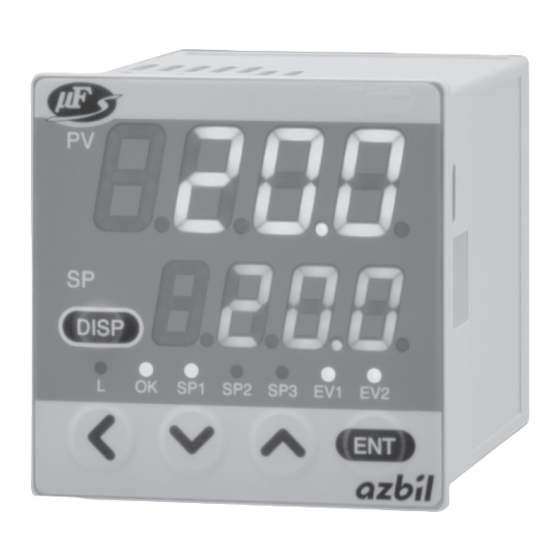
Chapter 2. NAMES AND FUNCTIONS OF PARTS „ „ Display Upper display: Displays the instantaneous flowrate value (7-segment display). When the display is switched, it also displays the integrated flowrate value (upper 4 digits), parameter setup item, function setup item or alarm details. Lower display: Displays the set flowrate (7-segment display). -
Page 15: Mounting And Wiring
Chapter 3. MOUNTING AND WIRING WARNING Never allow gases that are within explosive limits to pass through this controller. Doing so might result in explosion accidents. Do not use this controller for gases other than standard compatible gas types (Air/Nitrogen, argon and carbon dioxide (CO CAUTION Prevent foreign matter from entering the controller. -
Page 16: Mounting
Chapter 3. MOUNTING AND WIRING CAUTION Be sure to check that the wiring is correct before you turn the power ON. Incorrect wiring might cause damage or malfunction. If there is a risk of a power surge caused by lightning, use a surge absorber (surge protector) to prevent fire or device failure. - Page 17 Chapter 3. MOUNTING AND WIRING Joint connection „ • Connect the joint by holding the hexagonal section of the pipe connection port of the body with a spanner (or wrench). Handling Precautions • Do not hold the case of the controller with your hand when screwing the joint into the connection port.
- Page 18 Chapter 3. MOUNTING AND WIRING External dimensions „ unit : mm Connector (accessory) Mounting bracket (accessory) 44.8 Connection 12.7 Loader port OUT jack No.1 DISP 2-Rc1/8 Connection No.9 port IN 13.5 Applicable panel plate thickness is 2 to 7 mm Panel cutout „...
- Page 19 Chapter 3. MOUNTING AND WIRING Mounting on a panel „ The mounting panel should be used with a thickness of 2 to 7 mm of steel. Mounting bracket Panel cutout Mounting bracket screws Hook Panel Handling Precautions • To fasten this controller onto the panel, tighten a mounting bracket screws, and turn one more half turn when there is no play between the bracket and panel.
-
Page 20: Wiring
Chapter 3. MOUNTING AND WIRING „ „ Wiring CAUTION Be sure to turn the power supply source OFF before wiring connection. Doing so might cause faulty operation. The power supply circuit of this controller and the I/O circuit are not isolated each other. Therefore, ensure that the power supply of this controller is isolated from the power supply for external devices (insulate the power supply). - Page 21 Chapter 3. MOUNTING AND WIRING Wtiring example „ Internal circuit 24 V DC POWER (24 V) POWER GND Event output 1 Event output 2 (Output common) AI / DA Analog setting voltage input / DA AO / DB Analog flowrate voltage output / DB SIGNAL GND Analog input/output common / SG z Power supply...
- Page 22 Chapter 3. MOUNTING AND WIRING z Analog input/output (only for the model with analog I/O function) „ 0 to 5 V or Analog input 1 to 5 V input Analog output 0 to 5 V or 1 to 5 V output SIGNAL GND Handling Precautions •...
-
Page 23: Basic Operation
Chapter 4. BASIC OPERATION 4 - 1 Switching Displays Each press of the [DISP] key switches the display as shown below. The display shown below is an example. Power ON Instantaneous Multi-setting flowrate display flowrate display *4, *5 [DISP]key (1 s or more) Setting flowrate Instantaneous No. - Page 24 Chapter 4. BASIC OPERATION „ Operating mode display (+ instantaneous flowrate display) When the [DISP] key is pressed (for less than 1 second) while the instantaneous flowrate is displayed, the upper display maintains the instantaneous flowrate and the lower display indicates the operation mode. The table below shows the display contents to each operation mode.
-
Page 25: Setting The Flowrate
Chapter 4. BASIC OPERATION 4 - 2 Setting the Flowrate „ „ Procedure for changing flowrate in digital setting „ Single SP setting mode (number of SPs = 1 according to function setup C-04) Follow the procedure below to change the SP value (setting flowrate). (1) Press the [DISP] key. - Page 26 Chapter 4. BASIC OPERATION (5) Press the [ ] key or [v] key to change the SP value. >> The digit being changed blinks. You can move to the digit to be changed by pressing the [<] key. (6) When the target value is displayed, press the [ENT] key. >>...
-
Page 27: Procedure For Changing Flowrate In Analog Setting
Chapter 4. BASIC OPERATION „ „ Procedure for changing flowrate in analog setting (a model with analog input / output function) To change the SP value (setting flowrate value) using an external setting voltage, "1: Analog setting" is selected at the flowrate setup method selection C-03 in the function setup. -
Page 28: Selecting The Operating Mode
Chapter 4. BASIC OPERATION 4 - 3 Selecting the Operating Mode When the [DISP] key is pressed for less than 1 second while the instantaneous flowrate is displayed (same as the display at power supply ON), the instantaneous flowrate indication on the upper display is not changed, and the lower display shows the operating mode, enabling the selection of operation mode. -
Page 29: Advanced Operation
Chapter 5. ADVANCED OPERATION When the following operation is performed while the integrated flowrate is displayed, the parameter setup mode and function setup mode are entered, and each setting value can be changed: Power ON Multi-setting Instantaneous flowrate display flowrate display [DISP]key (1 s or more) Setting flowrate No. -
Page 30: Function Setup
Chapter 5. ADVANCED OPERATION 5 - 1 Function Setup Follow the procedure below to set the functions such as event output type and external switch input assignments: (1) Press the [DISP] key to display the integrated flowrate value. >> "L" lamp lights. (2) Keep the [ ] key pressed for 3 seconds or more. - Page 31 Chapter 5. ADVANCED OPERATION „ „ Function setup item list Factory Display Item Item Description Setup Item and Description Remarks Setting Key lock 0: Unlocked The key lock can be canceled even C-0 1 1: Settings other than flowrate setting while it is enabled.
- Page 32 Chapter 5. ADVANCED OPERATION Setup Item and Factory Display Item Item Description Remarks Description Setting External switch 0: Not used 3: To select an SP No. of 3 or more C- 10 input 1 function setting, assign "3" both the C- 10 1: Reset integration and C- 1 1 .
- Page 33 Chapter 5. ADVANCED OPERATION Setup Item and Factory Display Item Item Description Remarks Description Setting Inlet pressure 0: 0 to 0.1 MPa The accuracy drift caused by C-20 the influence of pressure can be adjustment 1: 0.05 to 0.15 MPa compensated by adjusting the inlet 2: 0.15 to 0.25 MPa pressure setting to the actual inlet...
-
Page 34: Parameter Setup
Chapter 5. ADVANCED OPERATION 5 - 2 Parameter Setup „ „ Setup method Follow the procedure below to set the parameters such as flowrate deviation alarm upper and lower limit flowrate and event output delay time. (1) Press the [DISP] key to display the integrated flowrate. >>... - Page 35 Chapter 5. ADVANCED OPERATION Parameter setup item list „ Factory Referential Display Description Setting Range Remarks Setting function setup Flowrate OK (2 % FS) (0.5 to 100 % FS) Unit: L / min(standard) 0.r G C-07, judgment range C-08 Flowrate OK (1 % FS) (0.5 to 100 % FS) 0.HyS...
- Page 36 Chapter 5. ADVANCED OPERATION *3 This item can be set only when other than "0: Not used" is selected at the flowrate alarm setup type C- 15 in the function setup. *4 This item can be set only when other than "0: Not used" is selected at the event output type assignment C-07 and C-08 in the function setup.
-
Page 37: Troubleshooting
Chapter 6. TROUBLESHOOTING „ „ Alarm code display When a flowrate deviation alarm occurs or when an alarm occurs during controller self-diagnostics, the operating mode currently selected at "Operation selection at alarm occurrence" C- 16 in the function setup is forcibly switched to. (Except AL7 1) The upper display alternately indicates the alarm codes shown in the table below and the regular display. -
Page 38: Other Troubles
Chapter 6. TROUBLESHOOTING „ „ Other troubles Error Cause Countermeasure Flowrate display does not become • Zero point shift due to the influence of • Adjust the inlet pressure setting zero even in spite of an actual zero pressure. (function setup C-20) with the actual flowrate. -
Page 39: Specifications
Chapter 7. SPECIFICATIONS „ „ Specifications Specifications are given on the next page. - Page 40 Chapter 7. SPECIFICATIONS Model No. MPC9500 MPC0002 Item Valve type Proportional solenoid valve Valve operation Normally closed when de-energized (N.C.) Standard full-scale flowrate 0.500 L/min(standard) 2.00 L/min(standard) (nitrogen conversionvalue) * Standard compatible gas types Air/Nitrogen, argon, carbon dioxide (CO Note; The gas must be a dry gas not containing corrosive components (chlorine, sulfur, acid).
- Page 41 Chapter 7. SPECIFICATIONS MPC0005 MPC0020 Proportional solenoid valve Normally closed when de-energized (N.C.) 5.00 L/min (standard) 20.0 L/min (standard) Air/Nitrogen, argon, carbon dioxide (CO Note; The gas must be a dry gas not containing corrosive components (chlorine, sulfur, acid). The gas must also be a clean gas not containing dust or oil mist. 2 to 100 % FS * Within 1.0 s (typ) to set point ±2 % FS ±2 % FS max.
- Page 42 Chapter 7. SPECIFICATIONS Model No. MPC9500 MPC0002 Item Flowrate Max. output voltage 7 V DC max. (maximum output when flowrate exceeds range) output Accuracy ±0.5 % FS (The input impedance of the connected device must be at least 100 kΩ.) Total output accuracy: Indication accuracy ±0.5 % FS...
- Page 43 Chapter 7. SPECIFICATIONS MPC0005 MPC0020 7 V DC max. (maximum output when flowrate exceeds range) ±0.5 % FS (The input impedance of the connected device must be at least 100 kΩ.) Total output accuracy: Indication accuracy ±0.5 % FS 2 points 30 V DC 15 mA max.
-
Page 44: Opened (In Air)
Chapter 7. SPECIFICATIONS „ „ Relationship between flowrate and differential pressure with valve fully opened (in air) MPC9500 MPC0002/0005 150 kPa(gauge) 150 kPa(gauge) 50 kPa(gauge) 50 kPa(gauge) 0 kPa(gauge) 0 kPa(gauge) -50 kPa(gauge) -50 kPa(gauge) Di rential pressure [kPa] Di rential pressure [kPa]... - Page 45 Revision History of CP-SP-1153E Date Rev. (New) Page No. Description Feb. 2004 Overall revision. 2nd ed = 2nd Jp ed. Mar. 2008 Company name changed. Apr. 2012 Apr. 2013 The title of this manual was changed. A CAUTION was changed. i, 1-1, 3-8 MPC Series →...
- Page 46 Warranty period and warranty scope 1.1 Warranty period Azbil Corporation’s products shall be warranted for one (1) year from the date of your purchase of the said products or the delivery of the said products to a place designated by you.
- Page 47 Although acceleration of the above situation varies depending on the conditions or environment of use of the products, you are required not to use any Azbil Corporation’s products for a period exceeding ten (10) years unless otherwise stated in specifications or instruction manuals.
- Page 48 Specifications are subject to change without notice. (11) 1-12-2 Kawana, Fujisawa Kanagawa 251-8522 Japan URL: https://www.azbil.com 1st edition: Feb. 2004 (W) 5th edition: Nov. 2019 (V)
Need help?
Do you have a question about the MPC0002 and is the answer not in the manual?
Questions and answers