Table of Contents
Advertisement
Quick Links
(Not for use in Japan)
No. CP-SP-1448E
Single Loop Controller
Model C1M
User's Manual
for Installation and Configuration
Thank you for purchasing your Azbil
Corporation product.
This manual contains information for
ensuring the safe and correct use of
the product.
Those designing or maintaining
equipment that uses this product
should first read and understand
this manual. This manual contains
information not only for installation,
but also for maintenance,
troubleshooting, etc. Be sure to keep it
nearby for handy reference.
Advertisement
Table of Contents

Related Manuals for Azbil C1M


Summary of Contents for Azbil C1M
- Page 1 (Not for use in Japan) No. CP-SP-1448E Single Loop Controller Model C1M User’s Manual for Installation and Configuration Thank you for purchasing your Azbil Corporation product. This manual contains information for ensuring the safe and correct use of the product. Those designing or maintaining...
- Page 2 Considerable effort has been made to ensure that this manual is complete and accurate, but if you should find an omission or error, please contact us. In no event is Azbil Corporation liable to anyone for any indirect, special, or consequential damages as a result of using this product.
- Page 3 Safety Requirements To reduce the risk of an electric shock resulting in personal injury, follow all safety notices in this document. This symbol warns the user of a potential shock hazard. Use of this product in a manner not specified by the manufacturer will impair its built-in safety features. Do not replace any component except as specified by the manufacturer.
-
Page 4: Conventions Used In This Manual
Conventions Used in This Manual „ The safety precautions explained below aim to prevent injury to you and others, and to prevent property damage. Warnings are indicated when mishandling this product may WARNING result in death or serious injury. Cautions are indicated when mishandling this product may CAUTION result in minor injury or property damage only. - Page 5 Numeric value and character display on LCD Numeric values: The 7-segment LCD expresses numeric values as follows: Alphabetical characters: The 7-segment LCD expresses alphabetical characters shown below. There are some alphabetical characters which are not displayed on the LED. - Handling Precautions: •...
-
Page 6: Safety Precautions
Safety Precautions WARNING To prevent electrical shock, this device must be installed in a location that is only accessible to people with appropriate knowledge about electrical safety. Install this device inside a control panel that cannot be opened without the use of a key or tool. Do not use this device in an environment with conductive contamination, or with dry non-conductive contamination which can become conductive due to condensation, etc. -
Page 7: Before Using This Device
CAUTION If there is a risk of a power surge caused by lightning, use a surge absorber (surge protector). Otherwise, there is a danger of fire or device failure. Do not operate the keys with a sharp object (such as a mechanical pencil tip, etc.). Doing so can cause device failure. -
Page 8: The Role Of This Manual
The Role of This Manual There are five different manuals related to model C1M Single Loop Controller (hereafter “this device”). Read them as necessary for your specific requirements. If you do not have a manual you require, please contact us or one of our dealers. -
Page 9: Organization Of This User's Manual
Displayed Items and Settings Displayed items and settings. Chapter 7. CPL Communication Function Communication with a host device (PC, PLC, etc.) using Azbil’s standard CPL communication and RS-485. Chapter 8. Modbus Communication Function Communication with a host device (PC, PLC, etc.) using Modbus communication and RS-485. -
Page 10: Table Of Contents
Safety Requirements Conventions Used in This Manual Safety Precautions Before Using This Device The Role of This Manual Organization of This User’s Manual Quick Reference Guide for Model C1M Flowchart of Key Operations and Displays Operation Examples Parameters Chapter 1. Overview... - Page 11 „ RS-485 communication connections „ Connecting solid state relays (SSR) „ Connecting the current output device 4-11 „ Noise suppression measures 4-11 4 - 2 Cables 4-12 Chapter 5. Functions 5 - 1 PV Input „ PV input range type „...
- Page 12 „ Specifying LSP group selection by DI assignment 5-34 „ SP ramp unit 5-35 „ SP up ramp / down ramp 5-36 „ SP low/high limit 5-37 „ Enabling/disabling SP ramp by DI assignment 5-37 5 - 6 Step operation 5-38 „...
- Page 13 „ Mode display setup 5-94 „ PV/SP display setup 5-95 „ MV display setup 5-96 „ Event display setup 5-97 „ Event remaining time display setup 5-97 „ CT input current display setup 5-98 „ User level 5-98 Status indicator 5-98 „...
- Page 14 „ Write data range 7-13 „ Write conditions 7-13 7 - 4 Definition of Word Addresses 7-13 7 - 5 Numerical Representation in the Application Layer 7-14 „ RS and WS commands 7-14 „ RD, WD, RU, and WU commands 7-14 7 - 6 List of Termination Codes...
- Page 15 „ Transfer settings 9-18 „ Data settings 9-18 Chapter 10. List of Communication Data 10-1 List of communication data 10-1 „ Chapter 11. Maintenance and Troubleshooting 11-1 „ Maintenance 11-1 „ Alarm codes and countermeasures 11-2 „ Operation when a PV input error occurs 11-4 Chapter 12.
-
Page 17: Quick Reference Guide For Model C1M
If more detailed information on model C1M is needed, refer to the user's manual for installation and configuration (CP-SP-1448E). The most convenient way to configure the C1M is with the Smart Loader Package (model No. SLP-C1FJA_). Please contact the azbil Group or a distributor for more information. -
Page 18: Flowchart Of Key Operations And Displays
Flowchart of Key Operations and Displays When the power is turned ON LSP1 ST. 0 HEAT COOL Step MV for MV for group heating cooling 0. 0 0 65. 3 65. 3 65. 3 Step remaining time Timer remaining UF-8 UF-7 UF-2 UF-1... - Page 19 Some items are not displayed depending on the availability of optional functions, model number, display setup ( C73 to C78 ) and user level ( C79 ). Pressing the [PARA] key while changing the setting of an item will cancel the change, and the next item will be displayed. Operation display Internal Internal...
-
Page 20: Operation Examples
Operation Examples : Initial setup procedure Red letters : Procedure during operation Blue letters Setup of PV input range type Execution of auto tuning (AT) AT forces ON/OFF of the MV a number of times (a limit cycle) to calculate Press [MODE] Hold down [PARA] PID values. - Page 21 For highlighted steps (e.g., ), the following precaution applies: • If keys are locked, the setting does not flash and cannot be changed. To change the setting, cancel the key lock first. RUN/READY mode selection Setup of event value Press [MODE] Hold down [PARA] Press [MODE] Hold down [PARA]...
-
Page 22: Parameters
Parameters : Essential parameters for PV measurement and control : Basic parameters : Required when using optional functions Operation settings Setup bank, etc., settings Setup bank Display Item Contents Initial Setting StUP Left: upper display value Right: lower display Display Item Contents Initial... - Page 23 Items marked with in the tables are displayed if standard configuration or advanced configuration is selected for the user level. To change the user level, see Changing the user level at the bottom right of this page. Event configuration bank Lock bank EvCF Display...
- Page 24 PV input range table Event types Thermocouple Direct action Reverse action Operation : ON/OFF changes at the value : ON/OFF changes at the value Setting C0 1 Sensor Range Range C0 1 Sensor Range Range type : ON/OFF changes when the value : ON/OFF changes when the value Setting type...
-
Page 25: Chapter 1. Overview
Chapter 1. Overview 1 - 1 Overview This is a compact controller (48 × 48 mm mask) with the features below. • LED display for excellent visibility • Easy setting by [MODE], [PARA], and digit-change keys on the front panel. •... -
Page 26: Model Selection Table
Chapter 1. Overview „ Model Selection Table Model selection of this device is shown below. Add'l proc. Basic model Control Installation Power Options Specifications output input Digits Basic model No. Screw terminal block Control output 1 Control output 2... -
Page 27: Accessories
Chapter 1. Overview „ Accessories Name Qty. Notes Mounting bracket 1 When replacing, use model 84515488-001. Gasket When replacing, use model 84515487-001. User’s manual Document No. CP-UM-5964JEC „ Optional parts Name Model No. Notes Mounting bracket 84515488-001 For maintenance (qty.: 1) Gasket 84515487-001 For maintenance (qty. -
Page 28: Model C1M And Its Console
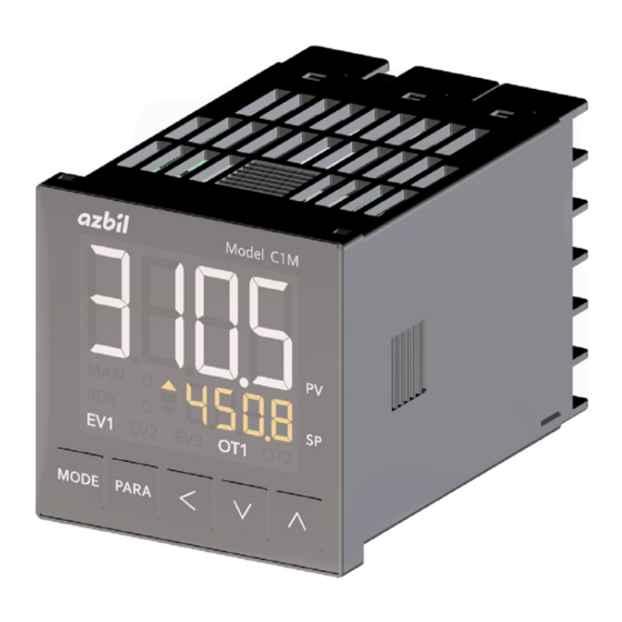
Chapter 1. Overview 1 - 2 Names and Functions of Parts „ Model C1M and its console Display Operation panel (14) (10) (11) (12) (13) (1) Upper display: Shows PV (present temperature, etc.) or items that can be set. (2) [MODE] key: Shows the operation display. -
Page 29: Terminals
Chapter 1. Overview „ Terminals Terminals Terminals: Used to connect the power, inputs, outputs, etc. M3 screws are used. For terminal connections, use crimp terminal lugs compatible with M3 screws. The tightening torque of the terminal screws is 0.6 ± 0.1 N·m. -
Page 31: Chapter 2. Outline Of Functions
Chapter 2. Outline of Functions 2 - 1 Input/Output Configuration Other Analog output PV Input Control outputs 1–2 processing Control processing processing (current output) (ON/OFF control, PID control) Internal contacts Digital inputs 1–2 processing Control outputs 1–2 (relay output, voltage pulse output) Internal event Digital processing... -
Page 32: Key Operation
Chapter 2. Outline of Functions 2 - 2 Key Operation Various displays and settings can be called up to the console using keys. There are two key operation modes, standard and special, which can be selected in the setup bank. Display transitions and use of keys in each mode are shown below. - Page 33 Chapter 2. Outline of Functions Display at power-on After power-on: all on all off sequential on and off operation display (sequence takes about 9 s) If no key press for 3 min If no key press for 3 min Press [MODE] 2-second press of 2-second press of...
-
Page 34: Special Mode
Chapter 2. Outline of Functions „ Special mode If C71 (key operation mode) in the setup bank is set to 1, the keys operate in special mode. In this mode, items that can be set are displayed in the order shown below. Operation settings Bank selection 5-95... - Page 35 Chapter 2. Outline of Functions Display at power-on Power-on all on all off sequential on and off operation display (sequence takes about 9 s) If no key press for 3 min If no key press for 3 min 2-second press of [PARA] Press [MODE]...
-
Page 36: How To Set Data
Chapter 2. Outline of Functions „ How to set data (1) Press [PARA] until the desired item is displayed. Display transitions and the use of [PARA] are described on pages 2-3 and 2-5. When configuring C01 (PV input When switching between RUN range type) in the setup bank and READY by the r--r parameter (2) Press [<], [∨], or [∧]. -
Page 37: Using The [Mode] Key
Chapter 2. Outline of Functions Handling Precautions • If a value does not flash after [<], [∨], or [∧] is pressed, the value cannot be changed. For example, if the RUN/READY selection is set in the DI assignment bank, the device keys cannot be used to switch between RUN and READY. •... -
Page 38: User Level
Chapter 2. Outline of Functions Handling Precautions • If C72 ([MODE] key function) in the setup bank is set to 0 (invalid), or if the specified switching operation is disabled, switching using [MODE] is not possible. • If you press [MODE] when the screen for specifying settings (parameters, setup items, etc.) is displayed, this device shows the operation display, but continuing to press [MODE] will not change the setting. - Page 39 Chapter 2. Outline of Functions 2 - 3 Operation Modes The transitions between operation modes are shown below. RUN + AUTO mode RUN/READY READY + AUTO mode AT stopped switching AT stopped AT running AUTO/MANUAL AUTO/MANUAL switching switching RUN + MANUAL mode RUN/READY READY + MANUAL mode switching...
-
Page 41: Chapter 3. Installation
Chapter 3. Installation WARNING To prevent electrical shock, this device must be installed in a location that is only accessible to people with appropriate knowledge about electrical safety. Install this device inside a control panel that cannot be opened without the use of a key or tool. Do not use this device in an environment with conductive contamination, or with dry non- conductive contamination which can become conductive due to condensation, etc. -
Page 42: Installation Location
Chapter 3. Installation „ Installation location Install this device as specified in Operating conditions (p. 14-5) and in a location that meets the following criteria: • Common mode voltage of all I/O except for the supply power and relay contact outputs: voltage to ground of 30 V max., 42.4 V peak max., and 60 V DC max. -
Page 43: External Dimensions
Chapter 3. Installation „ External dimensions Unit: mm Mounting bracket (included) Terminal screw „ Panel cutout dimensions For a panel-mounted model, open a hole in the panel as shown below. Unit: mm +0.5 30 min. (48×N−3) +0.5 (N: number of mounted units) Independent mounting Gang mounting Handling Precautions... -
Page 44: Mounting Method
Gasket (included)* * Used only for waterproof mounting Catch Model C1M Panel (1) Place the gasket on the terminal side of this device and slide it to the back of the console. (2) Insert this device from the front of the panel. - Page 45 (1) Mount the C1M in a panel as shown in the figure above. (2) Set the two protrusions on the top of the hard cover into the two dents on the top of the C1M. (3) Push the bottom of the hard cover onto the C1M until it clicks into place.
-
Page 47: Chapter 4. Wiring
Chapter 4. Wiring 4 - 1 Wiring WARNING To prevent electrical shock, this device must be installed in a location that is only accessible to people with appropriate knowledge about electrical safety. Install this device inside a control panel that cannot be opened without the use of a key or tool. Do not use this device in an environment with conductive contamination, or with dry non- conductive contamination which can become conductive due to condensation, etc. -
Page 48: Symbols Used In The Terminal Wiring Label
Chapter 4. Wiring „ Symbols used in the terminal wiring label The following table shows the meaning of the symbols used in the terminal wiring label on the side of the device. Symbol Description ∼ Caution: risk of electrical shock Caution „... - Page 49 Chapter 4. Wiring • Make sure that devices or equipment connected to this device have reinforced insulation suitable for the maximum voltages of this device’s power supply and input/output components. • Attach the cover after wiring work. Terminal cover...
- Page 50 Chapter 4. Wiring Wiring Control outputs (–) CT inputs (–) Event outputs (–) DI/Comm. (–) Power supply () PV inputs (–) • Control outputs (–) •...
-
Page 51: Connecting Open Collector Outputs To Digital Inputs
• If this device is installed where there is considerable vibration or shock, be sure to use round crimp terminal lugs to prevent wires from coming off the terminals. • Be careful not to allow crimp terminal lugs to touch adjacent terminals. „ Connecting open collector outputs to digital inputs Model C1M... -
Page 52: Cables
Chapter 4. Wiring „ RS-485 communication connections If the system includes 3-wire devices only Model C1M (slave station) − Master station Shielded cable − Model C1M (slave station) Shielded cable − Terminating resistor Important • Connect a terminating resistor (120 Ω, 1/2 W or more recommended) to both ends of the RS-485 transmission line. - Page 53 Chapter 4. Wiring If the system includes 5-wire devices only Model C1M (slave station) − Master station Shielded cable − − Model C1M (slave station) Shielded cable − Terminating resistor Important • Connect a terminating resistor (120 Ω, 1/2 W or more recommended) to both ends of the RS-485 transmission line.
-
Page 54: Connecting Solid State Relays (Ssr)
Constant-current SSR Check the following specifications of your SSR and the specification of the voltage pulse output of the C1M. • Input current (maximum): If it is below the maximum current allowed for the voltage pulse output, the SSRs can be connected in parallel. - Page 55 Voltage between terminals (three G3PA units) = Voltage when open − Internal resistance × Total drive current = 19 V DC ±15 % − 18 Ω ±0.5 % × 21 mA ≈ 16 to 21 V Connection diagram Model C1M − − − −...
- Page 56 SSR is within the specified range. Example: when connecting two SSRs Connection diagram External resistance Model C1M − When connecting n units of the SSR, the voltage between the terminals of the SSR can be calculated by the expression below: ((V ×...
-
Page 57: Connecting The Current Output Device
When the power of this device is turned off, its current input circuit is disconnected. When connecting a current output device to multiple C1M units whose power can be turned on and off individually, use the separately sold resistor (81401325) and specify a voltage input range. - Page 58 Chapter 4. Wiring 4 - 2 Cables For thermocouple input, connect the unshielded wires of the thermocouple to the PV input terminals. If a thermocouple with a terminal block is used, or if the wiring distance is long, use compensating lead wires for connection with the terminals of this device.
-
Page 59: Chapter 5. Functions
Chapter 5. Functions 5 - 1 PV Input The following is a functional block diagram for PV input. For thermocouple For RTD For DC voltage/current PV input range type PV input range type PV input range type (Setup bank: C01) (Setup bank: C01) (Setup bank: C01) Reference junction compensation... - Page 60 Chapter 5. Functions „ PV input range type For thermocouple and resistance temperature detector, the sensor type and the temperature range can be selected. For DC voltage and DC current, the signal type can be selected. Item (bank) Display Description Initial value User level PV input range type...
- Page 61 Chapter 5. Functions Sensor type Range (Fahrenheit)* C04 initial setting display* setting value* range −300 +2200 °F (Fixed) 2200 °F (Fixed) 1500 °F (Fixed) 1100 °F (Fixed) ✓ 0.0 to 700.0 °F 0–1 −300 +700 °F (Fixed) 1500 °F (Fixed) 1100 °F (Fixed)
- Page 62 Chapter 5. Functions PV input range table (RTD) Sensor type Range (Celsius)* C04 initial setting display* setting value* range Pt100 −200 +500 °C (Fixed) JPt100 −200 +500 °C (Fixed) Pt100 −200 +200 °C (Fixed) JPt100 −200 +200 °C (Fixed) ✓ Pt100 −100.0 +300.0...
-
Page 63: Temperature Unit
Chapter 5. Functions PV input range table (DC voltage/current) Sensor type Range* C04 initial setting display* setting value* range 0–1 V The scaling range is −1999 to ✓ 0–3 +9999. 1–5 V ✓ 0–3 0–5 V ✓ 0–3 ✓ 0–10 V 0–3 ✓... -
Page 64: Reference Junction Compensation (Cold Junction Compensation)
Chapter 5. Functions „ Reference junction compensation (cold junction compensation) If the PV input type is thermocouple, either one of the options below can be selected: • This device does reference junction compensation (cold junction compensation). • This device does not do reference junction compensation (cold junction compensation) because an external cold junction compensation device (ice bath, etc.) is used. -
Page 65: Pv Decimal Point Position
Chapter 5. Functions „ PV decimal point position If the PV input type is DC voltage/current, or if some thermocouple or RTD range types are selected, the decimal point position of the PV input can be specified. Item (bank) Display Description Initial value User level... -
Page 66: Pv Range Low/High Limit
Chapter 5. Functions „ PV range low/high limit If the PV input type is DC voltage/current, scaling of the PV input can be specified. Item (bank) Display Description Initial value User level PV range low limit C 05 If the PV input type is DC voltage/current: Simple, standard, (setup bank) -
Page 67: Pv Low Limit Alarm Threshold
Chapter 5. Functions „ PV low limit alarm threshold Item (bank) Display Description Initial value User level PV input failure (under range) 0: −10 % FS Simple, C 97 type standard, 1: −5 mV (valid only when C01 (PV input advanced (setup bank) range type) is set to 17 or 23.) -
Page 68: Pv Limiting And Pv Low/High Limit Alarm
Chapter 5. Functions „ PV limiting and PV low/high limit alarm The PV low and high limits are specified for each PV input range No. In principle, −10 % FS is the low limit and +110 % FS is the high limit of the PV. Operation when a PV input error occurs (p. 11-4) The PV is limited to falling within the range. -
Page 69: Auto/Manual Mode
Chapter 5. Functions 5 - 2 Mode The user can switch AUTO/MANUAL modes and RUN/READY modes, stop or start the AT (auto tuning), release all DO (digital output) latches, and turn on or off user-defined bit 1. „ AUTO/MANUAL mode AUTO and MANUAL modes can be switched. -
Page 70: At (Automatic Tuning) Stop/Start
Chapter 5. Functions „ AT (automatic tuning) stop/start AT can be started or stopped. Item (bank) Display Description Initial value User level AT (Auto-Tuning) stop/start At. O F(0): AT stop Simple, At. O F (mode bank) standard, At. O n(1): AT start advanced •... -
Page 71: Release All Do (Digital Output) Latches
Chapter 5. Functions „ Release all DO (digital output) latches Whether to release all DO (digital output) latches can be set. Item (bank) Display Description Initial value User level Release all DO (digital output) do. L t Lt. O n(0): Latch continue Simple, Lt. -
Page 72: On/Off Control
Chapter 5. Functions 5 - 3 Control Functional block diagrams for control (ON/OFF control, PID control, Ra-PID control, heating/cooling control, etc.) are shown below. „ ON/OFF control Control method: ON/OFF control (Parameter bank: CTRL = 0 must be set) SP (target value) Output at PV alarm (Setup bank: C16) ON/OFF control operation... -
Page 73: Pid Control, Ra-Pid Control, Heating/Cooling Control
Chapter 5. Functions „ PID control, Ra-PID control, heating/cooling control Control method: PID control (Parameter bank: CTRL = 1 must be set) Heat/cool control (Setup bank: C26) Heat/cool control is used Heat/cool control is not used Control action (direct/reverse) setting in the DI assignment bank (DI assignment bank: dI 1 . -
Page 74: Control Method
Chapter 5. Functions „ Control method There are two control methods. Item (bank) Display Description Initial value User level Control method CTRL 0: ON/OFF control 0 or 1 Simple, standard, (parameter bank) 1: PID control advanced • If relay (R0) is selected for control output by the model No., the initial value is 0. For other models, the initial value is 1. -
Page 75: Special Control Output
Chapter 5. Functions „ Special control output The control output when the PV is abnormal and when the device is in READY mode and can be specified. Item (bank) Display Description Initial value User level Output operation at PV alarm C 15 0: Continue the control calculation Advanced... -
Page 76: Initial Output Type (Mode) Of Pid Control
Chapter 5. Functions „ Initial output type (mode) of PID control Item (bank) Display Description Initial value User level Initial output type (mode) of 0: Automatic Advanced C 21 PID control 1: Not initialized (setup bank) 2: Initialize (if a new SP is set) •... -
Page 77: Initial Output Of Pid Control
Chapter 5. Functions „ Initial output of PID control Item (bank) Display Description Initial value User level Initial output of PID control −10.0 to +110.0 % 0.0 or 50.0 % Advanced C 22 (setup bank) • If CtrL (control method) is set to “1” (PID control), this item is displayed and the setting can be changed. -
Page 78: On/Off Control
Chapter 5. Functions „ ON/OFF control The settings related to ON/OFF control can be specified. Item (bank) Display Description Initial value User level ON/OFF control differential 0 to 9999 U Simple, DIFF standard, (parameter bank) advanced ON/OFF control operating point −1999 to +9999 U Advanced OFFs... -
Page 79: Pid Control
Chapter 5. Functions „ PID control The settings related to PID control can be specified. Item (bank) Display Description Initial value User level Proportional band 0.1 to 999.9 % 5.0 % Simple, standard, (PID bank) advanced Integration time 0 to 9999 U 120 s (PID bank) (0 = no integral operation) -
Page 80: Heating/Cooling Control
Chapter 5. Functions PID control operation initialization PID control operation is initialized when: • PID control starts after RUN + MANUAL modes are switched to RUN + AUTO modes • PID control starts after READY + AUTO modes are switched to RUN + AUTO modes •... - Page 81 Chapter 5. Functions Note Heating/cooling output If C26 (heat/cool control ) is set to 1 (use (individual PID)), the heating and cooling MVs shown in the figures below are output in accordance with the setting for “Heat/cool control dead zone. ” Dead zone 100.0 % 100.0 %...
-
Page 82: At (Automatic Tuning)
Chapter 5. Functions „ AT (automatic tuning) The following settings can be specified for AT. Item (bank) Display Description Initial value User level MV low limit at AT −10.0 to +110.0 % 0.0 % Simple, AT. O L standard, (parameter bank) advanced MV high limit at AT AT. - Page 83 Chapter 5. Functions The following graph illustrates the differences in control results using PID constants calculated with each AT type. AT type = 1 (immediate response) AT type = 0 (normal) AT type = 2 (stable) Time Di erence in PV change when SP is changed •...
-
Page 84: Ra-Pid
Chapter 5. Functions Handling Precautions • If C26 (heat/cool control) is set to 2 (use (shared PID), execute AT with settings that satisfy: 50.0 % < MV low limit at AT (At. O L) < MV high limit at AT (At. O H) •... -
Page 85: Sp Lag
Chapter 5. Functions „ SP lag The SP lag is a filter function to prevent sudden changes in the SP used in control operations when the SP changes. Use the setting below for SP lag. Item (bank) Display Description Initial value User level SP lag constant SP. -
Page 86: How To Start At
Chapter 5. Functions 5 - 4 AT (Automatic Tuning) Function Use the AT function if: • You want to set CtrL (control method) to 1 (PID control) and set PID constants automatically. • The rise of PV is slow or the overshoot is large. AT function is available if CtrL (control method) is set to 1 (PID control). - Page 87 Chapter 5. Functions Operation while AT is running During AT, PID constants are calculated using limit cycles. (1) A limit cycle operation is performed using the MV switching point specified by “Type of MV switching point at AT” During AT, two values are output repeatedly. One of the values is “MV low limit”...
- Page 88 Chapter 5. Functions Handling Precautions • Before starting AT, check that the PV input and the actuators (heater power, etc.) are ready for control. • If CtrL (control method) is set to 0 (ON/OFF control), AT cannot start. Change the control method setting to 1 (PID control). •...
- Page 89 Chapter 5. Functions • If the two values are close, the PV may not change even if the MV has changed during AT. In this case, AT may not end. If this happens, stop AT manually, reset the MV low and high limits, and then start AT again. •...
- Page 90 Chapter 5. Functions 5 - 5 The following is a functional block diagram for the SP. 5 - 6 Step operation (p. 5-38) (for step operation) LSP system group (Setup bank: C30) For one LSP group For two or more LSP groups LSP1 LSP group selection in DI assignment bank (SP bank: SP1)
-
Page 91: Specifying The Sp Using Operation Settings
Chapter 5. Functions „ Specifying the SP using operation settings The SP for the LSP group (LSP1 to 8) that is being used can be specified. During an SP ramp, the SP that is displayed will be different from the LSP group SP, but when the setting is being changed using the keys, the value specified for the LSP group will be displayed. -
Page 92: Lsp Group No
Chapter 5. Functions „ LSP group No. The LSP group to display can be selected. Item (bank) Display Description Initial value User level LSP No. The rightmost digit shows the number. Simple, standard, (operation settings) From 1 to the number set for “LSP system advanced group”... -
Page 93: Sp Ramp Unit
Chapter 5. Functions „ SP ramp unit The time unit of the SP ramp can be specified. Item (bank) Display Description Initial value User level SP ramp unit C 32 0: 0.1 U/s Advanced (setup bank) 1: 0.1 U/min 2: 0.1 U/h •... -
Page 94: Sp Up Ramp / Down Ramp
Chapter 5. Functions „ SP up ramp / down ramp SP up ramp and down ramp can be specified. Item (bank) Display Description Initial value User level SP up ramp 0.0 U : No ramp 0.0 U Advanced (parameter bank) 0.1 to 999.9 U SP down ramp 0.0 U... -
Page 95: Sp Low/High Limit
Chapter 5. Functions „ SP low/high limit The SP low/high limit can be set in order to limit the range of the SP. Item (bank) Display Description Initial value User level SP low limit C 07 (PV range low limit to PV range high limit) PV range low Standard, limit advanced... - Page 96 Chapter 5. Functions 5 - 6 Step operation Using up to eight SP groups, a step operation where the SP changes as shown in the figure below can be executed. Configure a step operation by specifying the LSP, ramp, and time of each step. The PID group No. to use in each step can also be set.
-
Page 97: Sp Ramp Type
DCP551/552). With the DCP, operation restarts at the point of time in the RAMP or SOAK that was in progress when the power failure occurred, and with the SP at that time. With the C1M, operation restarts from the beginning of the RAMP or SOAK that was in progress. -
Page 98: Sp Ramp Unit
Chapter 5. Functions „ SP ramp unit The unit of the ramp’s slope in a step operation can be specified. Item (bank) Display Description Initial value User level SP ramp unit C 32 0: 0.1 U/s Advanced (setup bank) 1: 0.1 U/min 2: 0.1 U/h •... -
Page 99: Step Time Unit
Chapter 5. Functions „ STEP time unit The time unit of a SOAK segment in a step operation can be specified. Item (bank) Display Description Initial value User level STEP time unit C 33 0: 0.1 s Advanced (setup bank) 1: 1 s (the operation display shows min. -
Page 100: Step Pv Start
Chapter 5. Functions „ STEP PV start Whether to start a step operation with the PV and the type of PV start when it is used can be specified. Item (bank) Display Description Initial value User level STEP PV start C 34 0: No Advanced... -
Page 101: Step Loop
Chapter 5. Functions PV at the start Slope of step 1 ramp SP (for LSP1) Time READY Step 1 Step 2 Step 3 Operation starts with the down-ramp in step 1 „ STEP loop The operation when a step operation ends (loop back, etc.) can be specified. Item (bank) Display Description... -
Page 102: Step Operation: Lsp, Pid Group No., Ramp, Soak Time
Chapter 5. Functions „ Step operation: LSP, PID group No., ramp, soak time How to change the SP during a step operation and PID group No. can be specified. Item (bank) Display Description Initial value User level LSP (step 1) SP-1 SP low limit (C07) to SP high limit (C08) Simple,... - Page 103 Chapter 5. Functions Item (bank) Display Description Initial value User level LSP (step 5) SP-5 Same as step 1 Simple, standard, (SP bank) advanced PID group No. (step 5) PID. 5 Standard, advanced (SP bank) Ramp (step 5) RMP. 5 (SP bank) Soak time (step 5) TIM.
-
Page 104: Internal Contacts: Operation Type
Chapter 5. Functions „ Internal contacts: operation type Among the internal contact operation types, the following are related to step operation. Note • 5 - 7 Digital Input (DI) / Internal Contacts (p. 5-47) (for functions of internal contacts) Item (bank) Display Description Initial value... -
Page 105: Operation Type
Chapter 5. Functions 5 - 7 Digital Input (DI) / Internal Contacts The following is a functional block diagram for digital input (DI) and internal contacts. When not using input bit functions When using input bit functions Input bit functions are disabled Input assignment (DI assignment bank: dI1. - Page 106 Chapter 5. Functions „ Operation type The operation by internal contacts can be specified. Item (bank) Display Description Initial value User level Internal contact 1 operation DI1. 1 0 to 20 Simple, type standard, See the table below for the functions that advanced (DI assignment bank) can be set by these settings.
- Page 107 Chapter 5. Functions The functions that can be assigned by dI settings and the operations are shown below. Settings Functions Operation when Operation when No function None None LSP group selection (0/+1) LSP number: +0 LSP number: +1 LSP group selection (0/+2) LSP number: +0 LSP number: +2 LSP group selection (0/+4)
- Page 108 Chapter 5. Functions „ Internal event No. assignment If the operation type is set to “timer stop/start, ” specify an internal event No. by this item. Item (bank) Display Description Initial value User level Internal contact 1 DI1. 9 0: All internal events Advanced Internal event No.
-
Page 109: Input Bit Functions
Chapter 5. Functions „ Input bit functions There are four types of input bit functions. With this item, the function to use can be selected or all functions can be disabled. Item (bank) Display Description Initial value User level Internal contact 1 input bit DI1. -
Page 110: Input Assignment
Chapter 5. Functions „ Input assignment The four inputs (A, B, C, D) used for input bit functions can be selected. Item (bank) Display Description Initial value User level Advanced Internal contact 1 input assignment A DI1. 3 0: Normally open (normally off = 0) (DI assignment bank) 1: Normally closed (normally on = 1) Internal contact 1 input assignment B... -
Page 111: Input Assignment Polarity
Chapter 5. Functions „ Input assignment polarity Whether to reverse the data assigned to the four inputs (A, B, C, D) used for input bit functions can be specified. Item (bank) Display Description Initial value User level Internal contact 1 polarity DI1. -
Page 112: Di Assignment By Smart Loader Package Model Slp-C1F
Chapter 5. Functions „ DI assignment by Smart Loader Package model SLP-C1F When specifying the settings in the DI assignment bank using Smart Loader Package model SLP-C1F, select [Edit] → [Input/Output port setup] from the input menu. This will display a screen for easy setup of the input bit function type, input assignment, input assignment polarity, and function result polarity. - Page 113 Chapter 5. Functions 5 - 8 Internal Events The result of internal event processing can be output as control outputs or event outputs via the digital output (DO) processing circuit. Chapter 2. Outline of Functions (p. 2-1) (for details) The following is a functional block diagram for internal events. Operation type (Event configuration bank, operation type E1.
-
Page 114: Operation
Chapter 5. Functions „ Operation The operation of internal events is shown below. Operation differs depending on the type of operation, direct/reverse setting, event main setting, event sub-setting, hysteresis settings, etc. Note • For the meaning of U (unit), see the terminology list in the Appendix. Operation type Setting Direct action... - Page 115 Chapter 5. Functions Operation type Setting Direct action Reverse action : ON/OFF changes at the value : ON/OFF changes at the value : ON/OFF changes when the value is exceeded : ON/OFF changes when the value is exceeded Deviation high and low limits (Final SP reference) Main setting Sub-setting...
- Page 116 Chapter 5. Functions Operation type Setting Direct action Reverse action Loop diagnosis 1 Turns on if the PV does not change according to the increase or decrease of the MV. Use this setting to detect a failure of the actuator, etc. z Settings •...
- Page 117 Chapter 5. Functions Operation type Setting Direct action Reverse action Loop diagnosis 2 Turns on when the PV does not change according to the increase or decrease of the MV. Use this setting to detect a failure of the actuator, etc. z Settings •...
- Page 118 Chapter 5. Functions Operation type Setting Direct action Reverse action Loop diagnosis 3 Turns on when the PV does not change according to the increase or decrease of the MV. Use this setting to detect a failure of the actuator, etc. z Settings •...
- Page 119 Chapter 5. Functions Operation type Setting Direct action Reverse action Alarm ON when an alarm (alarm code AL01 to AL96) OFF when an alarm (alarm code AL01 to AL96) occurs, OFF otherwise occurs, ON otherwise (status) READY ON in READY mode OFF in READY mode (status) OFF in RUN mode...
- Page 120 Chapter 5. Functions „ Operation type The operation type can be set for internal events. Item (bank) Display Description Initial value User level Internal event 1 configuration 1 E1. C 1 0: No event Simple, standard, 1: PV high limit Operation type advanced 2: PV low limit...
-
Page 121: Direct/Reverse, Standby, And Ready Mode Operation
Chapter 5. Functions „ Direct/reverse, standby, and READY mode operation Direct/reverse, standby, and READY mode operation that is associated with operation type can be set. Item (bank) Display Description Initial value User level Internal event 1 configuration 2 E1. C 2 “1st digit”... -
Page 122: Alarm Or, Special Off, Delay Time Unit
Chapter 5. Functions „ Alarm OR, special OFF, delay time unit Alarm OR, special OFF, and delay time unit associated with operation type can be set. Item (bank) Display Description Initial value User level Internal event 1 configuration 3 “1st digit” (2nd, etc.) means the first digit 0000 Advanced E1. -
Page 123: Main Setting, Sub-Setting,Hysteresis
Chapter 5. Functions „ Main setting, sub-setting,hysteresis The main setting, sub-setting, and hysteresis associated with operation type can be set. Item (bank) Display Description Initial value User level Internal event 1 main setting −1999 to +9999 Simple, standard, The number of decimal places in the PV (event bank) advanced changes according to the operation type. -
Page 124: On Delay Time, Off Delay Time
Chapter 5. Functions „ ON delay time, OFF delay time ON delay is a function that delays the timing at which the internal event status is changed from OFF to ON. OFF delay is a function that delays the timing at which the internal event status is changed from ON to OFF. - Page 125 Chapter 5. Functions Item (bank) Display Description Initial value User level Internal event 5 ON delay E5. O n 0.0 to 999.9 s 0.0 s Advanced time (when “delay time unit” = 0.1 s) or 0 s (event bank) 0 to 9999 s (when “delay time unit”...
- Page 126 Chapter 5. Functions 5 - 9 Digital Output (DO) The following is a functional block diagram for digital output (DO). MV1 processing: ON/OFF control output, time proportional output, heating time proportional output of heating/cooling control MV2 processing: Cooling time proportional output of heating/cooling control (Parameter bank: tP.
-
Page 127: Mv1/Mv2 Processing
Chapter 5. Functions „ MV1/MV2 processing The time proportional cycle and time proportional cycle mode for MV1 and MV2 can be specified. Item (bank) Display Description Initial value User level Time proportional cycle 1 5 to 120 s 10 or 2 s Simple, (for MV1) (when the output includes the relay... - Page 128 Chapter 5. Functions • The minimum ON/OFF time is the minimum time to maintain the output status after switching the output ON/OFF. Until this time elapses, the output status is maintained even if the time to switch ON/OFF comes. • If time proportional minimum ON/OFF time 1 = 0: If MV1 is connected to the relay control output or event output in the DO assignment bank, or if time proportional cycle 1 is 10 s or longer, 250 ms applies.
-
Page 129: Operation Type
Chapter 5. Functions „ Operation type The operation type of control outputs 1–2 and event outputs 1–3 can be specified in the DO assignment bank. Item (bank) Display Description Initial value User level Control output 1 operation type Ot1. 1 0: Default output Advanced (DO bank) -
Page 130: Output Assignment
Chapter 5. Functions „ Output assignment The four inputs (A, B, C, D) used for output bit functions can be selected. Item (bank) Display Description Initial value User level Advanced Control output 1 output assignment A Ot1. 2 0: Normally open (normally off = 0) 1: Normally closed (normally on = 1) (DO assignment bank) Control output 1 output assignment B... -
Page 131: Output Assignment Polarity
Chapter 5. Functions • If relay output or voltage pulse output is set as the control output by the model No. and if one of functions 1 to 4 is set for the operation type of control outputs 1–2 (ot1. 1 to ot2. 1 ), the output assignment A–D setting of control outputs 1–2 (ot1. -
Page 132: Function Result Polarity
Chapter 5. Functions „ Function result polarity Whether to reverse the results of output bit functions 1 to 4 can be specified. Item (bank) Display Description Initial value User level Control output 1 polarity 0: Direct Advanced OT1. 7 (DO assignment bank) 1: Reverse Control output 2 polarity OT2. -
Page 133: Do Assignment By Smart Loader Package Model Slp-C1F
Chapter 5. Functions • To release the latches, do any of the following operations: turn the power off and then back on, set “release all DO latches” (do. L t) to Lt. O F (latch release) using the keys or communication, or change the above latch setting in the DO assignment bank to 0 (do not latch). - Page 134 Chapter 5. Functions 5 - 10 Application Examples This section gives examples of applications that use the assignment function of this device. „ Applications using the assignment function This section gives examples of settings using Smart Loader Package model SLP-C1F. To use the assignment function, set the user level to “Advanced (High function)”...
- Page 135 Chapter 5. Functions (3) Select [DO Assignment] under [Option], right-click the operation type field of [EV1], and select [Input/Output port setup]. (4) On the [Input/Output port setup] screen, configure the settings as shown below. (A) Select [Function 1] to output the OR of two operations. (B) Select [Internal event 1 (setting = 1: PV high limit)] for output assignment A.
- Page 136 Chapter 5. Functions Example 2: Start operation by switching to RUN mode with an external switch, and stop operation by automatically switching to READY mode 30 minutes after the set point is reached. Temperature Set point 30 min Time Control ON Control OFF z Explanation Timer start condition: AND of the external switch (DI1) and the target temperature...
- Page 137 Chapter 5. Functions z Sample settings • Event Event Display Internal event 1 Internal event 2 Operation type E _ . C 1 32: Timer 4: Deviation high limit Direct/reverse ---- 0: Direct E _ . C 2 Standby E _ . C 2 ---- 0: No standby Event state in...
- Page 138 Chapter 5. Functions z Key points for configuration Timer start condition: AND of DI1 and the target temperature (internal event 2: deviation high limit) Condition for RUN/ READY mode switching: AND of DI (input A) and the timer (input B). However, because the mode will be READY when the internal contacts are ON, the function result is reversed at the final stage of the internal contact 2 processing.
- Page 139 Chapter 5. Functions DI assignment (internal contact 2): Input/output port setup AND of DI1 (input A) and Reversed at this point because the mode Contacts switching the the timer (input B) will be READY when internal contact 2 is ON. mode (RUN/READY) Example 3: Simple operation [MODE] key...
- Page 140 Chapter 5. Functions z Sample settings • Event Event Display Internal event 1 Internal event 2 Operation type E _ . C 1 9: Deviation high and low 32: Timer (status) limits (final SP reference) Direct/Reverse E _ . C 2 1: Reverse ---- Standby...
- Page 141 Chapter 5. Functions z Other C72 ([MODE] key function): 7 (user-defined bit 1 switching) SP up ramp and down ramp: any z Key points for configuration The internal event 1 is a substitute for the guaranteed soak. Therefore, set the hysteresis of event 1 to “9999” so that the event will not turn OFF even if the PV fluctuates after it is turned ON.
- Page 142 Chapter 5. Functions DI assignment (internal contact 2): Input/output port setup Guaranteed soak conditions (RAMP has ended and the SP is within the deviation of the nal SP) Timer remains ON when counting ends to prevent it from restarting Contacts starting the timer when the PV changes.
-
Page 143: Continuous Output
Chapter 5. Functions 5 - 11 Continuous output The following is a functional block diagram for continuous output. Output range type (Setup bank: Output type (Setup bank: Output scaling low/high limit (Setup bank: Continuous output (current output) „ Output range The output range can be set for the current output. - Page 144 Chapter 5. Functions „ Output type The type of current output can be set. Item (bank) Display Description Initial value User level Control output 1 type C 43 0: MV Simple, standard, (setup bank) 1: Heating MV (for heating/cooling control) advanced 2: Cooling MV (for heating/cooling control) 3: PV...
-
Page 145: Output Scaling Low/High Limit
Chapter 5. Functions „ Output scaling low/high limit Output scaling low and high limits can be set for the current output. Item (bank) Display Description Initial value User level Control output 1 scaling low limit C 44 −1999 to +9999 Simple, standard, (setup bank) -
Page 146: Mv Scaling Width
C1M operates as the master and another controller operates as a slave. Set the width of the RSP that changes in conjunction with the change in the MV (0−100 %) of the C1M as the MV scaling width. 5-88... - Page 147 Chapter 5. Functions 5 - 12 Current Transformer (CT) Input There are two types of current values input from the CT input terminals. • Current when output ON: Used for heater burnout/overcurrent events. It can be displayed as CT current. •...
-
Page 148: Ct Operation Type
Chapter 5. Functions „ CT operation type Different operations can be set for CT inputs 1 and 2. Item (bank) Display Description Initial value User level CT1 operation type 0: Heater burnout detection Simple, C 36 standard, (setup bank) 1: Current measurement advanced CT2 operation type C 39... -
Page 149: Number Of Ct Turns / Number Of Ct Power Wire Loops
For example, if the power wire passes through the hole of the CT twice as shown below, set 2. Note that, if 0 is set, 1 applies (same result as when 1 is set). → To relay, power supply, etc. Power wire To heater, etc. ← CT input Model C1M 5-91... - Page 150 Chapter 5. Functions Handling Precautions • Make sure that the current does not exceed the high limit of the CT input that can be displayed. Exceeding the high limit may cause malfunction. • If this device detects a current exceeding the high limit of the CT input that can be displayed, a CT input error alarm (AL11) will be generated.
-
Page 151: Key Operation Mode
Chapter 5. Functions 5 - 13 Display on the Console and Key Operation What is displayed on the console and the use of the keys can be customized. „ Key operation mode There are two key operation modes, standard and special, which can be selected by the setting below. -
Page 152: Mode Display Setup
Chapter 5. Functions „ Mode display setup Whether to display the mode settings in the mode bank can be selected. Item (bank) Display Description Initial value User level Mode display setup C 73 Whether to display the settings in the Standard, mode bank is determined by the sum of advanced... -
Page 153: Pv/Sp Display Setup
Chapter 5. Functions „ PV/SP display setup Whether to show PV- and SP-related settings on the operation display can be selected. Item (bank) Display Description Initial value User level PV/SP display setup C 74 Whether to show the following items on Standard, the operation display is determined by the advanced... -
Page 154: Mv Display Setup
Chapter 5. Functions „ MV display setup Whether to show MV-related settings on the operation display can be selected. Item (bank) Display Description Initial value User level MV display setup C 75 Whether to show the following items on Standard, the operation display is determined by the advanced (setup bank) -
Page 155: Event Display Setup
Chapter 5. Functions „ Event display setup Whether to show the main- and sub-settings of internal events 1–3 on the operation display can be selected. Item (bank) Display Description Initial value User level EV display setup C 76 0: Do not show internal event settings on Standard, the operation display advanced... -
Page 156: Ct Input Current Display Setup
Chapter 5. Functions „ CT input current display setup Whether to show the CT current on the operation display can be selected. Item (bank) Display Description Initial value User level CT input current display setup C 78 0: Do not show the CT current on the Standard, operation display advanced... -
Page 157: User-Defined Function
Chapter 5. Functions „ User-defined function Up to eight more settings selected from various settings can be displayed as user- defined functions 1–8 on the operation display. Item (bank) Display Description Initial value User level User function 1 UF-1 Displayed characters are defined for each item. The ---- Standard, following are special cases. - Page 158 Chapter 5. Functions Specifying user-defined functions This section gives examples of settings using Smart Loader Package model SLP-C1F. Up to eight user-defined functions (parameters) can be assigned to the [PARA] key. Set frequently used functions to make the operation of this device easier. In the example below, the main setting of event 1 is set for UF1.
- Page 159 Chapter 5. Functions (4) In [Item select], select [801: Event main setting](low limit). 5-101...
- Page 160 Chapter 5. Functions 2. If you find a parameter to set for a user-defined function during configuration In this case, use the procedure below. (1) Place the cursor on the parameter you want to register. (2) Click the [User Function Register] icon. >>...
-
Page 161: Key Lock, Communication Lock, Loader Lock
Chapter 5. Functions „ Key lock, communication lock, loader lock With various lock functions, changing the settings and communication can be prohibited. Item (bank) Display Description Initial value User level Key lock 0: All settings can be specified. Simple, standard, (lock bank) 1: Mode, event, operation display, SP, advanced... -
Page 162: Password
Chapter 5. Functions „ Password If a password is set (password lock), key-locked items whose settings cannot be changed using the keys will not be displayed. Item (bank) Display Description Initial value User level Password display PASS 0 to 15 Simple, standard, (lock bank) -
Page 163: Chapter 6. Displayed Items And Settings
Chapter 6. Displayed Items and Settings 6 - 1 Operation Settings Meaning of user level settings 0: Simple configuration, 1: Standard configuration, 2: Advanced configuration „ Operation settings Display Item Description Initial User Notes value level SP low limit (C07) to SP high limit (C08) Whether to display can be Upper display: (target value) - Page 164 Chapter 6. Displayed Items and Settings Display Item Description Initial User Notes value level Timer remaining Setting cannot be changed Whether to display can be time 1 selected by the timer remaining The rightmost digit shows % for ON delay time display setting (C77).
-
Page 165: Parameter Settings
Chapter 6. Displayed Items and Settings 6 - 2 Parameter Settings Meaning of user level settings 0: Simple configuration, 1: Standard configuration, 2: Advanced configuration „ Mode bank Bank selection: MODE Display Item Description Initial User Notes value level AUTO/MANUAL AUTO Displayed if the control method AUtO: AUTO mode... -
Page 166: Sp Bank
Chapter 6. Displayed Items and Settings „ SP bank Bank selection: SP Display Item Description Initial User Notes value level SP (for LSP1) SP low limit (C07) to SP high limit (C08) SP-1 PID group No. 1 to 8 Displayed for PID control (CtrL PID. - Page 167 Chapter 6. Displayed Items and Settings Display Item Description Initial User Notes value level SP (for LSP5) Same as LSP group 1 Displayed if LSP system group SP-5 (C30) is set to 5 or more and the conditions for LSP1 described PID group No.
-
Page 168: Event Bank
Chapter 6. Displayed Items and Settings „ Event bank Bank selection: EV Display Item Description Initial User Notes value level Internal event 1 −1999 to +9999 The settings required for the main setting internal event 1 operation type The number of decimal places changes (E1. - Page 169 Chapter 6. Displayed Items and Settings Display Item Description Initial User Notes value level Internal event 4 Same as internal event 1 The settings required for the main setting internal event 4 operation type (E4. C 1) are displayed. Internal event 4 E4.
- Page 170 Chapter 6. Displayed Items and Settings „ PID bank Bank selection: PID Display Item Description Initial User Notes value level Proportional band 0.1 to 999.9 % Displayed if the control method (PID group 1) is PID control (CtrL = 1). Integration time 0 to 9999 (0 = no integral operation) (PID group 1)
- Page 171 Chapter 6. Displayed Items and Settings Display Item Description Initial User Notes value level Proportional band Same as PID group 1 Same as PID group 1 (PID group 2) Integration time (PID group 2) Derivative time (PID group 2) Manual reset 50.0 RE-2 (PID group 2)
- Page 172 Chapter 6. Displayed Items and Settings Display Item Description Initial User Notes value level Proportional band Same as PID group 1 Same as PID group 1 (PID group 3) Integration time (PID group 3) Derivative time (PID group 3) Manual reset 50.0 RE-3 (PID group 3)
- Page 173 Chapter 6. Displayed Items and Settings Display Item Description Initial User Notes value level Proportional band Same as PID group 1 Same as PID group 1 (PID group 4) Integration time (PID group 4) Derivative time (PID group 4) Manual reset 50.0 RE-4 (PID group 4)
- Page 174 Chapter 6. Displayed Items and Settings Display Item Description Initial User Notes value level Proportional band Same as PID group 1 Same as PID group 1 (PID group 5) Integration time (PID group 5) Derivative time (PID group 5) Manual reset 50.0 RE-5 (PID group 5)
- Page 175 Chapter 6. Displayed Items and Settings Display Item Description Initial User Notes value level Proportional band Same as PID group 1 Same as PID group 1 (PID group 6) Integration time (PID group 6) Derivative time (PID group 6) Manual reset 50.0 RE-6 (PID group 6)
- Page 176 Chapter 6. Displayed Items and Settings Display Item Description Initial User Notes value level Proportional band Same as PID group 1 Same as PID group 1 (PID group 7) Integration time (PID group 7) Derivative time (PID group 7) Manual reset 50.0 RE-7 (PID group 7)
- Page 177 Chapter 6. Displayed Items and Settings Display Item Description Initial User Notes value level Proportional band Same as PID group 1 Same as PID group 1 (PID group 8) Integration time (PID group 8) Derivative time (PID group 8) Manual reset 50.0 RE-8 (PID group 8)
-
Page 178: Parameter Bank
Chapter 6. Displayed Items and Settings „ Parameter bank Bank selection: PARA Display Item Description Initial User Notes value level Control method 0: ON/OFF control 0 or 1 The initial value is 0 if control CTRL 1: PID control output 1 is a relay output, and 1 otherwise. - Page 179 Chapter 6. Displayed Items and Settings Display Item Description Initial User Notes value level Time proportional 5 to 120 s 10 or 2 Displayed if heating/cooling cycle 2 (when the output includes a relay output) control is used (C26 ≠ 0) and MV2 (time proportional output 1 to 120 s for cooling in heating/cooling...
-
Page 180: Extended Tuning Bank
Chapter 6. Displayed Items and Settings „ Extended tuning bank Bank selection: ET Display Item Description Initial User Notes value level AT type 0: Normal (regular control characteristics) Displayed if the control method AT. T Y 1: Immediate response (to disturbance) is PID control (CtrL = 1). -
Page 181: Setup Bank
Chapter 6. Displayed Items and Settings 6 - 3 Setup Bank, etc., Settings Meaning of user level settings 0: Simple configuration, 1: Standard configuration, 2: Advanced configuration „ Setup bank Bank selection: STUP Display Item Description Initial User Notes value level PV input range type For thermocouple:... - Page 182 Chapter 6. Displayed Items and Settings Display Item Description Initial User Notes value level Output at READY −10.0 to +110.0 % Displayed if the control method C 18 (Cool) is PID control (CtrL = 1) and heating/cooling control is used (C26 ≠...
- Page 183 Chapter 6. Displayed Items and Settings Display Item Description Initial User Notes value level STEP time unit 0: 0.1 s C 33 1: 1 s (displayed as min.s on the console) 2: 1 min (displayed as h.min on the console) STEP PV start 0: No C 34...
- Page 184 Chapter 6. Displayed Items and Settings Display Item Description Initial User Notes value level Control output 1 0 to 9999 Displayed if control output 1 C 46 MV scaling width is set to current output by the The decimal point position and unit are model No.
- Page 185 Chapter 6. Displayed Items and Settings Display Item Description Initial User Notes value level [MODE] key function 0: Invalid C 72 1: AUTO/MANUAL mode selection 2: RUN/READY mode selection 3: AT stop/start 4: LSP group selection 5: Release all DO latches 6: Invalid 7: User-defined bit 1 8: Invalid...
- Page 186 Chapter 6. Displayed Items and Settings Display Item Description Initial User Notes value level Event remaining 0: Do not show the ON/OFF delay C 77 time display setup remaining time of internal events on the operation display 1: Show the ON/OFF delay remaining time of internal event 1 on the operation display 2: Show the ON/OFF delay remaining...
-
Page 187: Event Configuration Bank
Chapter 6. Displayed Items and Settings „ Event configuration bank Bank selection: EVCF Display Item Description Initial User Notes value level Internal event 1 0: No event E1. C 1 conf. 1 operation 1: PV high limit type 2: PV low limit 3: PV high and low limits 4: Deviation high limit 5: Deviation low limit... - Page 188 Chapter 6. Displayed Items and Settings Display Item Description Initial User Notes value level Internal event 1 “1st digit” (2nd, etc.) means the first digit E1. C 3 conf. 3 (etc.) from the right. 1st digit: Alarm OR 0: None 1: Alarm direct + OR operation 2: Alarm direct + AND operation 3: Alarm reverse + OR operation...
- Page 189 Chapter 6. Displayed Items and Settings Display Item Description Initial User Notes value level Internal event 4 Same as internal event 1 configuration 1 E4. C 1 conf. 1 operation type Internal event 4 Same as internal event 1 configuration 2 0000 E4.
-
Page 190: Di Assignment Bank
Chapter 6. Displayed Items and Settings „ DI assignment bank Bank selection: DI Display Item Description Initial User Notes value level Internal contact 1 0: No function DI1. 1 operation type 1: LSP group selection (0/+1) 2: LSP group selection (0/+2) 3: LSP group selection (0/+4) 4: PID group selection (0/+1) 5: PID group selection (0/+2) - Page 191 Chapter 6. Displayed Items and Settings Display Item Description Initial User Notes value level Internal contact 1 0: Normally open (normally off = 0) Displayed if internal contact 1 DI1. 3 input assignment A 1: Normally closed (normally on = 1) input bit function is set to one of functions 1–4 (DI1.
- Page 192 Chapter 6. Displayed Items and Settings Display Item Description Initial User Notes value level Internal contact 2 Same as internal contact 1 input Displayed if internal contact 2 DI2. 3 input assignment A assignment A to D input bit function is set to one of functions 1–4 (dI2.
- Page 193 Chapter 6. Displayed Items and Settings Display Item Description Initial User Notes value level Internal contact 3 Same as internal contact 1 input Displayed if internal contact 3 DI3. 3 . input assignment A assignment A to D input bit function is set to one of functions 1–4 (dI3.
- Page 194 Chapter 6. Displayed Items and Settings Display Item Description Initial User Notes value level Internal contact 4 Same as internal contact 1 input Displayed if internal contact 4 DI4. 3 input assignment A assignment A to D input bit function is set to one of functions 1–4 (dI2.
- Page 195 Chapter 6. Displayed Items and Settings Display Item Description Initial User Notes value level Internal contact 5 Same as internal contact 1 input Displayed if internal contact 5 DI5. 3 input assignment A assignment A to D input bit function is set to one of functions 1–4 (dI2.
-
Page 196: Do Assignment Bank
Chapter 6. Displayed Items and Settings „ DO assignment bank Bank selection: DO Display Item Description Initial User Notes value level Control output 1 0: Default output Displayed if control output 1 is Ot1. 1 operation type 1: MV ON/OFF status 1 (ON/OFF control set to relay output or voltage output, time proportional output, pulse output by the model No. - Page 197 Chapter 6. Displayed Items and Settings Display Item Description Initial User Notes value level Control output 1 “1st digit” (2nd, etc.) means the first digit Displayed if relay output or Ot1. 6 polarity A to D (etc.) from the right. voltage pulse output is set as control output 1 by the model 1st digit: Polarity A...
- Page 198 Chapter 6. Displayed Items and Settings Display Item Description Initial User Notes value level Event output 1 Same as control output 1 output Displayed if event output 1 is Ev1. 2 output assignment A assignment A to D selected by the model No. and event output 1 operation type 0 to 49 Event output 1...
- Page 199 Chapter 6. Displayed Items and Settings Display Item Description Initial User Notes value level Event output 3 Same as control output 1 operation type Displayed if a model with event Ev3. 1 operation type output 3 is used. 0: Default output 1: MV1 For event output 3, the default 2: MV2...
-
Page 200: User Function Bank
Chapter 6. Displayed Items and Settings „ User function bank Bank selection: UF Display Item Description Initial User Notes value level User function 1 Displayed characters are defined for - - - - Only the settings that can be UF-1 each item. -
Page 201: Lock Bank
Chapter 6. Displayed Items and Settings „ Lock bank Bank selection: LOC Display Item Description Initial User Notes value level Key lock 0: All settings can be specified. The setting can be specified if 1: Mode, event, operation display, SP, the two sets of passwords (1A UF, lock, manual MV, and [MODE] key and 1B, 2A and 2B) match. -
Page 202: Instrument Information Bank
Chapter 6. Displayed Items and Settings „ Instrument information bank Bank selection: i d Display Item Description Initial User Notes value level ROM ID − ROM firmware identification Always 16 id01 Setting cannot be changed ROM version 1 − id02 ROM version 2 −... - Page 203 Chapter 6. Displayed Items and Settings Display Item Description Initial User Notes value level Advanced function 0000 to FFFF (hex) 0000 FP10 password 10 Advanced function 0000 to FFFF (hex) 0000 FP11 password 11 Advanced function 0000 to FFFF (hex) 0000 FP12 password 12...
-
Page 205: Chapter 7. Cpl Communication Function
Features The features of the C1M’s communication functions are as follows: • Up to 31 C1M units can be connected to a single master station (host device). • Almost all of the parameter data of this device can be communicated. -
Page 206: Communication Procedure
„ Communication procedure The communication procedure is as follows. (1) The host device (master station) sends an instruction message to one C1M unit (slave station). (2) The slave station receives the instruction message and performs read or write processing according to the content of the message. -
Page 207: Message Structure
Chapter 7. CPL Communication Function 7 - 2 Message Structure „ Message structure The following shows the message structure. Messages are broadly classified into two layers: the data link layer and the application layer. • Data link layer This layer contains the basic information required for communications such as the destination of the communication message and the check information of the message. - Page 208 Chapter 7. CPL Communication Function List of data link layer data definitions The following list shows the definitions for data in the data link layer. Data name Character code Number of Meaning of data characters 02 h Start of message Station address 0 to 7FH are expressed as Identification...
- Page 209 Chapter 7. CPL Communication Function • ETX ETX indicates the end of the application layer. • Checksum This value is for checking whether something abnormal (e.g., electromagnetic noise) has caused the message content to change during transmission. The checksum is expressed as a 2-digit hexadecimal character code. •...
- Page 210 Chapter 7. CPL Communication Function „ Application layer The table below shows the configuration of the application layer. Item Description Command RS (read decimal format data from consecutive addresses) WS (write decimal format data to consecutive addresses) RD (read hexadecimal format data from consecutive addresses) WD (write hexadecimal format data to consecutive addresses) RU (read hexadecimal format data from random addresses) WU (write hexadecimal format data to random addresses)
-
Page 211: Description Of Commands
Chapter 7. CPL Communication Function 7 - 3 Description of Commands „ Continuous data read command (RS command) This command reads data from consecutive addresses in one message. Instruction message This is a command—in one message—to read data from consecutive word addresses starting from the specified address. -
Page 212: Continuous Data Write Command (Ws Command)
Chapter 7. CPL Communication Function „ Continuous data write command (WS command) This command writes data to consecutive addresses. Instruction message The figure below shows the structure of the application layer of a “write” instruction message. (2) (4) (2) (1) Write command (2) Data delimiter (3) Starting word address (4) Write data (1st word) -
Page 213: Fixed-Length Continuous Data Read Command (Rd Command)
Chapter 7. CPL Communication Function „ Fixed-length continuous data read command (RD command) This command reads continuous data in two-byte units. This command is suitable for handling data in ladder programs sent by PLC communications as the data is of a fixed length. -
Page 214: Fixed-Length Continuous Data Write Command (Wd Command)
Chapter 7. CPL Communication Function „ Fixed-length continuous data write command (WD command) This command writes continuous data in two-byte units. This command is suitable for handling data in ladder programs sent by PLC communications as the data is of a fixed length. -
Page 215: Fixed-Length Random Data Read Command (Ru Command)
Chapter 7. CPL Communication Function „ Fixed-length random data read command (RU command) This command reads random (non-consecutive) data in two-byte units. Instruction message The word address (four hexadecimal digits) of the data to be read is sent in the specified order. -
Page 216: Fixed-Length Random Data Write Command (Wu Command)
Chapter 7. CPL Communication Function „ Fixed-length random data write command (WU command) This command writes data to random (non-consecutive) addresses in two-byte units. Data is expressed in four hexadecimal digits. Instruction message Data is sent for the specified write data count with the data address (four hexadecimal digits) of the data to be written and the data (four hexadecimal digits) as a pair. -
Page 217: Ram And Eeprom Areas Of Data Addresses
Chapter 7. CPL Communication Function 7 - 4 Definition of Word Addresses „ RAM and EEPROM areas of data addresses Word addresses are categorized as follows: Word address Name Notes (Hexadecimal) 273W to 14859W RAM access word Reading and writing of these addresses address are both performed on RAM. -
Page 218: Numerical Representation In The Application Layer
Chapter 7. CPL Communication Function 7 - 5 Numerical Representation in the Application Layer The specifications of numerical representation are decimal variable-length (zero suppress) for RS and WS commands and hexadecimal fixed-length for RD, WD, RU and WU commands. Details are as follows: „... -
Page 219: List Of Termination Codes
Chapter 7. CPL Communication Function 7 - 6 List of Termination Codes If an error occurred in the application layer, a termination code indicating error is returned in a response message. Termination Description Process Example code Normal termination All the processing has completed successfully. - Page 220 Chapter 7. CPL Communication Function Termination Description Process Example code Any of the following alarms has occurred: Only the termination code is returned. The message is not • AL74: Nonvolatile memory error processed. • AL80: Nonvolatile memory not initialized • AL81: Setting value area error •...
-
Page 221: Reception And Transmission Timing
Chapter 7. CPL Communication Function 7 - 7 Reception and Transmission Timing „ Time specifications for instruction and response messages The cautions below are required with regard to the timing of command message transmission from the master station and response message transmission from the slave station (this device). -
Page 222: Precautions For Creating Communication Programs For The Master Station
The sample program is for your reference only, and there is no guarantee that all functions will work properly. Handling Precautions: • Azbil Corporation will not be liable for any loss or damage caused by applying this sample program. Before executing the sample program Check the settings for communication type, station address, transmission speed and data format of the instrument. - Page 223 Chapter 7. CPL Communication Function Compiling The following is an example of compiling with Visual Studio 2019. After launching x86 Native Tools Command Prompt for VS 2019 from the start menu, compile using the cl command. Example of execution results C:\Sample>cl cpl.cpp Microsoft(R) C/C++ Optimizing Compiler Version 19.29.30133 for x86 Copyright (C) Microsoft Corporation.
-
Page 225: Modbus Communication Function
Features Key features of the C1M’s communication functions are as follows: • Up to 31 C1M units can be connected to a single master station (host device). • Almost all of the parameter data of this device can be communicated. -
Page 226: Communication Procedure
„ Communication procedure The communication procedure is as follows. (1) The host device (master station) sends an instruction message to one C1M unit (slave station). (2) The slave station receives the instruction message and performs read or write processing according to the content of the message. -
Page 227: Message Structure
Chapter 8. Modbus Communication Function 8 - 2 Message Structure „ Message Structure The following shows the message structure. All messages are expressed in hexadecimal. Modbus/ASCII All messages are written in hexadecimal ASCII codes (each slot below represents one character). A MODBUS/ASCII message consists of (1) to (5) below. - Page 228 Chapter 8. Modbus Communication Function • Checksum (LRC) This value is for checking whether something abnormal (e.g., electromagnetic noise) has caused the message content to change during transmission. The checksum is expressed as a 2-digit hexadecimal character code. The procedure for calculating the checksum is as follows.
- Page 229 Chapter 8. Modbus Communication Function Modbus/RTU All messages use binary data (each slot below represents one byte). A Modbus RTU message consists of (1) to (3) below. The command (details sent from the master station) and the response (details returned from the slave station) are stored in (2). 1 frame (1) Station address (1 byte) (2) Instruction message, response message...
- Page 230 Chapter 8. Modbus Communication Function • Checksum (CRC) This value is for checking whether something abnormal (e.g., electromagnetic noise) has caused the message content to change during transmission. The check sum is expressed in two bytes. The procedure for calculating the checksum (CRC) is as follows. /* CRC calculation */ /* Input unsigned char length: Number of bytes sent */...
-
Page 231: Command Types
Chapter 8. Modbus Communication Function „ Command types Command (send message) types supported by this device are as follows. Command type Description Conformance class ASCII Read multiple data records 03 (2 bytes) 03H (1 byte) Write multiple data records 10 (2 bytes) 10H (1 byte) Write 1 data record 06 (2 bytes) - Page 232 Chapter 8. Modbus Communication Function „ Other specifications If there is an error in a response message, one of the exception codes shown below is added after the function code. Error type Exception code Description ASCII Illegal function code 01 (2 bytes) 01H (1 byte) Function code not supported by this device...
- Page 233 Chapter 8. Modbus Communication Function 8 - 3 Description of Commands „ Read command (03H) Instruction message This is a command—in one message—to read data from consecutive word addresses starting from the specified address. The following is a sample “read” instruction message.
- Page 234 Chapter 8. Modbus Communication Function • Abnormal termination 3AH 30H 41H 38H 34H 30H 31H 37H 31H 0DH 0AH CR LF (1) Start of the message (2) Station address (3) Error flag (Since undefined “04” was sent as a command with an instruction message, the most significant bit was turned ON and “84”...
- Page 235 Chapter 8. Modbus Communication Function „ Write command (10H) Instruction message This is a command—in one message—to write data to consecutive word addresses starting from the specified address. The following is a sample “write” instruction message. Example: 01A0H and 0E53H are written to two consecutive word addresses starting from 1501W (05DDH).
- Page 236 Chapter 8. Modbus Communication Function Modbus/RTU 01H 10H 05H DDH 00H 02 h D1H 3EH (1) (2) (1) Station address (2) Write command (10H) (3) Write starting word address (4) Write data count (5) Checksum (CRC) Note • The format of a response message for abnormal termination is the same as that of the read command.
-
Page 237: One Data Record Write Command (06H)
Chapter 8. Modbus Communication Function „ One data record write command (06H) Instruction message This is a command to write one data record to the specified address. The following is a sample write instruction message. Example: 01A0H is written to word address 1501W (05DDH). Modbus/ASCII 3AH 30H 31H 30H 36H 30H 35H 44H 44H 30H 31H 41H 30H 37H 36H 0DH 0AH CR LF... -
Page 238: Definition Of Word Addresses
Chapter 8. Modbus Communication Function 8 - 4 Specifications Common with CPL Communication Function „ Definition of word addresses 7 - 4 Definition of Word Addresses (p. 7-13) „ Numerical representation The specifications of numerical representation are the same as the following: 7 - 5 Numerical Representation in the Application Layer RD, WD, RU, and WU commands (p. 7-14) „... -
Page 239: Plc Link Communication Function
• Number of connected PLC units = 1 • Number of connected C1M units = 31 • Supported protocols: 3 types (Mitsubishi QnA-compatible 3C format 4, Omron FINS, Modbus/RTU) • Communication data count: 64 (PLC → C1M), 64 (C1M → PLC) -
Page 240: Precautions For The Plc Link Communication Function
• When the PLC link communication function is used, RS-485 communication with the host device cannot be used. • Do not connect anything other than the C1M and one PLC unit to the RS-485 communication line. • Set the C1M addresses from 1 to the maximum number of connected C1M units. - Page 241 (4) When transfer of the data specified for the sheet is complete, a completion notification is written. Handling Precautions • The normal memory area and RAM area are available for the data written from the PLC to the C1M. Chapter 10. List of Communication Data (for details)
- Page 242 Changing the controller settings (SP, PID, etc.) from the PLC • Changing the controller operations (RUN/READY mode selection, etc.) from the PLC The controller executes triggered data transfer as follows. Model C1M (1) Trigger = ON Trigger device M0000 (2) Read...
- Page 243 If the trigger device is turned off by the trigger device initialization function, its status is the same as when the C1M confirms that the trigger device is off. Therefore if the trigger device is turned on, it is detected in the next trigger device scan.
-
Page 244: Connectible Plcs
„ Usable devices The address ranges of the devices (data) usable with each model are as follows. C1M controller (this device) Various monitoring data and parameters can be selected in the PLC link settings in the SLP-C1F Smart Loader Package. - Page 245 Chapter 9. PLC Link Communication Function Omron Device type Address range Channel I/O bit 0000.00 6143.15 Internal auxiliary relay bit W0000.00 W0511.15 Retaining relay bit H0000.00 H1535.15 Special auxiliary relay bit A0000.00 A1471.15 Timer (up flag) T00000 T04095 Counter (up flag) C00000 C04095 Channel I/O...
- Page 246 Chapter 9. PLC Link Communication Function Modbus/RTU Device type Address range Coil 000001 065536 Input relay 100001 165536 Input register 300001 365536 Retaining register 400001 465536 Change the Modbus address used by the SLP in accordance with the address expression used for the connected Modbus device. The address expression in the Modbus protocol and the SLP is as follows.
-
Page 247: Completion Notification Data
Type Code Description Communication succeeded Normal response Timeout Timeout occurred in communication between the PLC and the C1M C1M error An error occurred with the C1M. PLC error An abnormal code is included in the reply data from the PLC. -
Page 248: Common Settings
Chapter 9. PLC Link Communication Function 9 - 3 PLC Link Setup To set up PLC link communication, use the SLP-C1F Smart Loader Package. Open the setup screen of the SLP-C1F and click the [PLC Link] button to open the [PLC Link] window. The method of setup is described below, illustrated by the SLP-C1F screen. - Page 249 1 to transfer 4 combined. [Remaining items] is displayed at the bottom of the screen. (6) Other lines can be selected by using [Up] and [Down]. (7) Set [PLC address] and [C1M address] by dragging and dropping an address in section [C]. Section [C] Address list (8) Select a device (PLC or C1M).
- Page 250 Transfer setting examples Cyclic data transfer (PLC → C1M) Used for writing parameters from the PLC to the C1M consecutively. In this example, data at D0000100 to D0000103 are transferred to the C1M periodically. z Transfer operation settings Transfer type: Cyclic transfer (PLC→C1M)
- Page 251 Transfer data settings D000100 → SP (target value) D000101 → P (Proportional Band) D000102 → I (Integral time) D000103 → D (Derivative time) Handling Precautions: • Use RAM write addresses when transferring (writing) data to the C1M periodically. 9-13...
- Page 252 Chapter 9. PLC Link Communication Function Cyclic data transfer (C1M → PLC) Used for monitoring the C1M data on the PLC. In this example, C1M data is transferred to addresses D000200 to D000201. z Transfer operation settings Cyclic data transfer (C1M → PLC)
- Page 253 Chapter 9. PLC Link Communication Function Triggered data transfer (PLC → C1M) Used for writing parameters from the PLC to the C1M at a time determined by the PLC. This example shows the transfer of M000016 and M000017 to the C1M mode setting when M000050 changes from OFF to ON.
- Page 254 Used for writing C1M data to the PLC when a C1M event occurs. This example shows the transfer of C1M data to D0000070 and D0000071 when the [Alarm summary] setting of the C1M changes to a value other than 0.
- Page 255 Chapter 9. PLC Link Communication Function 9 - 4 List of PLC Link Settings The PLC link settings include common settings, transfer settings, and data settings. „ Common settings Item Settings Initial Notes value PLC Link Function 0: Disabled 1: Enabled PLC Link Operation at Power On 0: PLC link operation stops when the The setting is valid only if [PLC Link...
- Page 256 Initial value Notes Transfer: Enabled/Disabled Unchecked: Disabled Unchecked Checked: Enabled Cyclic data transfer (PLC → C1M) Transfer type None Cyclic data transfer (C1M → PLC) Triggered data transfer (PLC → C1M) Triggered data transfer (C1M → PLC) Trigger device address...
- Page 257 Decimal Hexa- Decimal Hexa- Read Write Read Write decimal decimal Instru- ROM ID 0111 16657 4111 − “16” for model C1M ment ROM version 1 0112 16658 4112 informa- ROM version 2 0113 16659 4113 ...
- Page 258 Chapter 10. List of Communication Data Bank Item RAM address EEPROM address EEPROM Decimal Notes point Decimal Hexa- Decimal Hexa- Read Write Read Write decimal decimal Lock Key lock 5001 1389 21385 5389 − Communication lock 5002 138A 21386 538A −...
- Page 259 Chapter 10. List of Communication Data Bank Item RAM address EEPROM address EEPROM Decimal Notes point Decimal Hexa- Decimal Hexa- Read Write Read Write decimal decimal Setup PV Decimal point position 5204 1454 21588 5454 − PV range low limit 5205 1455 21589...
- Page 260 Chapter 10. List of Communication Data Bank Item RAM address EEPROM address EEPROM Decimal Notes point Decimal Hexa- Decimal Hexa- Read Write Read Write decimal decimal Setup Control output 2 MV scaling width 5251 1483 21635 5483 (Reserved for future use.) 5252 1484 21636...
- Page 261 Chapter 10. List of Communication Data Bank Item RAM address EEPROM address EEPROM Decimal Notes point Decimal Hexa- Decimal Hexa- Read Write Read Write decimal decimal Internal contact 1 operation type 5401 1519 21785 5519 − DI assign- ment Internal contact 1 input bit function 5402 151A 21786...
- Page 262 Chapter 10. List of Communication Data Bank Item RAM address EEPROM address EEPROM Decimal Notes point Decimal Hexa- Decimal Hexa- Read Write Read Write decimal decimal DI assign- Internal contact 5 input assignment A 5451 154B 21835 554B − ment Internal contact 5 input assignment B 5452 154C...
- Page 263 Chapter 10. List of Communication Data Bank Item RAM address EEPROM address EEPROM Decimal Notes point Decimal Hexa- Decimal Hexa- Read Write Read Write decimal decimal DO assign- Control output 2 output assignment B 5614 15EE 21998 55EE − ment Control output 2 output assignment C 5615 15EF...
- Page 264 Chapter 10. List of Communication Data Bank Item RAM address EEPROM address EEPROM Decimal Notes point Decimal Hexa- Decimal Hexa- Read Write Read Write decimal decimal Event Internal event 1 delay time unit 5808 16B0 22192 56B0 − configura- (Reserved for future use.) 5809 16B1 22193...
- Page 265 Chapter 10. List of Communication Data Bank Item RAM address EEPROM address EEPROM Decimal Notes point Decimal Hexa- Decimal Hexa- Read Write Read Write decimal decimal Parameter (Reserved for future use.) 6011 177B 22395 577B Time proportional cycle unit 1 6012 177C 22396...
- Page 266 Chapter 10. List of Communication Data Bank Item RAM address EEPROM address EEPROM Decimal Notes point Decimal Hexa- Decimal Hexa- Read Write Read Write decimal decimal LSP8 7033 1B79 23417 5B79 Same as RAM address 13319 (decimal). PID group number (for LSP8) 7034 1B7A 23418...
- Page 267 Chapter 10. List of Communication Data Bank Item RAM address EEPROM address EEPROM Decimal Notes point Decimal Hexa- Decimal Hexa- Read Write Read Write decimal decimal Extended AT type 8501 2135 24885 6135 − tuning (Reserved for future use.) 8502 2136 24886 6136...
- Page 268 Chapter 10. List of Communication Data Bank Item RAM address EEPROM address EEPROM Decimal Notes point Decimal Hexa- Decimal Hexa- Read Write Read Write decimal decimal Operation 9101 238D 25485 638D Same as RAM address settings 14356 (decimal). SP (target value) 9102 238E...
- Page 269 Chapter 10. List of Communication Data Bank Item RAM address EEPROM address EEPROM Decimal Notes point Decimal Hexa- Decimal Hexa- Read Write Read Write decimal decimal Status Input alarm status 9201 23F1 25585 63F1 − Bit 0: AL01 (PV input error (over range)) Bit 1: AL02 (PV input error...
- Page 270 Chapter 10. List of Communication Data Bank Item RAM address EEPROM address EEPROM Decimal Notes point Decimal Hexa- Decimal Hexa- Read Write Read Write decimal decimal Status Internal event / internal contact func- 9203 23F3 25587 63F3 − Bits 0–4: ...
- Page 271 Chapter 10. List of Communication Data Bank Item RAM address EEPROM address EEPROM Decimal Notes point Decimal Hexa- Decimal Hexa- Read Write Read Write decimal decimal Tag 1 9301 2455 25685 6455 − Cannot be displayed or set on the console Tag 2 9302 2456...
- Page 272 Chapter 10. List of Communication Data Bank Item RAM address EEPROM address EEPROM Decimal Notes point Decimal Hexa- Decimal Hexa- Read Write Read Write decimal decimal (Reserved for future use.) 12351 303F 28735 703F Cool-side MV low limit 3 12352 3040 28736...
- Page 273 Chapter 10. List of Communication Data Bank Item RAM address EEPROM address EEPROM Decimal Notes point Decimal Hexa- Decimal Hexa- Read Write Read Write decimal decimal Cool-side proportional band 7 12372 3054 28756 7054 Cool-side integration time 7 12373 3055 28757 7055 Cool-side derivative time 7...
- Page 274 Chapter 10. List of Communication Data Bank Item RAM address EEPROM address EEPROM Decimal Notes point Decimal Hexa- Decimal Hexa- Read Write Read Write decimal decimal Instru- RUN/READY 14352 3810 30736 7810 − ment AUTO/MANUAL 14353 3811 30737 7811 −...
- Page 275 Chapter 11. Maintenance and Troubleshooting WARNING To remove dirt from this device, wipe it with a soft dry cloth. Never use an organic solvent such as paint thinner or benzene, or a detergent. Do not use this device in wet places or with wet hands. There is a danger of electric shock.
- Page 276 Chapter 11. Maintenance and Troubleshooting „ Alarm codes and countermeasures This section describes the alarm codes that are displayed if this device has errors, and also describes countermeasures. If any of the following abnormalities occur in the instrument, the control function of this device will stop. Alarm Description Cause...
- Page 277 Chapter 11. Maintenance and Troubleshooting *1. Multiple alarms may occur at the same time. If the corrective action for one of the alarms says that the device should be replaced, it should be replaced. *2. The error occurred because of CT input 1, 2, or both. *3.
- Page 278 Chapter 11. Maintenance and Troubleshooting „ Operation when a PV input error occurs If a PV input error occurs, this device will operate as follows. Control output: Whether to continue operation can be specified. Other operations: Operation continues. If the PV input is abnormal, this device displays the alarm codes and values shown in the tables below.
- Page 279 When this device is in this mode, the lower display says tESt. Handling Precautions • Azbil Corporation will not be liable for error in measured values or problems caused by incorrect calibration by the user. • To restore the settings when the product was shipped during calibration or checking: If you select [Command] →...
- Page 280 Chapter 12. Calibration and Inspection „ Ending calibration and inspection To end calibration or inspection, do either one of the following. • On the calibration and checking screen of the Smart Loader Package, select [File] → [Quit] from the pull-down menu. •...
- Page 281 PV input terminals. Before application, connect this device to the measuring instrument as follows. • If T (thermocouple) is selected as the PV input type by the model No. (digit ): Model C1M − Voltage generator • If R (RTD) is selected as the PV input type by the model No. (digit ):...
- Page 282 (5) Keep applying the zero calibration current to the CT input terminals of the selected channel for 30 seconds or longer. Before application of current, connect this device to the measuring instrument as shown. CT input 1 CT input 2 Model C1M Model C1M Current generator Current generator −...
- Page 283 (5) The zero calibration current is output to the output terminal of the selected channel. Keep this state for 30 seconds or longer. The figures below illustrate how to connect the measuring instrument. Control output 1 Control output 2 Model C1M Model C1M Ammeter − Ammeter −...
- Page 285 Chapter 13. Disposal Disposal of Electrical and Electronic Equipment (for Environmental Protection) This is an industrial product subject to the WEEE Directive. Do not dispose of electrical and electronic equipment in the same way as household waste. Old products contain valuable raw materials and must be returned to an authorized collection point for correct disposal or recycling.
-
Page 287: Chapter 14. Specifications
Chapter 14. Specifications „ Specifications PV input (selectable by model No.) Item Description Number of inputs Sampling cycle 50, 100, 300, 500 ms Thermocouple input Thermocouple type K, J, E, T, R, S, B, N (JIS C 1602: 2015) PLII, PR40-20 (ASTM E1751/E1751M-20) WRe5-26 (ASTM E988-96 (Reapproved 2002) JIS C 1602:2015 (C thermocouple)) DIN U, DIN L (DIN 43710:1985) - Page 288 Chapter 14. Specifications Item Description DC current DC current type 0–20 mA 4–20 mA Indication accuracy (under ±0.2 % FS ±1 digit standard conditions) Allowable input* 30 mA or less, or 4 V or less Input impedance 100 Ω max. (with 20 mA input) Operation upon input wire Operation when a PV input error occurs burnout...
- Page 289 Chapter 14. Specifications Control output (selectable by model No.) Item Description Relay output Contact configuration 1c (SPDT) Contact rating 250 V AC / 30 V DC, 3 A (resistive load) Service life N.O. side: 100,000 cycles or more N.C. side: 100,000 cycles or more Minimum switching 5 V, 100 mA specifications (reference...
- Page 290 Chapter 14. Specifications RS-485 communication (optional) Item Description Transmission line 3-wire system Transmission speed 4800, 9600, 19200, 38400 bps Data length 8 bits / 7 bits Parity bit Even parity, odd parity, no parity Stop bits 1 or 2 Communication protocol CPL- and Modbus-compliant Terminating resistor External resistor (120 Ω, 1/2 W or more)
- Page 291 Chapter 14. Specifications Operating conditions Item Description Ambient temperature −10 to +55 °C (−10 to 45 °C for gang-mounting) Ambient humidity 10–85 % RH (without condensation or freezing) Power 85–264 V AC, 50/60 Hz ±2 Hz (Rated power: 100–240 V AC, 50/60 Hz) Vibration 0–5 m/s (10–60 Hz for 2 h each in x, y, and z...
-
Page 293: Appendix
CPL (Controller Peripheral Link) CPL communication, CPL communication protocol A type of communication, or a communication protocol, that can be used with Azbil’s controllers, etc. Used to connect to a device and read and write its internal data. CT (current transformer) Used to detect the current applied to a heater. -
Page 294: App.-2
„ LSP (local set point) Local SP The SP stored in the device. For the C1M, LSP has the same meaning as SP. „ Motor feedback (MFB) Motor opening The opening signal sent from the motor controlled by a controller. The C1M does not have an MFB function. -
Page 295: App.-3
Appendix „ OH (output high limit) MV high limit The highest MV allowed. It can be set for normal control output, control output for cooling, control output during AT, etc. OL (output low limit) MV low limit The lowest MV allowed. It can be set for normal control output, control output for cooling, control output during AT, etc. -
Page 296: App.-4
Appendix RSP (remote set point) Remote SP An SP sent from an external device. The C1M does not have an RSP function. RTD (resistance temperature detector) An RTD consists of a resistance element composed of unshielded wires made from a material such as platinum, internal lead wires, a protective tube, terminals, etc. -
Page 297: App.-5
Appendix „ U (unit) The smallest unit of an industrial quantity (°C, Pa, L/min, etc.) of a PV range. For a range of −200 to +200 °C, 1 U = 1 °C. For 0.0 to 200.0 °C, 1 U = 0.1 °C. For DC voltage input with a scaling of 0.00 to 10.00, 1 U = 0.01. - Page 299 Index Current output calibration 12-5 Number Current transformer input 2-1, 5-89 3-wire system Current transformer input calibration 12-4 5-wire system Cyclic data transfer Accessories Data format Alarm codes D-8, 11-2 Data link layer Alarm OR 5-64 DC current Application examples 5-76 DC voltage Application layer...
- Page 300 Inspection 12-1 Message structure 7-3, 8-3 Installation location 3-1, 11-1 Modbus/ASCII Integral time 5-21 MODBUS communications Integral time and derivative time decimal point Modbus/RTU position 5-19 Mode display setup 5-94 Internal contact 5-48 Model selection table Internal contact operation type 5-46 Mode transition Internal event...
- Page 301 PV high limit alarm 5-10 Standard key operation mode PV hold Standby 5-63 PV input Station address 7-1, 7-4 PV input calibration 12-3 Status indicator 5-98 PV input range table STEP loop 5-43 PV input range type Step operation 5-38 PV limiting 5-10 STEP PV start...
- Page 303 Revision History of CP-SP-1448E Date Rev. (New) Page No. Description June 2022...
- Page 304 Warranty period and warranty scope 1.1 Warranty period Azbil Corporation’s products shall be warranted for one (1) year from the date of your purchase of the said products or the delivery of the said products to a place designated by you.
- Page 305 Although acceleration of the above situation varies depending on the conditions or environment of use of the products, you are required not to use any Azbil Corporation’s products for a period exceeding ten (10) years unless otherwise stated in specifications or instruction manuals.
- Page 306 Specifications are subject to change without notice. (11) 1-12-2 Kawana, Fujisawa Kanagawa 251-8522 Japan URL: https://www.azbil.com 1st edition: June 2022 (S)
Need help?
Do you have a question about the C1M and is the answer not in the manual?
Questions and answers