Table of Contents
Advertisement
Quick Links
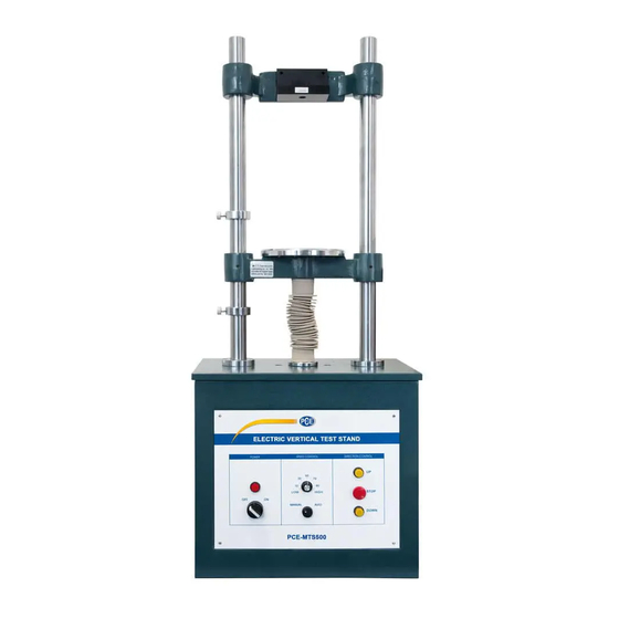
Test Stand for Force Gauge
PCE-MTS500
INSTRUCTION MANUAL
PCE Americas Inc.
711 Commerce Way
Suite 8
Jupiter
FL-33458
USA
From outside US: +1
Tel: (561) 320-9162
Fax: (561) 320-9176
info@pce-americas.com
www.pce-instruments.com/english
www.pce-instruments.com
PCE Instruments UK Ltd.
Units 12/13
Southpoint Business Park
Ensign way
Hampshire / Southampton
United Kingdom, SO31 4RF
From outside UK: +44
Tel: (0) 2380 98703 0
Fax: (0) 2380 98703 9
info@pce-instruments.com
Advertisement
Table of Contents

Subscribe to Our Youtube Channel
Summary of Contents for PCE Instruments PCE-MTS500
- Page 1 PCE Americas Inc. PCE Instruments UK Ltd. 711 Commerce Way Units 12/13 Suite 8 Southpoint Business Park Jupiter Ensign way FL-33458 Hampshire / Southampton United Kingdom, SO31 4RF From outside US: +1 From outside UK: +44 Tel: (561) 320-9162 Tel: (0) 2380 98703 0...
-
Page 2: Table Of Contents
CONTENTS 1.Function 2.Structure 3.Installation 4.Specification 5.Attention 6.Operation 7.Maintenance 8.Packing List... -
Page 3: Function
1. Function Electric Vertical Test Stand, applied in tension and compression test, is assembled with (2N-5kN) Series Force Gauge. The stand adopts double-column construction with good stability, wide application range and easy operation. Furthermore, it has advantages of non-polar speed adjustment, manual or automatic operation, suitable for fields of rubber & plastic products, textile, construction, complex material, wire &... -
Page 4: Installation
3.Installation of Force Gauge Joint Bearing M6 Haxangular Nut M3 Screw Force Gauge Sensor Outside Backboard Force Gauge Picture 1 Installation of Picture 2 Installation of Picture 3 Installation of Force Gauge(1kN-5kN) (Sensor Inside) Force Gauge Force Gauge 1. When installing (Sensor Inside) Force Gauge, take out 4 pieces of M3 screws from toolbox, and through 4 deep hole of Small Backboard, tighten them into 4 installing hole on force gauge(Picture 1);... -
Page 5: Attention
5.Attention A. Please do not take Up or Lower Limit Screw at any time to prevent screw mandrel from getting out or damaging to other accessories. B. When needing to move UP Slide Carriage for appropriate space, please pay attention: 1.


Need help?
Do you have a question about the PCE-MTS500 and is the answer not in the manual?
Questions and answers