
Related Manuals for PCE Instruments PCE-MCA 50


Summary of Contents for PCE Instruments PCE-MCA 50
- Page 1 User’s Manual UNIVERSAL CALIBRATOR PCE-MCA 50 PCE Instruments Email: info@pce-instruments.com Web: http://www.pce-instruments.com Doc. Ref. no.:mM12/om/201 Issue no. 00...
-
Page 2: Table Of Contents
Electrical warnings ............... 5 Cautions ..................5 Summary of functions ..............6 2. PCE-MCA 50 Hardware Parts & Accessories ..........7 2.1 Unpacking & Inspection ............7 2.2 Operational Sections and Connections ......8 2.2.1 The Terminal Connections ........... 8 2.2.2 The KeyPad ............... - Page 3 5.1 Common Problems ............. 72 5.2 Replacing the Battery ............73 5.3 Related Information ............73 5.3.1 Thermocouple Measurement/Simulation, Connections and troubleshooting..............74 5.3.2 Parallel Functions in PCE-MCA 50 ....... 76 6. General Specifications ................... 77 6.1 General Specifications ............78...
- Page 4 6.2 Display & Keys ..............78 6.3 Special Features ..............78 6.4 Power Supply ................ 79 6.5 Physical ................. 79 6.6 Electrical Measurement Parameters and Accuracy ..79 6.7 Electrical Simulation Parameters and Accuracy ....80 6.8 Resistance Measurement 0 ... 4000 ohm ......80 6.9 Resistance Simulation 0 ...
-
Page 5: Introduction
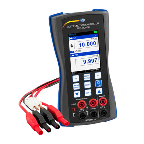
1. Introduction Foreword Thank you for purchasing Universal Calibrator PCE- MCA 50. The PCE-MCA 50 calibrator is compact hand- held calibrator with an easy to use graphical user interface. This manual describes the basic functions and operation methods. Please read through this user’s manual carefully before using the product. -
Page 6: General Warnings
General WARNING warnings It is dangerous to ignore the specified limits for the instrument or its related accessories. Do not use the instrument or accessory if it is not in its normal condition. Use the applicable protection and obey all safety precautions. -
Page 7: Summary Of Functions
Summary of This table gives a summary of the available functions with the PCE-MCA 50 calibrator. functions Function Easy to read liquid crystal display (LCD) in color Rechargeable lithium Ion battery with enhanced power control for prolonged battery life. * Measure RTD(Pt10, Pt50, Pt100, Pt200, Pt400, Pt1000,... -
Page 8: Pce-Mca 50 Hardware Parts & Accessories
2. PCE-MCA 50 Hardware Parts & Accessories 2.1 Unpacking & Inspection At the factory each new PCE-MCA 50 passes a careful inspection. It should be free of scrapes and scratches and in proper operation order upon receipt. The receiver should, however, inspect the unit for any damage that may have occurred during transit. -
Page 9: Operational Sections And Connections
All sections and connections are presented in detail on the next pages. Note: Keep in mind that the next picture (as well as all pictures of PCE-MCA 50 in this manual) has an example configuration of modules. The configuration of your PCE-MCA 50 may vary significantly from the one in the picture. - Page 10 ➢ mA Current Measurement In this mode PCE-MCA 50 not providing any supply voltage. For proper measurement the external device should capable of providing the voltage supply. If the external device should not capable, an external Power Supply should be connected in series.
- Page 11 ➢ mA Read Power Current Measurement In this mode PCE-MCA 50 works as Loop Power Supply while at the same time measuring the current. • Voltage Measurement PCE-MCA 50 is capable of voltage measurement. The following picture displays the connection for voltage measurement.
- Page 12 PCE-MCA 50 is capable to count number of pulses. The following picture displays the connection for pulse count measurement. Check the Trigger Level setting to specify the trigger level and whether to use a test voltage during the pulse counting. Also check...
- Page 13 Terminals for Simulating voltage, current, supplying loop power types refer specification sheet on page no. 79 Section 6.7 • Current Generation In source mode PCE-MCA 50 provides the supply power to the loop. The following picture displays the connection for current source for different mode.
- Page 14 PCE-MCA 50 is capable of RTD/Resistance generation. following picture displays the connection for RTD and Resistance simulation. In RTD simulation PCE-MCA 50 mimics an RTD. The instrument under test generates the current for the RTD measurement.PCE-MCA 50 controls the voltage across its terminals so that the resistance (voltage to Current ratio) corresponds to the simulated temperature.
- Page 15 ➢ 4-Wire RTD Measurement PCE-MCA 50 sources current through the resistor from two left side terminals and measure the voltage drop across the resistor from the two right side terminals. The 4-wire method gives the...
- Page 16 7.9 mm (0.312 in) center to center. For specification refer Section 6.12 PCE-MCA 50 supports measurement and simulation of Thermocouple and mV. ➢ Frequency Terminals PCE-MCA 50 is capable of Frequency Generation.
- Page 17 ➢ Pulse Terminals PCE-MCA 50 is capable of Pulse Generation. The following picture displays the connection for Pulse Generation. For specification refer Section 6.16...
-
Page 18: The Keypad
2.2.2 The KeyPad PCE-MCA 50 has nine different keys. The key description is given below. This key has different functionalities in different menu. And that is shown on Bottom Left Part of Display. Pulse Resetting Shortcut: The counter may be cleared (zeroed) by long Pressing F1 key for 3 sec during Pulse Measurement Only. -
Page 19: The Display
Mode and Icon Details 2.2.4 The USB Connection • The USB Connection Connector is given at Top of the PCE-MCA 50. It’s a USB A Male to USB mini B Male Connector. • It is common for PC Communication & Charging the device. -
Page 20: Power Options
2.3 Power Options There are three power options: • Lithium-Ion battery: All the instrument functions are available with a charged battery. • 5 V DC Charging Adaptor: It supplies power to the instrument and charges the battery at the same time. It charges the battery when the instrument is on or off. -
Page 21: Operating Time
50 is not in use. ➢ Do not leave PCE-MCA 50 without a Battery Pack or an Empty Battery for a long time. PCE-MCA 50 may lose its settings if it is left without a support voltage for an extended period. -
Page 22: Start Up & Basic Operations
When the power is off, the last set of configuration options stays in memory. 3.2 The User Interface Every time PCE-MCA 50 is switched on, the startup message ends in RUN Page. There are 5 Display Mode available in RUN Page. -
Page 23: The Status Bar
3.2.1 The Status Bar The Status Bar at the top of the display is visible only in RUN Page. It is divided into five main sections. Time in HH:MM:SS Format Available in Two Format 1. 24 Hour (default) 2. 12 Hour This setting is available in Date/Time in Settings Menu Error Code Indicator This Icon is visible if any On-Board Peripherals like RTC, ADC, DAC, etc. -
Page 24: The Function Key Bar
3.2.2 The Function key Bar The Function Key Bar at the bottom of the display is visible all the time. There are 2 Function Key Available. The meaning of the Function Keys varies depending on the situation. A Blank Function key text means that the function is disabled at the moment. - Page 25 Display Mode RTD Mode Shows the Current RTD Mode RTD Measure Mode RTD Source Mode RTD Type Shows the current RTD Type. Wire Selection Wire connection for RTD and Resistance Measurement / Source 2 wire connection 3 wire connection 4 wire connection Reading Shows the RTD reading according to RTD Type.
- Page 26 TC (Measure/Source) + EM Measure Mode / Switch Test Mode Display Mode Input Type The Input Type. Display The Measure Reading Display Mode. Mode Actual Displays the Raw Input Value without any scaling Percentage Displays the Percentage Value. Reading The Reading as per the Measure Display Mode Bar Graph Horizontal Bar graph according to Input Percentage Value (0.00% - 100.00%).
- Page 27 Measure Window Input Type The Input Type. mA Current Input mA(24V) mA Current (Read Power-24V) Input V Voltage Input Measure Display Mode The Measure Reading Display Mode. Actual Displays the Raw Input Value without any scaling Percentage Displays the Percentage Value in (0.00% - 100.00%) Scaled Displays the Scaled Value...
- Page 28 Display Mode Input Type The Input Type. mA Current Input mA(24V) mA Current (Read Power-24V) Input V Voltage Input Display Mode The Measure Reading Display Mode. Actual Displays the Raw Input Value without any scaling Percentage Displays the Percentage Value. Scaled Displays the Scaled Value Reading...
- Page 29 Pulse Output + EM Measure Mode / Switch Test Mode Pulse Output Pulse mode The Input Type. Pulse type The Pulse type. Symmetric Displays the symmetric pulse type Positive Displays the Positive Pulse type Duty Cycle Duty Cycle Percentage Value (the ratio of the output high time to the total cycle time) Reading The Reading as per the Display Mode...
- Page 30 Frequency Output + EM Measure Mode / Switch Test Mode Frequency Output Frequency mode The Input Type. Frequency type The Frequency type. Symmetric Displays the symmetric pulse type Positive Displays the Positive Pulse type Duty Cycle Duty Cycle Percentage Value (the ratio of the output high time to the total cycle time) Reading The Reading as per the Display Mode...
-
Page 31: Display Operations
3.2.4 Display Operations There are mainly four types of widgets available in the Device Menu Style. ListBox EditBox iii. CheckBox RadioButtonBox The below section will show how to change the value of different widgets. • ListBox ListBox are used when there is a limited amount of preset values. You have to select one of the available options. - Page 32 • EditBox Edit Box is used where a large range of value can be possible for a parameter. To edit the value of an EditBox press F1 key. After that EditBox enters into the Edit mode where F1&F2 keys are works as shifter. User can shift to desired digit and using UP or DOWN key digit value can be increment or decrement.
- Page 33 There are mainly 2 types of EditBox in this device. In most of the EditBox changing of decimal point & changing of sign is not allowed. But there are few EditBox, where these are allowed. Examples Scaled Low (0%) &High (100%) etc. The below figure shown the example how to change decimal point of the Input Scaled High (100%) Range.
- Page 34 CheckBox is used where Binary Value (1/0, True/False) is available for any parameter. To change the CheckBox status press F1 key. This will enter into the edit mode. In this mode status can be toggled by pressing F1 key. Press MENU/ENT key to store new status.
- Page 35 • RadioButtonBox RadioButtonBox is used where very few values can be possible and all the available values need to be visible. In this device, two types of RadioButtonBox are available. One with 1 value can be selectable & the other where 1 or 2 values can be selectable at a time.
-
Page 36: Scr1 And Scr2 Key Option : Mquick-Setup Key
3.2.5 SCR1 and SCR2 Key Option : mQUICK-SETUP Key PCE-MCA 50 has divided the RUN Screen into Two Parts: SCR1 and SCR2 as shown in below figure. Both windows can independently be configured to display a measurement value. SCR1 Display... -
Page 37: Menu Layout
4. Menu Layout 4.1 MENU page There are mainly eight Menus in this device. To enter into the MENU page press MENU/ENT key & press F2 key to come out from Menu page. Contains Parameters related to EM Measure Mode like Input EM SETUP Type, Range etc. - Page 38 Parameter Name Description / Options I/P Type Measure Input Type (Input Type) Available Options: 0.000 to 24.000 mA DC mA(24V) 0.000 to 24.000 mA DC 0.000 to 30.000 V DC Pulse 0 to 999999 Pulses Frequency 0.0143 to 50000Hz Input Range Low Range for Measure Input.
-
Page 39: Source Page
Available Options: Rising Edge Falling Edge Unit Unit for Frequency Measure input Available Options: 1/Hz (s) 1/KHz (ms) Trigger Level (V) Trigger level for Pulse and Frequency Measure input Available Options: 0 to 7 V 4.3 SOURCE Page 4.3.1 ET Setup This Page is appears in MENU ET SETUP. - Page 40 Output Range Low Range for Source Output. Low (0%) Range: Default Output Low to Output Range High (100%) This parameter is enabled, if Main Display in MENU →DISPLAY →SOURCE is set to Percentage orScaled. Output Range High Range for Source Output. High (100%) Range: Output Range Low(0%)to Default Output High...
- Page 41 • STEP Page: Parameter Description / Options Name Manual Step Manual Mode Selection CheckBox. (Output Type) Ticking this checkbox will enable Step Manual Mode. And Un-ticking will enable Auto Step Mode. Step Time (s) Enter the time for a single step in seconds, Range: 1 to 9999 This parameter is enabled only for Auto Step Mode (Manual CheckBox is...
- Page 42 DOWN UP/DOWN DOWN/UP This parameter is enabled only for Auto Step Mode (Manual CheckBox is Un-Checked) Repeat Defines how many times the steps arerepeated Repeat Counts Range: 1 to 9999 This parameter is enabled only for Auto Step Mode (Manual CheckBox is Un-Checked) ➢...
- Page 43 Automated Step can be started by Pressing F1 key (START). After that & will change PAUSE&STOPrespectively. So by pressing F1 & F2 key running STEP can be PAUSE or STOP at any time in RUN Page. STEP Setting can be accessed directly by F2 key (SETTING). Note: While STEP is running STEP settings can’t be accessible and Source Page Parameter settings can’t be change.
- Page 44 Available Options: DOWN UP/DOWN DOWN/UP Repeat Defines how many times the steps arerepeated Repeat Counts Range: 1 to 9999 ➢ Starting the RAMP To Enable Ramp, select Source Type as RAMP. If this mode is enabled, (Rising Ramp) or (Falling Ramp) ) or ) icon will appear Ramp Hold @ 100%...
-
Page 45: Tc Setup
4.3.2 TC Setup This Page is appears in MENU TC SETUP. → → This page contains parameters related to Thermocouple like TC Mode Type, TC Type, Unit, TC Source Mode etc. The Description of the Parameters appear on this page is given below. Parameter Description / Options Name... - Page 46 Source Mode TC Source Output Format This option appear only if TC Mode is SOURCE. Available Options: STEP RAMP At a time one can be selectable. Press F1 key on the one of the option for more settings. Reset Reset the Additional Information of Measure mode like Minimum & Additional Info.
- Page 47 Step Definition Step Definition for the Step function. Available Options: Temperature (Appear only if TC Display mode is Actual) Percentage (Appear only if TC Display mode is Percentage) User Defined Step Step Value in Temperature/mV/% according to TC Display Mode and TC unit. Only appear if Step Definition is Temperature or Percentage.
-
Page 48: Rtd Setup
• RAMP Page: Parameter Description / Options Name Starting Value of Ramp. Enter value according to TC Display Mode. If display mode is actual enter value in temperature/mV and if display mode is % enter value in %. Ending Value of Ramp. High Enter value according to TC Display Mode. - Page 49 This Page is appears in MENU RTD SETUP. → → This page contains parameters related to RTD like RTD ModeType, RTD select, Unit, RTD Source Mode etc. The Description of the Parameters appear on this page is given below. Parameter Description / Options Name RTD Mode...
- Page 50 Parameter Name Description / Options Starting Value of Step. Enter value according to RTD Display Mode. If display mode is actual enter value in ohms/°C and if display mode is % enter value in %. Ending Value of Step. Enter value according to RTD Display Mode. If display mode is High actual enter value in ohms/°C and if display mode is % enter value in %.
- Page 51 Repeat Format How the stepping should be done. Available Options: DOWN UP/DOWN DOWN/UP This parameter is enabled only for Auto Step Mode (Manual CheckBox is Un-Checked) Repeat Defines how many times the steps are repeated Repeat Counts Range: 0 to 9999 (0=infinity) This parameter is enabled only for Auto Step Mode (Manual CheckBox is Un-Checked)
- Page 52 • RAMP Page : Parameter Description / Options Name Starting Value of Ramp. Enter value according to RTD Display Mode. If display mode is actual enter value in ohms and if display mode is % enter value in %. Ending Value of Ramp. High Enter value according to RTD Display Mode.
- Page 53 • Continuity Test: Parameter Name Description / Options Continuity Feature Selection Radiobuttonbox. Continuity Feature Selecting radiobuttonbox will enable continuity feature for RTD Measure Mode. Enter the threshold value of resistance up to which continuity test is applied. Threshold Range: 0 to 100 When Testing Continuity Beep sounds and continuity symbol appear on run page as shown in below figure.
-
Page 54: Pulse Setup
4.3.4 Pulse Setup This Page is appears in MENU PULSE SETUP. → → This page contains parameters related to Pulse and Frequency like Pulse type, Amplitude (Vpp), Unit, Frequency, Duty Cycle (%) etc. The Description of the Parameters appear on this page is given below. -
Page 55: Display Page
Parameter Description / Options Name Pulse Type Pulse Type Available Options: Symmetric Displays the symmetric pulse type Positive Displays the Positive Pulse type Amplitude(Vpp) Select the Amplitude of Pulse or Frequency Unit Frequency Unit Available Options: 1/Hz (s) 1/KHz (ms) This Option appear only if Frequency mode is selected. - Page 56 In this page there is one RadioButtonBox. At a time two option can be selected. The possible combinations are given below. EM + ET EM + TC EM + RTD EM + Pulse Generation Switch Test + ET Switch Test + TC Switch Test + RTD Switch Test + Pulse Generation...
-
Page 57: Em Display Settings
4.4.1 EM Display Settings This Page is appears in MENU DISPLAY EM Terminal. → → → Parameter Description / Options Name Main Display Select which Reading to be display as a Main Reading (Reading Displays in Box in RUN Page). Available Options: Actual Display the Actual Input Value... -
Page 58: Switch Test Display Settings
4.4.2 Switch test Display Settings This Page is appears in MENU DISPLAY SWITCH TEST. → → → Parameter Description / Options Name Mode Switch Test Operation Mode Available Options: 2V(24Vdc,26mA) Switch Close when External Switch (Potential Free Contacts) short & Switch Open is External Switch open. -
Page 59: Display Settings
4.4.3 ET Display Settings This Page is appears in MENU DISPLAY ET Terminal. → → → Parameter Description / Options Name Main Display Select which Reading to be display as a Main Reading (Reading Displays in Box in RUN Page). Available Options: Actual Display the Actual Output Value... -
Page 60: Tc Display Settings
4.4.4 TC Display Settings This Page is appears in MENU DISPLAY TC Terminal. → → → Parameter Description / Options Name Main Display Select which Reading to be display as a Main Reading (Reading Displays in Box in RUN Page). Available Options: Actual Display the Actual Thermocouple/mV Value... - Page 61 Temperature including CJ temperature mV. The mV which is sourced through TC Terminal. Shows the Feedback Temperature/mV Reading. When PCE-MCA 50 generate mV, it uses its Reading own measurement function to control the Feedback generated value. This feedback measurement is shows if this option is selected.
-
Page 62: Rtd Display Settings
4.4.5 RTD Display Settings This Page is appears in MENU DISPLAY RTD Terminal. → → → Parameter Description / Options Name Main Display Select which Reading to be display as a Main Reading (Reading Displays in Box in RUN Page). Available Options: Actual Display the Actual RTD/Resistance Value... - Page 63 Options Icon Description None No info is visible. Shows the Actual RTD Temperature/ohms value without any scaling. Actual Value This option is available only if RTD Display Mode is Percentage. Excitation Shows the current which is sourced by Current instrument under test. Filter(sec) Order IIR Low Pass Filter for RTD Measure Reading.
-
Page 64: Data Logging Page
4.5 DATA LOGGING Page This section gives examples of how to log Readings with time and date over a set time period or on a key press. Logged data is stored in a user defined file in internal memory. This Page is appears in MENU LOGGING. - Page 65 Sampling Sampling Rate for Periodic Data Logging in seconds. Rate(s) Range: 1 to 9999 This parameter is enabled only for Periodic Trigger. Logging Time Total Logging Time in HH:MM:SS Format for Periodic Logging. (HH:MM:SS) This parameter is enabled only for Periodic Trigger. File No.
-
Page 66: Transferring The Results To A Personal Computer
4.5.1 Transferring the Results to a Personal Computer: A 32-bit Windows® software called mCAL+.exe is shipped together with PCE-MCA 50 if you bought the Data Logging option. Start this software just as any other Windows® software. All communication between the PC and PCE-MCA 50 is initiated from mCAL+.exe. -
Page 67: Cjc Setting Page
4.6 CJC SETTING Page 0This Page is appears in MENU CJC Settings. → → Parameter Description / Options Name CJC Mode CJ (Cold Junction) Temperature Mode Available Options: AUTO CJ Temperature is TC Terminal’s temperature. CJ Temperature is user selectable irrespective of MANUAL TC Terminal temperature. -
Page 68: Wire Select Page
4.7 Wire Select Page This Page is appears in MENU WIRE SELECT. → → Parameter Description / Options Name Detection Mode Wire Detection Mode Available Options only for Measure: AUTO Automatic detect the wire connection. MANUAL Manually Select the wire connection Wire Selection Manually Select the wire connection Available Options:... -
Page 69: Alarm Page
Individual alarm limit values may also be enabled/disabled using the check box preceding the alarm limit value. When an alarm limit is exceeded, PCE-MCA 50 emits an audible alarm and the Main Reading is shown with RED Color. To stop alarm uncheck the appropriate alarm checkbox. -
Page 70: Setting Page
4.9 SETTING Page This Page is appears in MENU SETTING. → → All the available Settings Options are given below. HART Display iii. Date/Time Calibration Battery Info. Set Password vii. Factory Reset viii. About Us Press F1 key to Enter into the settings of any option. Description of all settings given below. -
Page 71: Display Settings
4.9.2 Display Settings Display Display Brightness Settings. Intensity Range: 5 to 100 Screen Mode Screen Mode Available options: Glance screen Always on Glance Screen Standby Time in second after Time Out which display will turn Off. To turn the display on press any key. -
Page 72: Calibration
4.9.4 Calibration Each PCE-MCA 50 comes factory calibrated. To have the meter re- calibrated, please get in touch with PCE Instruments. Unintended changes made in the internal calibration menu can cause problems / inaccuracies. 4.9.5 Battery Info. This page shows the basic battery Information. -
Page 73: Factory Reset
4.9.7 Factory Reset To Reset PCE-MCA 50 Parameters to its Default Value. To Reset Enter Current Password. If the entered password correct then Configuration RESET Radiobuttonbox will be enabled. Then select YES option and press MENU/ENT Key to reset Configuration. -
Page 74: Replacing The Battery
5.2 Replacing the Battery... -
Page 75: Related Information
The subjects described here are: • Thermocouple Measurement/Simulation, Connections and troubleshooting on page no 86. • Parallel Functions in PCE-MCA 50 on page no 89. 5.3.1 Thermocouple Measurement/Simulation, Connections and troubleshooting. To accurately measure the thermo-voltage caused by the temperature to be measured, the second thermo-voltage caused by the Reference Junction needs to be compensated. - Page 76 Reference Junction Mode: ➢ External Reference Junction When using an external Reference Junction, PCE-MCA 50 measures or simulates the thermo-voltage using the “T/C” terminals. The following external Reference Junction compensation methods are available, To select this compensation method, set the SCR1 field “T/C Sensor Measurement”...
- Page 77 PCE-MCA 50 (or the • Incorrect connections. instrument under test) • The wiring is broken. displays random readings • Interference from a mobile phone or during a radio transmitter affects the Thermocouple measurement. measurement. 5.3.2 Parallel Functions in PCE-MCA 50...
-
Page 78: General Specifications
(CJC Mode field set to External RTD). Additionally, all of the connectors on the left side of PCE-MCA 50 may have an independent task. Below Illustrate the Possible Parallel Functions of PCE-MCA 50. -
Page 79: General Specifications
6.1 General Specifications Display Mode Measure: mA/V/mV/mA(2W)/Switch-test /RTD/TC/Frequency/Pulse Source: mA/V/mV/mA(2W)/Resistance/RTD/TC/Frq./P ulse Supported units for RTD/TC type °C/°F/°K RTD Measurement Current 300 uA Maximum Resistance 3 mA (0...650 Ω measure/source with excitation current I exec 2.0V/ Rsim (650..4000Ω) (simulation) Settling time >1 ms (pulsed currents RTD simulation) CJC error (For Thermocouple) -
Page 80: Power Supply
Loop power output 24V DC, +10% (24mA maximum) HART mA Loop 250 Ω + 20% Resistor Special Function Step/Ramp functions: Automatic/Manual. : for mA/V measure/source Continuity Test Audible sounds when resistance measure value crosses the specified threshold. (selectable up to 100Ω) Automatic Wire Automatic detection RTD measure wire connection. -
Page 81: Electrical Simulation Parameters And Accuracy
0-24.00 mA 0.001 mA +0.02% of reading + 2 count 6.7 Electrical Simulation Parameters and Accuracy Parameter Range Resolution Accuracy 0-12.00 VDC 0.001 V +0.02% of reading + 2 count 0-24.00 mA 0.001 mA +0.02% of reading + 2 count 6.8 Resistance Measurement 0 ... -
Page 82: Rtd Measurement And Simulation
6.10 RTD Measurement and Simulation 1) Pt10 …… Pt1000, -200 …… 850 ºC Range Resolution Accuracy -200….200 °C Pt10…Pt400: 0.01 4 wire Measurement: 0.15°C °C Simulation*: 0.15 °C 200….600 °C 4 wire Measurement: 0.2 °C Pt500,Pt1000: 0.1 Simulation*: 0.25 °C °C 600….850 °C 4 wire Measurement: 0.3 °C... -
Page 83: Thermocouple/Mv Resolution And Accuracy
6.12 Thermocouple/mV Resolution and Accuracy TC Terminal (Measure and Source) TC Type Range Resolution Accuracy -200.0 to 1000.0 °C 0.1 °C 0.3 °C -200.0 to 1200.0 °C 0.1 °C 0.3 °C -200.0 to 1372.0 °C 0.1 °C 0.3 °C -200.0 to 400.0 °C 0.1 °C 0.3 °C 450.0 to 1800.0 °C... -
Page 84: Pulse Generation
Feature Specification Output Amplitude positive Square wave 0 to 12VPP (±0.25V + 5%) Output Amplitude symmetric Square 0 to 6 VPP (±0.25V + 5%) wave Accuracy 0.01% of Reading ± 1 count Duty Cycle 1 to 99 %( 0.0009 to 500Hz),High to low time: minimum 25us. -
Page 85: Enclosure Dimensions
6.17 Enclosure Dimensions *All dimensions are in mm.
Need help?
Do you have a question about the PCE-MCA 50 and is the answer not in the manual?
Questions and answers