TSI Instruments AEROTRAK 9310 Operation Manual
Portable airborne particle counter
Hide thumbs
Also See for AEROTRAK 9310:
- Operation manuals (89 pages) ,
- Operation manual (77 pages) ,
- Quick start manual (4 pages)

Related Manuals for TSI Instruments AEROTRAK 9310


Summary of Contents for TSI Instruments AEROTRAK 9310
- Page 1 AEROTRAK ® PORTABLE AIRBORNE PARTICLE COUNTER MODEL 9310/9350/9510/9550/9500 OPERATION MANUAL P/N 6004217, REVISION S MARCH 2018...
- Page 3 AEROTRAK ® PORTABLE AIRBORNE PARTICLE COUNTER MODEL 9310/9350/9510/9550/9500 OPERATION MANUAL P/N 6004217, Revision S March 2018 SHIP TO/MAIL TO: E-mail address: TSI Incorporated answers@tsi.com 500 Cardigan Road Shoreview, MN 55126-3996 Website: http://www.tsi.com U.S. INTERNATIONAL Technical Support: Technical Support: (800) 874-2811/(651) 490-2811 (001 651) 490-2811 Fax: Fax:...
-
Page 4: Manual History
M a n u a l H i s t o r y The following is a manual history of the AeroTrak ® Portable Airborne Particle Counter, Model 9310, 9510, 9350, 9550, 9500 Operation Manual (P/N 6004217). Revision Date Revision Date July 2010 January 2014... -
Page 5: Warranty
W a r r a n t y Part Number 6004217 / Revision S / March 2018 Copyright ©TSI Incorporated / 2010-2018 / All rights reserved. Address TSI Incorporated / 500 Cardigan Road / Shoreview, MN 55126 / USA E-mail Address answers@tsi.com (For country-specific terms and conditions outside of the USA, please visit www.tsi.com.) Limitation Of Warranty And Liability... - Page 6 REINSTALLATION COSTS OR CHARGES. No Action, regardless of form, may be brought against Seller more than 12 months after a cause of action has accrued. The goods returned under warranty to Seller's factory shall be at Buyer's risk of loss, and will be returned, if at all, at Seller's risk of loss.
-
Page 7: Table Of Contents
C o n t e n t s Manual History .................... ii Warranty ..................... iii Contents ...................... v Safety Information ..................vii Laser Safety .................... vii Labels ...................... viii Description of Caution/Warning Symbols ..........ix Caution ....................ix Warning ....................ix Caution or Warning Symbols .............. - Page 8 Configuration Screen ..............3-20 Print Setup Screen ................. 3-22 Print Schedule Screen ..............3-23 Clear Samples Screen ..............3-24 Purge Screen ................. 3-25 Information Screen ................ 3-26 Device Setup Screen ..............3-26 Date and Time Screen ..............3-27 Display Screen ................3-28 Communications Screen ..............
-
Page 9: Safety Information
S a f e t y I n f o r m a t i o n This section gives instructions to promote safe and proper handling of the AeroTrak ® Portable Airborne Particle Counter. I M P O R T A N T There are no user-serviceable parts inside the instrument. -
Page 10: Labels
L a b e l s Advisory labels and identification labels are attached to the outside of the particle counter housing and to the optics housing on the inside of the instrument. 1. Serial number label (back panel) 2. Laser radiation label (internal) 3 Laser instrument compliance label... -
Page 11: Description Of Caution/Warning Symbols
D e s c r i p t i o n o f C a u t i o n / W a r n i n g S y m b o l s Appropriate caution/warning statements are used throughout the manual and on the instrument that require you to take cautionary measures when working with the instrument. -
Page 12: Getting Help
G e t t i n g H e l p To obtain assistance with this product or to submit suggestions, please contact Customer Service: TSI Incorporated 500 Cardigan Road Shoreview, MN 55126 U.S.A. Fax: (651) 490-3824 (USA) Fax: 001 651 490 3824 (International) Telephone: 1-800-874-2811 (USA) or (651) 490-2811 International: 001 651 490 2811 E-mail Address:... - Page 13 C H A P T E R 1 I n t r o d u c t i o n a n d U n p a c k i n g The AeroTrak ® Portable Airborne Particle Counter (particle counter) has a touch-screen interface and operates on the included lithium-ion battery or AC power.
- Page 14 U n p a c k i n g t h e A e r o T r a k ® A i r b o r n e P a r t i c l e C o u n t e r Carefully unpack the AeroTrak ®...
-
Page 15: Chapter 1 Introduction And Unpacking
Qty. Item Description Part/Model Reference Picture Computer Cable 700033 (2 m), USB A to B Stylus HEPA Zero Filter 700119 (for the Assembly 28.3 and 50 L/min model) 700098 (for the 100 L/min model) TrakPro™ Lite 7001901 Secure Software CD for 21 CFR Part 11 compliant data downloading (includes manuals) -
Page 16: Optional Accessories
Optional Accessories The following photos and table list optional accessories. If you ordered optional accessories, make certain they have been received and are in working order. ® AeroTrak Portable Airborne Particle Counter Optional Accessories Item Description Part/Model Reference Picture Stainless Steel Isokinetic 700069 Probe (used with tubing) (28.3 L/min)700026... - Page 17 Item Description Part/Model Reference Picture Velocity/Temperature 960 (Straight) Probe 962 (Articulated) Temperature/RH Probe 700097 with Cable Carry Case 700086 Heavy Duty Carry Case 700087 (rolling case) Introduction and Unpacking...
- Page 18 (This page intentionally left blank) ® AeroTrak Portable Airborne Particle Counter...
- Page 19 C H A P T E R 2 G e t t i n g S t a r t e d This chapter describes the features, connections, and installation of the AeroTrak ® Portable Airborne Particle Counter (particle counter). It includes: ...
-
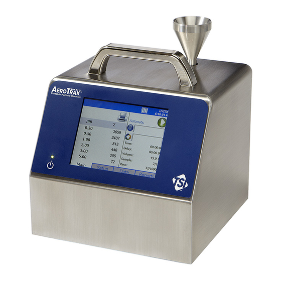
Page 20: Instrument Description
I n s t r u m e n t D e s c r i p t i o n The AeroTrak ® Portable Airborne Particle Counter has many features to make measurements convenient. The power switch is located on the front panel in the lower-left. - Page 21 Description Function Alarm This connector provides two pins for a contact closure to control an external alarm. The contact closure is normally open and rated for 0 to 60 V AC/DC at 1.5A peak, 0.5A continuous. The “alarm out” connection is rated for 60 V insulation.
-
Page 22: Providing Power
P r o v i d i n g P o w e r These particle counters may be powered using rechargeable lithium-ion batteries (from one to four) or through an AC power cord. N O T E S When using AC power, the battery (if installed) charges when the instrument is on, while actively sampling (trickle charging), and when the power is put in standby—charge battery mode. -
Page 23: To Install The Lithium-Ion Battery
To Install the Lithium-Ion Battery 1. Remove the battery door on the back of the instrument by turning the two thumbscrews counterclockwise. 2. One battery is provided for the 28.3 and 50 L/min models, but up to two batteries can be used to extend the run time. Two batteries are provided for the 100 L/min model (Model 9500) and both must be present for the unit to operate on batteries. -
Page 24: To Use Ac Power
To Use AC Power Connect the country-appropriate power cord to the external power supply. Next connect the 24 VDC connector to the socket in the particle counter and then connect the other end to an AC outlet. W A R N I N G The instrument turns on automatically when the AC power supply is plugged in. -
Page 25: Using The Integral Thermal Printer
U s i n g t h e I n t e g r a l T h e r m a l P r i n t e r The side-mounted integral thermal printer is standard on most models to print manually, automatically after each test is completed, or whenever the alarm function is activated (see Print Setup Screen... -
Page 26: Using Peripherals
The printer has a feed and stop button as well as an LED indicating that the printer is ready. The feed button can be held down at the end of a print to allow enough space to tear off the paper. If you unintentionally start a print (especially something very long), stop printing with the stop button. -
Page 27: Filter Scanner
W A R N I N G When connected to the alarm out connector, you must use safety certified equipment and/or power sources. Filter Scanner This connector is used with the optional TSI Electronic Filter Scanner (TSI P/N 700103). Plugging in the connector from the Electronic Filter Scanner allows you to start and stop a sample from the probe head. -
Page 28: Alarm
Alarm This connector is used to communicate the alarm status of the instrument. When the instrument is in flow or laser alarm, the dry relay will close. The mating connector and ferrite is provided. The user must supply the wiring. Install the clamp-on ferrite so that it is within 1 inch of the connector as shown. -
Page 29: Using Communications Ports
U s i n g C o m m u n i c a t i o n s P o r t s USB B (to Ethernet computer) Port USB B The standard USB B connector is used to connect the instrument to a ™... -
Page 30: Using An Isokinetic Probe
U s i n g a n I s o k i n e t i c P r o b e The isokinetic probe smoothly accelerates air into the inlet of the instrument. The barbed isokinetic probe can be used with tubing and an adjustable tripod mount (not included) to monitor particles in hard to reach places or that are flowing horizontally. - Page 31 C H A P T E R 3 O p e r a t i o n The AeroTrak ® Portable Airborne Particle Counter is controlled using a touch screen display. Use the plastic stylus or your finger tip. DO NOT use sharp objects (such as a pen point) that may damage the screen overlay.
-
Page 32: Screen Layout And Functionality
S c r e e n L a y o u t a n d F u n c t i o n a l i t y There are four main screens (tabs): Main, Setup, Data, and Reports. The operation of each of these screens, the information displayed on them, and the operations you can perform from each are described in the remainder of this chapter. - Page 33 The status bar at the top of the screen shows the current time and date settings (see the Setup Tab) and indicates: Icon Description Instrument status error. If this icon is shown, it can be pressed and a more detailed description of the operational error will be shown. Refer to the troubleshooting section for appropriate actions.
- Page 34 Field Description Displays the zone where the sample is being taken by the instrument. Press the icon to display a (Zone) summary of information for the zone. This dropdown box allows selection of a (Location) preconfigured Location to associate the sampled data to.
- Page 35 1D barcode scanners that support USB 1.0 or 1.1 devices can be used (Zebra LS2208 works well) to select an existing Zone and Location pair in the list boxes on the Main page, if the barcodes use the format ZoneName:LocationName (i.e., the zone name followed by a colon followed by the location name).
-
Page 36: Zoomed Data Screen
Zoomed Data Screen The Zoomed Data screen is entered by touching in the size and count part of the main tab display. The bottom portion of the screen summarizes the concentrations for the currently selected location. Tap the size and count portion of the display to switch back to the Main Tab display. -
Page 37: Setup Tab
Setup Tab The setup tab provides access to the following: Zones Setup Identify and save the location information associated with collected samples. Recipes Setup Save a group of settings (a recipe) that you use over and over so you don’t have to reset individual settings. Environment Setup Sets which units are preferred for displaying environmental measurements taken using optional... -
Page 38: Zone Setup Screen
Zone Setup Screen “Zones” are a convenient way to group sample data for printing and export, and are required for creating standards-based classification reports. A Zone contains 1 or more “Locations;” this is modeled after cleanroom standards that prescribe the classification of a zone (or room) by taking samples at various locations within the zone. - Page 39 To Delete A Zone To delete a zone from the configuration screen, select (highlight) the zone name and press Delete. A verification message “Are you sure you want to delete this Zone?” appears. Press Yes to delete the zone. A zone that has data associated with it cannot be deleted. The data associated with the zone must be deleted from the instrument before the zone can be deleted.
- Page 40 3. Enter names for each location in the zone and the press Add after entering each. The name will be added to the box on the left side of the screen. 4. Press the Recipe tab. The Recipe screen is displayed with a default recipe in the “Selected Recipe”...
- Page 41 4. The Locations Screen displays the locations within the selected zone. You can add, rename, or remove a location from the zone. You can also move the location name up or down in the list. The Auto feature will generate the number of locations required by the chosen standard.
-
Page 42: Recipes Setup Screen
NO T E If you edit a recipe, the changes will affect all zones using that recipe. Be certain that is what you want to do. 7. When all the changes have been made, press Save. Recipes Setup Screen Use the Recipes Setup screen to review recipes, add or delete recipes, and edit recipes. - Page 43 The steps for adding or editing a recipe are identical. Press either the Add button or the Edit button and proceed as follows: 1. Press Add or Edit button to display the Recipe Tab. 2. On the Recipe tab, enter a name or edit the name of the recipe. For a new recipe, a default name will appear, but you can type over it and name the recipe anything you want.
- Page 44 Field Description Beep If multiple alarms are configured, the AeroTrak particle (continued) counter will emit beeps only on a single channel. If multiple alarms are configured, the AeroTrak particle counter searches for which alarm to operating on starting with the smallest to largest Total Particulate Channel selected followed by the smallest to largest Viable Particulate Channel.
- Page 45 W A R N I N G Instrument status alarms are inactive if samples times are 10 seconds or less. Flow error alarms may not occur if sample time is less than 15 seconds. To ensure proper instrument status and flow alarm operation, utilize a sample time of 15 seconds or larger.
- Page 46 7. Press the Channels tab. 8. This tab can be used to view or set the particle size for each channel (not supported in all models), enable/disable the channel, enable/disable alarm for each channel and set the alarm threshold for each channel.
-
Page 47: System Setup Screen
NO T E The Channel Configuration screen has restrictions that must be noted when Differential mode () is selected. When differential Δ particle count or concentration is selected, the total number of counts is the number of particles between enabled bin sizes. - Page 48 password is regarded as no password and if set as the new password, will not prompt you for a password on system startup. NO T E Keep the password in a safe place. It is difficult to reset the password and requires contacting the factory.
-
Page 49: Change Setup Password Screen
Change Setup Password Screen If a Setup password has been previously set, that password must be entered before being allowed to change the Setup password. If a Setup password is set, clicking on the setup tab at the bottom of the main screen brings up a password screen. - Page 50 Configuration Screen Use the Configuration screens to set configuration parameters. Press OK when finished. Field Description and on Zoom Select to zoom in on both cumulative (Σ) and differential (Δ) counts on the Main Tab. To zoom the Main Tab, select on the left side of the Main Tab (it takes a moment for the screen to update.) Click on the screen again to return to normal view.
- Page 51 Field Description Relay Trigger Check the box or boxes for the icon or icons upon which the relay trigger will close. Relay will close on instrument status errors including laser error, algorithm corruption, or select control voltages. Relay will close on any flow error including sample flow, sheath air flow, or concentrator flow.
- Page 52 Print Setup Screen A hard copy of a sample set or statistics can be printed from the instrument using an optional thermal printer. Use this screen to set print parameters. Press OK when finished. These selections will apply when printing automatically or when printing from the Data tab page. Field Description Serial Number...
- Page 53 Print Schedule Screen Use the Print Schedule screen to schedule automatic printing. Choose to either print when an alarm occurs or print whenever a sample is complete. “English Only Printing” can be selected to print reports in English even when the selected language is a language other than English. Prints default zones and locations in English.
- Page 54 Clear Samples Screen Use the Clear Samples screen to clear all samples from the internal database. Select Yes to clear all samples. Select No to return to the System Setup screen. C A U T I O N WHEN “YES” IS SELECTED ON THE CLEAR SAMPLES SCREEN, ALL SAMPLE RECORDS WILL BE DELETED FROM THE INSTRUMENT! THERE IS NO WAY TO RECOVER THEM ONCE THEY HAVE BEEN DELETED.
- Page 55 Purge Screen Use the Purge feature to improve zero count test by removing any residual particles in the flow path and depositing them on the exhaust filter. TSI recommends that this feature be used when: 1. The instrument was exposed to high concentrations. 2.
- Page 56 Information Screen Use the Information screen to view the system’s model, serial number, copyright, manufacture date, calibration date, next calibration date, firmware version, USB IP address and date and time format. Press Close when finished. Device Setup Screen Use the Device Setup screen to access screens to set or change the date and time, set visual parameters of the display, set up communications, or set regional features.
- Page 57 Date and Time Screen Use the Date and Time screen to set the current date and time and set the date format. Press OK when finished. Select options using the arrows or tapping on the screen which brings up the keypad. Field Description Press the down arrow to display a calendar then select the...
- Page 58 Display Screen Use the Display screen to set or change visual parameters. Field Description Press this item to reset the screen alignment. Follow Screen Alignment the directions on the alignment screen. N O T E The touchscreen display is aligned at the factory and typically will stay aligned for the life of the instrument.
- Page 59 Field Description IP Address The numerical identification (logical address) that is assigned to this device when participating in a computer network utilizing the Internet Protocol for communication between its nodes. Subnet Mask A network of computers and devices that have a common, designated IP address routing prefix.
- Page 60 Field Description Language Select the language in which you want on-screen dialog displayed; options are German, English, Spanish, French, Italian, Chinese (simplified), and Japanese. Formats Select the format that is commonly used to display real numbers and the date and time in your region. Environment Screen Use the Environment screen to set the units for temperature, which is displayed on the Main and Data Tabs, and the printouts when a humidity...
- Page 61 Data Tab Use the Data tab to preview data that has been collected. To scroll though the records, use the elevator (slide) on the right. The record number is displayed at the bottom of the tab. As each record displays, its data and relevant parameters are displayed.
- Page 62 Field Description Sample Duration of the sampling period. Date Date on which the data was collected. Time Time at which data was collected. Temp Temperature at the end of the time the data was collected (if probe connected during sampling). Humidity level at the end of the time the data was collected (if probe connected during sampling).
- Page 63 Export Data Screen Use the Export Data screen to export sample data to a flash drive. Select the name of the file and range of data to export. Data is downloaded into an XML file that can be opened with commonly used spreadsheet programs.
- Page 64 2. Select a file from the list and click: a. “Export” to overwrite an existing file. b. “Export As…” to enter a file name. Then select OK. 3. Select Sample data by Zone or by Sample index range with option of limiting samples to a date range.
- Page 65 5. This form allows you to select data for export by range of sample Index. Tap Select Range radio button and then select the lower and upper sample index numbers. To select data for export by zone instead, tap the Select by Zone button at the bottom. 6.
- Page 66 C A U T I O N Do NOT remove the external drive during the export process. If the thumb drive is removed, re-insert and restart the download process. Data stored on the instrument is not lost during the transfer. ®...
- Page 67 Print Data The print button allows a range of sample data to be printed using the internal printer. The “Print by Record” form or the “Print by Zone” form can be used. Both forms provide the option to limit data selection to a date range. ...
- Page 68 4. To select data by range or sample index instead, tap the Select by Record button at the bottom. 5. The “Select by Record” screen above allows you to select data by range of sample index number. Tap the Select Range radio button and select the lower and upper sample index numbers.
- Page 69 9. The print data screen shows progress on the current selected range of sample data to be printed. Press the Cancel Printing button to cancel the rest of the print job. Printouts that include sample data will identify the samples as “Sample X of Y”...
- Page 70 Reports Tab Use the Reports Tab screen to select various standard reports for viewing and printing. 1. Select a zone to be included in the report and you have the option to restrict data to a date range. a. Check the Use Start Date checkbox and enter a start date to exclude data collected before that date.
- Page 71 6. Report will show the title you provided. Field Description Zone Select the zone from the dropdown list. Standard Select the standard from the dropdown list. Class Select the class from the dropdown list. Use Start Date Exclude samples collected before a specified date. Use End Date Exclude samples collected after a specified date.
- Page 72 To save the selections for the report, click Save button. To clear the textboxes (i.e., cancel use of excluded samples and replacements) click the Clear button. ® 3-42 AeroTrak Portable Airborne Particle Counter...
- Page 73 C H A P T E R 4 D a t a H a n d l i n g ® There are three basic ways to get data from the AeroTrak Portable Airborne Particle Counter: 1. Data download to a USB Flash Drive. ™...
- Page 74 U S B C o m p u t e r C o m m u n i c a t i o n The AeroTrak ® Portable Airborne Particle Counter is equipped with a USB compatible to USB B cable for connection to a personal computer. The cable plugs into the right side of the instrument.
- Page 75 C H A P T E R 5 M a i n t e n a n c e The chapter contains maintenance and troubleshooting solutions for the Model 9310/9510/9350/9550/9500 AeroTrak ® Portable Airborne Particle Counters. NO T E There are no user-serviceable parts inside this instrument. Opening the instrument case may void the warranty.
- Page 76 (This page intentionally left blank) AeroTrak® Portable Airborne Particle Counter...
- Page 77 C H A P T E R 6 T r o u b l e s h o o t i n g Symptom Possible Cause Corrective Action Counts are too low Instrument is being operated outside Operate instrument within specifications. temperature or relative humidity specifications.
- Page 78 Symptom Possible Cause Corrective Action Battery does not charge The unit must be turned on but not in Turn on unit. Green LED by on/off button sampling mode for the battery to charge. should be lit. Unit is actively taking data. The unit will not recharge the battery while taking a measurement.
- Page 79 TSI Customer Service at 1-800-874-2811 (USA) or (651) 490-2811. International Contacts Service TSI Instruments Singapore Pte Ltd 150 Kampong Ampat #05-05 KA Centre Singapore 368324 Telephone:...
- Page 80 HP12 3ST UNITED KINGDOM Telephone: +44 (0) 149 4 459200 Fax: +44 (0) 149 4 459700 E-mail: tsiuk@tsi.com Technical Support TSI Instruments Singapore Pte Ltd 150 Kampong Ampat #05-05 KA Centre Singapore 368324 Telephone: +65 6595-6388 Fax: +65 6595-6399 E-mail: tsi-singapore@tsi.com...
- Page 81 TSI France Inc. Hotel technologique BP 100 Technopôle de Château-Gombert 13382 Marseille cedex 13 FRANCE Telephone: +33 (0)1 41 19 21 99 Fax: +33 (0)1 41 19 21 96 E-mail: tsifrance@tsi.com R e t u r n i n g f o r S e r v i c e and complete the on-line “Return Visit our website at http://rma.tsi.com...
- Page 82 (This page intentionally left blank) ® AeroTrak Portable Airborne Particle Counter...
- Page 83 A P P E N D I X A S p e c i f i c a t i o n s All specifications meet or exceed ISO 21501-4 and JIS B9921 and are subject to change without notice. Specification Description Size Range...
- Page 84 Specification Description ® Communication Mode Modbus TCP over Ethernet (TCP/IP) or USB output Data Storage 10,000 sample records Data Security Password protected Alarm/Status Audible alarm sounds for counts over threshold values set in recipe and for instrument or flow errors also Alarm This connector provides two pins for a contact closure to control an external alarm.
- Page 85 C o m p l i a n c e CE Marking EN61326 / EN 55011, Class BA: Radiated Emissions EN61326 / EN 55011, Class BA: Conducted Emissions EN61000-3-2: Harmonics EN61000-3-3: Voltage Fluctuations EN61000-4-2: Electrostatic Discharge Immunity EN61000-4-3: Electromagnetic Field Immunity EN61000-4-4: Burst Immunity EN61000-4-6: Conducted PS Immunity EN61000-4-5: Surge Immunity...
- Page 86 D i m e n s i o n a l D i a g r a m Dimensions are given in millimeters with inch equivalents in parenthesis. ® AeroTrak Portable Airborne Particle Counter...
- Page 87 I n d e x caution data tab (continued) alarm switch, 2-8 laser, 3-32 24 hour, 3-27 description, ix location, 3-31 2-pin connector, 1-3 description of symbol, ix print data, 3-31 symbol, ix record, 3-32 CE marking, A-3 records, 3-32 AC power, A-2 change setup, 3-19 sample, 3-32...
- Page 88 export data screen (continued) laser, 3-32 print exporting recipes, 3-35 laser power warning, 6-2 cancel button, 3-39 secured file, 3-33 laser radiation label, viii icon, 3-4 select range of data, 3-35 laser radiation symbol label, viii schedule screen, 3-23 select zone data for export, 3-34 laser safety, vii, A-3 print by record, 3-37 unsecured file, 3-33...
- Page 89 reports tab (continued) storage conditions, A-2 zone setup exclude samples button, 3-41 store partial samples, 3-20 add zone, 3-9 generate, 3-41 stylus, 1-3, 2-6 air flow, 3-8 recipe, 3-41 subnet mask, 3-29 area, 3-8 room area, 3-41 superthane tubing, 1-4 class, 3-8 use end date, 3-41 system setup, 3-7...
Need help?
Do you have a question about the AEROTRAK 9310 and is the answer not in the manual?
Questions and answers