
Related Manuals for TSI Instruments AEROTRAK+ 7201


Summary of Contents for TSI Instruments AEROTRAK+ 7201
- Page 1 AEROTRAK ® REMOTE PARTICLE COUNTER MODELS 7201/7301/7501/7310/7510 MODELS 6201/6301/6501 OPERATION MANUAL P/N 6012577 REVISION C MAY 2020...
- Page 3 AEROTRAK ® REMOTE PARTICLE COUNTER MODELS 7201/7301/7501/7310/7510 MODELS 6201/6301/6501 OPERATION MANUAL P/N 6012577 REVISION C MAY 2020 SHIP TO/MAIL TO: E-mail address: TSI Incorporated technical.services@tsi.com 500 Cardigan Road Shoreview, MN 5512A-3996 Website: http://www.tsi.com U.S. INTERNATIONAL Technical Support: Technical Support: (800) 680-1220/(651) 490-2860 (001 651) 490-2860 Fax: Fax:...
-
Page 4: Manual History
M a n u a l H i s t o r y ® The following is a manual history of the AeroTrak + Remote Particle Counter, Models 7201/7301/7501/7310/7510/6201/6301/6501 Operation Manual (P/N 6012577). Revision Date May 2019 December 2019 May 2020... -
Page 5: Warranty
W a r r a n t y 6012577 / Revision C / May 2020 Part Number Copyright ©TSI Incorporated / 2019-2020 / All rights reserved. TSI Incorporated / 500 Cardigan Road / Shoreview, MN 55126 / USA Address E-mail Address answers@tsi.com Limitation Of Warranty And Liability (For country-specific terms and conditions outside of the USA, please visit www.tsi.com.) - Page 6 Buyer and all users are deemed to have accepted this LIMITATION OF WARRANTY AND LIABILITY, which contains the complete and exclusive limited warranty of Seller. This LIMITATION OF WARRANTY AND LIABILITY may not be amended, modified or its terms waived, except by writing signed by an Officer of Seller. Knowing that inoperative or defective instruments are as detrimental to TSI as they are to Service Policy our customers, our service policy is designed to give prompt attention to any problems.
-
Page 7: Table Of Contents
C o n t e n t s Manual History ..................ii Warranty ....................iii Contents ....................v Safety ...................... vii Laser Safety..................... vii Labels ..................... viii Description of Caution/Warning Symbols ........... viii Caution ..................... viii Warning ....................ix Caution or Warning Symbols ..............ix Reusing and Recycling ................. - Page 8 Main Page—Instrument Tab .............. 3-4 Main Page—Communication Tab ............3-5 Configuring the Particle Counter ............3-6 Tech Page—Configuration (Config) Tab ..........3-8 Tech Page—Alarm Tab ..............3-9 Tech Page—Relay Tab ..............3-10 Tech Page—Analog Tab ..............3-11 Tech Page—Instrument (Instr) Tab ..........3-12 Non-Pump Models ................
-
Page 9: Safety
S a f e t y This section gives instructions to promote safe and proper handling of the AeroTrak ® Remote Particle Counter. I M P O R T A N T There are no user-serviceable parts inside the instrument. Refer all repair and maintenance to a qualified factory-authorized technician. -
Page 10: Labels
L a b e l s Advisory labels and identification labels are attached to the outside of the particle counter housing and to the optics housing on the inside of the instrument. 1. Serial number label (left-side panel) 2. Calibration label (right-side panel) 3. -
Page 11: Warning
Warning W A R N I N G Warning means unsafe use of the instrument could result in serious injury or cause irrevocable damage to the instrument. Follow the procedures prescribed in this manual to use the instrument safely. Caution or Warning Symbols The following symbols may accompany cautions and warnings to indicate the nature and consequences of hazards: Warns that uninsulated voltage within the instrument may... - Page 12 (This page intentionally left blank) ® AeroTrak + Remote Particle Counter Operation Manual...
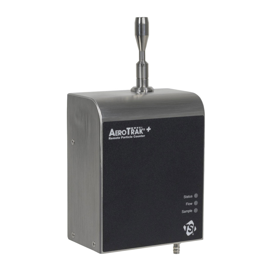
- Page 13 C H A P T E R 1 I n t r o d u c t i o n a n d U n p a c k i n g The AeroTrak ® + Remote Particle Counter (particle counter) is a compact sensor that is appropriate for use in multiple locations in a large clean room or critical environment to continuously monitor a process.
- Page 14 No. Size Part Number Flow Rate Size Channels (um) Channels 7501-22050 2.8 L/min (0.1 cfm) 0.5/5.0 um 7501-22050W* 2.8 L/min (0.1 cfm) 0.5/5.0 um 7501-24100 2.8 L/min (0.1 cfm) 0.5/1.0/5.0/10 um 7501-24100A* 2.8 L/min (0.1 cfm) 0.5/1.0/5.0/10 um 7501-24100W* 2.8 L/min (0.1 cfm) 0.5/1.0/5.0/10 um 7501-25250 2.8 L/min (0.1 cfm)
-
Page 15: Chapter 1 Introduction And Unpacking
No. Size Part Number Flow Rate Size Channels (um) Channels 6501-24250 2.8 L/min (0.1 cfm) 0.5/5.0/10/25 um 6501-24250A* 2.8 L/min (0.1 cfm) 0.5/5.0/10/25 um 6501-24250W* 2.8 L/min (0.1 cfm) 0.5/5.0/10/25 um 6501-25250 2.8 L/min (0.1 cfm) 0.5/1.0/5.0/10/25 um 6501-25250A* 2.8 L/min (0.1 cfm) 0.5/1.0/5.0/10/25 um 6501-25250W* 2.8 L/min (0.1 cfm) -
Page 16: Optional Accessories
Optional Accessories The following tables list optional accessories. If you ordered optional accessories, make certain they have been received and are in working order. All Models Item Description Part/Model Reference Picture Power Supply* PSU-ARWP USB-C Cable 700360 AeroTrak+ Wi-Fi ® Node 700500 *Manufacturer’s Declaration for Korea: This product is intended to be powered by PoE+ or user-supplied 12–24V supply. -
Page 17: L/Min, 1.0 Cfm Models (7310, 7510)
Item Description Part/Model Reference Picture Adapter, Isokinetic Zero 700481 Cap, 0.1 cfm Sample Tubing Superthane Tubing – 1/8 ID 700009 1/4 OD 100 FT Superthane Tubing – 1/8 ID 700010 1/4 OD 1000 FT 28.3 L/min, 1.0 cfm Models (7310, 7510) Item Description Part/Model Ref. - Page 18 Item Description Part/Model Ref. Adapter, Isokinetic Zero 700482 Cap, 1.0 cfm Sample Tubing Superthane Tubing – 1/4 ID 700011 3/8 OD 100 ft Superthane Tubing – 1/4 ID 700012 3/8 OD 1000 ft ® 1–6 AeroTrak + Remote Particle Counter Operation Manual...
-
Page 19: Indicator Leds
C H A P T E R 2 I n s t a l l a t i o n a n d G e t t i n g S t a r t e d This chapter describes the features, connections, and installation of the AeroTrak ®... -
Page 20: Electrical Connections
E l e c t r i c a l C o n n e c t i o n s The state-of-the art AeroTrak+ Remote Particle Counter supports multiple communications and connectivity options. A brief description of each of the connections is listed below. Device Connections •... -
Page 21: Ethernet Connector
Ethernet Connector The particle counter should be connected to a 10/100 Mbps network that supports Power-Over-Ethernet (802.3at PoE+). The green LED indicates that the network is connected. The yellow LED indicates activity on the network cable. The Ethernet LAN connector is a standard 10/100 Mbps 8-Position 8-Contact (8P8C, often called RJ45) modular plug connection that supports Power-Over-Ethernet (802.3at PoE+) devices. -
Page 22: 4-20 Ma Analog Output / Wireless Connector
4-20 mA Analog Output / Wireless Connector This 6-pin connector is used for either a 3-channel 4–20 mA output or to connect to a TSI wireless node, depending on the model used. Two (2) of the analog Terminal Channel Direction outputs are configurable, via Output the Configuration Utility, to... -
Page 23: Installation
I n s t a l l a t i o n Installation of the AeroTrak+ Remote Particle Counter consists of: • Determining the installation location • Mounting the particle counter • Supplying power to the particle counter • Connecting communications from the particle counter to the computer •... -
Page 24: Supplying Power To The Remote Particle Counter
Supplying Power to the Remote Particle Counter The AeroTrak ® + Remote Particle Counter may be powered in one of two ways. For easy installation, the particle counter is designed to work primarily with Power-Over-Ethernet (802.3at PoE+). In some cases; however, this is not possible or practical, so the particle counter can also be powered by the optional TSI Model PSU-ARWP power supply. -
Page 25: Connecting The Remote Particle Counter To A Computer
2. Plug the power supply into a suitable AC outlet. The Status LED on the particle counter should illuminate green. Remote Particle Counter Using DC Power Connecting the Remote Particle Counter to a Computer You can communicate with the particle counter using Modbus TCP over Ethernet. -
Page 26: Connecting Sample Tubing
This requires a vacuum source from a central vacuum system or an external vacuum pump capable of delivering at least 15 inches of Mercury (15 inHg) at the outlet of the counter. The vacuum should be confirmed using an external vacuum gauge measured directly at the outlet of the counter. -
Page 27: Setting The Ip Address Of The Particle Counter
C H A P T E R 3 C o m m u n i c a t i o n s a n d C o n f i g u r a t i o n s Generally, the particle counter will be set up as one of many sensors in a network. -
Page 28: Title Bar
V i e w i n g D e v i c e I n f o r m a t i o n Your device information can be viewed using the Configuration Utility on ® a Windows operating system computer. To connect your Particle Counter with the Configuration Utility, you will need the following: •... -
Page 29: Main Page-Counts Tab
Main Page—Counts Tab Once the unit is powered, launch the Configuration Utility and you will arrive at the Main Page—Counts tab. The following list of items can be viewed on this page: Label Function Sample # Current Sample Number Sample Time (s) Elapsed time in the current sample interval Hold Time (s) Elapsed hold time between sample intervals... - Page 30 Main Page—Instrument Tab The Instrument tab shows device information as described in the table below: Label Function Firmware version Current firmware version programmed on the device Last Cal Date (yyyy-mm-dd) Last date the device was calibrated Nominal Flow (lpm) Nominal flow rate of the device Time that the laser has been on since Laser Run-Time (hrs) manufacture...
- Page 31 Main Page—Communication Tab The Communication tab shows device information for communication purposes as described in the table below: Label Function IP Address/Mask/Gateway Device IP address/mask/gateway MAC Address Device MAC address Modbus Ver Modbus map version. DHCP DHCP enabled or disabled Multicast Address and Port IP address used for multicast broadcasts.
- Page 32 C o n f i g u r i n g t h e P a r t i c l e C o u n t e r In addition to global settings such as IP address, time, date, and location, there are configuration settings that control sampling characteristics.
- Page 33 To enter the Tech Page, you will need to enter the Tech Password. The default password is admin. The Tech Page allows you to configure all device settings under eight tabs: • • Config Instr • • Alarm Data • •...
- Page 34 Tech Page—Configuration (Config) Tab The Configuration page is used to input the sampling parameters and set the system clock. Label Function Sample Interval (s) Sets the length of time for each sample Start Delay (s) Sets the delay time before a sample begins Hold Time (s) Sets the delay time between consecutive samples Run Mode...
- Page 35 Tech Page—Alarm Tab The Alarm tab is used to configure the device alarms based on alarm thresholds for each particle size channel. The alarm threshold is the minimum particle count in each sample interval before an alarm is triggered. Alarms come in two types: Alarm Function Sample Alarm...
- Page 36 Tech Page—Relay Tab The Relay tab allows you to set which conditions enable the relay output, described in the following table. Label Function Channel Sizes (0.3, 0.5, etc.) Toggles to the right of the channel sizes will activate the relay if those channels go into alarm.
- Page 37 Tech Page—Analog Tab The analog tab allows for the configuration of the analog output for models supporting this feature. Label Function Ch A, Ch B Select which size channels to output on analog out channel A and B Ch A Scale, Choose the span scaling of channel A and Ch B Scale channel B.
- Page 38 Tech Page—Instrument (Instr) Tab The Instrument tab is used to configure the device communication settings as described in the table below. This tab also allows you to change Modbus map version, location name and seconds before flow error. Label Function Static IP Address / Sets the IP address, mask, and gateway.
- Page 39 Non-Pump Models Pump Models Communications 3–13...
- Page 40 Tech Page—Data Tab The Data tab is used to retrieve historical sample data by inputting the first record number, the number of consecutive records following the first record, and the filename. Clicking Get Records will output a CSV data file containing sample data from the requested records. Regular data files will retrieve data based on the programmed sample length.
- Page 41 Tech Page—Password (Passwd) Tab The Password tab is used to change the Tech Page password. The default password is admin Save must be pressed for the configurations to be saved to the instrument. Tech Page—Reset Tab This will reset the instrument to its original factory settings. Communications 3–15...
- Page 42 Loading or Saving a Configuration The Configuration Utility allows you to easily save and load the device configuration. This is useful when configuring multiple devices with the same configuration. Use the Up button at the top of the page to load a configuration or use the Down button to save a configuration.
- Page 43 The report page will show a configuration report on all the instruments configurable parameters. Saving a Configuration Report The configuration report can be saved to a PDF file by pressing the up arrow at the top of the report and selecting a name and location for the file.
- Page 44 A b o u t P a g e The About Page is accessed by the menu in the upper left hand of the application. The about page shows the current version of the software application. ® 3–18 AeroTrak + Remote Particle Counter Operation Manual...
- Page 45 C H A P T E R 4 T r o u b l e s h o o t i n g This chapter contains information for troubleshooting common issues ® with the AeroTrak + Remote Particle Counter. Symptom Possible Cause Corrective Action Instrument does not power up -...
- Page 46 (This page intentionally left blank) ® 4–2 AeroTrak + Remote Particle Counter Operation Manual...
- Page 47 TSI Customer Service at 1-800-680-1220 (USA) or (651) 490-2860. International Contacts Service TSI Instruments Singapore Pte Ltd TSI Instrument (Beijing) Co., Ltd. 150 Kampong Ampat Unit 1201, Pan-Pacific Plaza #05-05 KA Centre No.
- Page 48 Technical Support TSI Instruments Singapore Pte Ltd TSI Instrument (Beijing) Co., Ltd. 150 Kampong Ampat Unit 1201, Pan-Pacific Plaza #05-05 KA Centre No. 12 A, Zhongguancun South Avenue Singapore 368324 Haidian District, Beijing, 100181 CHINA Telephone: +65 6595-6388 Fax: +65 6595-6399...
- Page 49 A P P E N D I X A S p e c i f i c a t i o n s All specifications are subject to change without notice. Light Source ......Laser Diode Laser Warranty ...... Five Years Instrument Warranty .....
- Page 50 Included Accessories .... Power and alarm relay connector, operating manual and configuration utility USB Flash Drive Optional Accessories .... Power supply, isokinetic inlets, purge filter, alarm cable, sample tubing, vacuum tubing and mounting bracket S p e c i f i c M o d e l S p e c i f i c a t i o n s 7201 7301 7310...
- Page 51 C o m p l i a n c e Regulatory European Standard EN 61326-1: 2013 Compliance European Standard EN 55011: 2009 + A1: 2010 Testing European Standard EN 61326-1: 2013 Standards Korean Standard KN 11 with RRA Public Notification 2017-19 and RRA Announce 2017-71 Korean Standard KN 61000-6-1 with RRA Public Notification 2017-19 and RRA Announce 2017-71...
- Page 52 D i m e n s i o n a l D i a g r a m M o d e l s 6 2 0 1 , 6 3 0 1 , 6 5 0 1 ® AeroTrak + Remote Particle Counter Operation Manual...
- Page 53 I n d e x contact information, iii installation, 2-1, 2-5 contacting TSI connecting counter to computer, 1-sec alarm, 3-9 email address, iii contacts, 5-1 DC power, 2-6 counting efficiency, A-2 determining location, 2-5 about page, 3-18 counts, 3-3 supplying power, 2-6 screen, 3-18 current flow, 3-3 vacuum tubing, 2-7...
- Page 54 tech page, 3-6 sample hold, 3-3 title bar, 3-2 password, 3-7 sample interval, 3-8, 3-9 trademarks, iv screen, 3-6 sample LED off, 4-1 troubleshooting manual history, ii sample length, 3-3 cleaning, 4-1 manufacturer’s declaration for Korea, sample status, 3-3 critical orifice, 4-1 sample time, 3-3, 3-6 inlet, 4-1 mercury, 2-8...
- Page 56 FCC ID: 2AC7Z-ESP32WROOM32 TSI Incorporated – Visit our website www.tsi.com for more information. Tel: +1 800 680 1220 India Tel: +91 80 67877200 Tel: +44 149 4 459200 China Tel: +86 10 8219 7688 France Tel: +33 1 41 19 21 99 Singapore Tel: +65 6595 6388 Germany...
Need help?
Do you have a question about the AEROTRAK+ 7201 and is the answer not in the manual?
Questions and answers