
Related Manuals for TSI Instruments AeroTrak 9306


Summary of Contents for TSI Instruments AeroTrak 9306
- Page 1 ® AeroTrak Handheld Airborne Particle Counter Model 9306 Operation Manual P/N 6004215, Revision M September 2022 www.tsi.com...
- Page 2 Start Seeing the Benefits of Registering Today! ® ® Thank you for your TSI instrument purchase. Occasionally, TSI releases information on software updates, product enhancements ® and new products. By registering your instrument, TSI will be able to send this important information to you. http://register.tsi.com As part of the registration process, you will be asked for your comments on TSI products and services.
- Page 3 ® AeroTrak Handheld Airborne Particle Counter Model 9306 Operation Manual E-mail address: answers@tsi.com SHIP TO/MAIL TO: TSI Incorporated Website: 500 Cardigan Road http://www.tsi.com Shoreview, MN 55126-3996 INTERNATIONAL Technical Support: U.S. (001 651) 490-2860 Technical Support: Fax: (800) 680-1220/(651) 490-2860 (001 651) 490-3824 Fax: (651) 490-3824...
-
Page 4: Manual History
M a n u a l H i s t o r y The following is a manual history of the AeroTrak ® Handheld Airborne Particle Counter, Model 9306 Operation Manual (P/N 6004215). Revision Date Revision Date July 2010 January 2014 September 2010 February 2016 February 2011... -
Page 5: Warranty
W a r r a n t y Part Number 6004215 / Revision M / September 2022 Copyright ©TSI Incorporated / 2010-2022 / All rights reserved. Address TSI Incorporated / 500 Cardigan Road / Shoreview, MN 55126 / USA E-mail Address answers@tsi.com (For country-specific terms and conditions outside of the USA, please visit www.tsi.com.) Limitation of Warranty... - Page 6 Buyer and all users are deemed to have accepted this LIMITATION OF WARRANTY AND LIABILITY, which contains the complete and exclusive limited warranty of Seller. This LIMITATION OF WARRANTY AND LIABILITY may not be amended, modified or its terms waived, except by writing signed by an Officer of Seller. Service Policy Knowing that inoperative or defective instruments are as detrimental to TSI as they are to our customers, our service policy is designed to give prompt attention to any problems.
-
Page 7: Table Of Contents
C o n t e n t s Manual History .................... ii Warranty ..................... iii Safety Information ..................vii Laser Safety ..................vii Labels ....................viii Description of Caution/Warning Symbols ..........ix Caution ....................ix Warning ....................ix Caution or Warning Symbols ............. ix Getting Help ................... - Page 8 Regional Screen ................. 3-29 Environment Screen ..............3-30 Data Tab ..................3-30 Export Data Screen ..............3-32 Print Data ..................3-35 Reports Tab ................... 3-37 Exclude Samples Form .............. 3-40 Data Integrity Mode ............... 3-41 CHAPTER 4 Data Handling ..............4-1 USB Data Download ................
-
Page 9: Safety Information
S a f e t y I n f o r m a t i o n This section gives instructions to promote safe and proper handling of the ® AeroTrak Handheld Airborne Particle Counters. I M P O R T A N T N O T I C E There are no user-serviceable parts inside the instrument. -
Page 10: Labels
L a b e l s Advisory labels and identification labels are attached to the outside of the particle counter housing and to the optics housing on the inside of the instrument. 1. Serial number label (back panel) 2. Laser radiation label (internal) 3. -
Page 11: Description Of Caution/Warning Symbols
D e s c r i p t i o n o f C a u t i o n / W a r n i n g S y m b o l s Appropriate caution/warning statements are used throughout the manual and on the instrument that require you to take cautionary measures when working with the instrument. -
Page 12: Getting Help
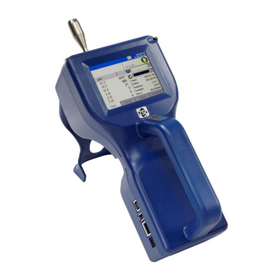
G e t t i n g H e l p To obtain assistance with this product or to submit suggestions, please contact Customer Service: TSI Incorporated 500 Cardigan Road Shoreview, MN 55126 U.S.A. Fax: (651) 490-3824 (USA) Fax: 001 651 490 3824 (International) Telephone: 1-800-680-1220 (USA) or (651) 490-2860 International: 001 651 490 2811 E-mail Address:... - Page 13 C H A P T E R 1 I n t r o d u c t i o n a n d U n p a c k i n g The AeroTrak ® Model 9306 Airborne Particle Counter (particle counter) is a lightweight, handheld particle counter with a touch-screen interface.
- Page 14 U n p a c k i n g t h e A e r o T r a k ® H a n d h e l d A i r b o r n e P a r t i c l e C o u n t e r Carefully unpack the AeroTrak ®...
-
Page 15: Chapter 1 Introduction And Unpacking
Qty. Item Description Part/Model Reference Picture ® Operation Manual 6004215 Available on TSI website: tsi.com. Quick Start Guide 6004216 Calibration certificate Introduction and Unpacking... -
Page 16: Optional Accessories
Optional Accessories The following photos and table list optional accessories. If you ordered optional accessories, make certain they have been received and are in working order. ® Model 9306 AeroTrak Airborne Particle Counter Optional Accessories Item Description Part/Model Reference Picture External battery charger with 700025 AC adapter and power cord... -
Page 17: Instrument Description
C H A P T E R 2 G e t t i n g S t a r t e d This chapter provides information to help you use the Model 9306 AeroTrak ® Handheld Airborne Particle Counter including: •... -
Page 18: Using The Instrument Stand And Stylus
U s i n g t h e I n s t r u m e n t S t a n d a n d S t y l u s The Model 9306 is equipped with an integral instrument support stand. -
Page 19: Providing Power
P r o v i d i n g P o w e r The Model 9306 may be powered using a rechargeable lithium-ion battery, or through an AC power cord. NOTICES • When using AC power, the battery (if installed) charges when the instrument is on, but not while actively sampling. -
Page 20: To Use Ac Power
To Use AC Power 1. Connect the AC power adapter to the power cord. 2. Insert the AC power adapter into the side of the Model 9306. 3. Connect the power cord to an outlet. 4. Press the on/off button (located on the front of the instrument handle). -
Page 21: Installing An Isokinetic Inlet
I n s t a l l i n g a n I s o k i n e t i c I n l e t The Isokinetic inlet smoothly accelerates air into the inlet of the instrument. To install, simply thread the inlet directly onto the inlet nozzle until finger tight. - Page 22 (This page intentionally left blank) ® AeroTrak Handheld Airborne Particle Counter...
- Page 23 C H A P T E R 3 O p e r a t i o n ® The Model 9306 AeroTrak Handheld Airborne Particle Counter is controlled using a touch screen display. NOTICE Use the plastic stylus or your finger tip. DO NOT use sharp objects (such as a pen point) that may damage the screen overlay.
-
Page 24: Screen Layout And Functionality
S c r e e n L a y o u t a n d F u n c t i o n a l i t y There are four main screens (tabs): • Main • Setup • Data •... -
Page 25: Main Tab
Main Tab The Main tab is the default screen. The left side of the screen summarizes the concentrations for the currently selected location. Tap on the size and count portion of the screen to enable Zoomed Data Screen (see Setup Tab). - Page 26 Icon Description Indicates that TrakPro™ Lite Secure software is interfacing with the ® AeroTrak particle counter. The front panel GUI is inoperable when the software is operational. Once the software is exited, normal front panel operation will resume. Press and hold the (Zone) icon to display a summary of information for the current Zone.
- Page 27 Field Description Displays the Zone where the sample is being taken by the instrument. Press the icon to display (Zone) a summary of information for the Zone. This drop-down box allows selection of a preconfigured Location to associate the sampled (Location) data to.
- Page 28 ™ A USB 1D barcode scanner can be used (Zebra LS2208 works well) to select an existing Zone and Location pair in the list boxes on the Main page, if the barcodes use the format ZoneName:LocationName (i.e., the zone name followed by a colon followed by the location name). The barcode can then be scanned and the specified zone and location will be automatically selected in the list boxes.
-
Page 29: Zoomed Data Screen
Zoomed Data Screen The Zoomed Data screen is entered by touching in the size and count part of the main tab display. The bottom portion of the screen summarizes the concentrations for the currently selected location. Tap the size and count portion of the display to switch back to the Main tab display. -
Page 30: Setup Tab
Setup Tab The Setup tab provides access to the following: Identify and save the location information associated Zones Setup with collected samples. Recipes Setup Save a group of settings (a Recipe) that you use over and over so you do not have to reset individual settings. -
Page 31: Zone Setup Screen
Zone Setup Screen ”Zones” are a convenient way to group sample data for printing and export, and are required for creating standards-based classification reports. A Zone contains 1 or more “Locations”; this is modeled after cleanroom standards that prescribe the classification of a zone (or room) by taking samples at various locations within the zone. - Page 32 To Delete A Zone To delete a zone from the configuration screen, select (highlight) the zone name and press Delete. A verification message “Are you sure you want to delete this Zone?” appears. Press Yes to delete the zone. A zone that has data associated with it cannot be deleted. The data associated with the zone must be deleted from the instrument before the zone can be deleted.
- Page 33 3. Enter names for each location in the zone and then press Add after entering each. The name will be added to the box on the left-side of the screen. 4. Press the Recipe tab. The Recipe screen is displayed with a default recipe in the “Selected Recipe”...
- Page 34 3. The Definition screen for each zone provides the same information as displayed on the main Zone Configuration screen with the addition of “Largest Particle Size to Consider” field. 4. The Locations screen displays the locations within the selected zone. You can add, rename, or remove a location from the zone. You can also move the location name up or down in the list.
- Page 35 6. The Recipe screen displays the recipe in use for the selected zone and information relevant to that recipe. You can select a different recipe for the zone or you can create a new recipe or edit an existing recipe. (For information about recipes see the Recipes section in Setup.)
-
Page 36: Recipes Setup Screen
Recipes Setup Screen Use the Recipes setup screen to review recipes, add or delete recipes, and edit recipes. You cannot delete the “Default” recipe. A recipe that has samples cannot be deleted. NOTICE The Delete button will be grayed out and unavailable if the recipe has samples. - Page 37 3. Select the Count Mode: options are Automatic, Manual, and Beep as described below. Field Description Automatic If this mode is selected, the particle counter starts counting in automatic mode when the start button is pressed according to the settings on the Recipes Timing Screen.
- Page 38 5. Press the Timing tab to enter or edit start delay times, sample time, hold time, etc. 6. To make changes to the timing settings, highlight the value to change (hours, minutes, seconds, etc.) and use the on-screen keypad to change the value.
- Page 39 Field Description Start Delay Start Delay indicates the instrument delay before starting a sample. N O T I C E It takes approximately 10 seconds for the pump to reach the flow set point; taking a measurement before the pump is properly functioning may result in a data and flow error.
- Page 40 To acknowledge the alarm and silence the buzzer, tap the alarm icon NOTICES • In Differential modes (Δ), disabling one or more channels will disable all threshold alarms. Other alarms are not affected. • While in beep mode, a threshold of 0 will not trigger an audible alarm even if Alarm is enabled.
-
Page 41: System Setup Screen
System Setup Screen Use the System Setup screen to select or change: • Power On Password • Print Setup • Setup Password • Print Schedule • Configuration parameters • Clear Samples Change Power On Password Screen If a Power On password is set, a password is required before the instrument will operate. - Page 42 Tap the Power On password icon to display the on-screen keyboard and enter the required information. Field Description Old Password Enter your existing password (if one has already been set) or leave blank. New Password Enter a new password. The password can be any length and use any characters.
-
Page 43: Change Setup Password Screen
Change Setup Password Screen If a Setup password is set, a password must be entered to change instruments settings. On the main screen, selecting the Setup tab at the bottom will display a password screen. If a Setup password has been previously set, that password must be entered before choosing a new Setup password. -
Page 44: Configuration Screen
Configuration Screen Use the Configuration screens to set configuration parameters. Press OK when finished. Field Description and on Zoom When selected, tapping the left side of Main tab on the instrument’s screen will zoom (enlarge) both cumulative (Σ) and differential (Δ) counts (allow the screen a moment to update). -
Page 45: Print Setup Screen
Print Setup Screen A hard copy of a sample set or statistics can be printed from the instrument using an optional thermal printer. Use this screen to set print parameters. Press OK when finished. These selections will apply when printing automatically or when printing from the Data tab page. Field Description Serial Number... -
Page 46: Print Schedule Screen
Print Schedule Screen Use the Print Schedule screen to schedule automatic printing. Choose to either print when an alarm occurs or whenever a sample is complete. “English Only Printing” will print reports in English even when the selected language is not English. The default zones and locations will print in English. -
Page 47: Clear Samples Screen
Clear Samples Screen Use the Clear Samples screen to clear all samples from the internal database. Select Yes to clear all samples. Select No to return to the System Setup screen. C A U T I O N WHEN “YES” IS SELECTED ON THE CLEAR SAMPLES SCREEN, ALL SAMPLE... -
Page 48: Device Setup Screen
Device Setup Screen Use the Device Setup screen to access screens that let you set or change the date and time, calibrate the touch screen, set up communications, and set regional features. Date and Time Screen Use the Date and Time screen to set the current date, time, and the time format. -
Page 49: Display Screen
Display Screen Use the Display screen to calibrate the touch screen. Field Description Screen Alignment Press this item to reset the screen alignment. Follow the directions on the alignment screen. N O T I C E The touch screen display is aligned at the factory and typically will stay aligned for the life of the instrument. -
Page 50: Communications Screen
Communications Screen Use the Communications screen to configure the following: • IP address • Subnet Mask • Default Gateway (to which the instrument belongs) Addresses can be entered using the arrows or by selecting a field and using the on-screen keypad. Field Description IP Address... -
Page 51: Regional Screen
Regional Screen Use the Regional screen to set the language for the display dialogs and the regional format for numbers. Field Description Language Select the language for the display; options are German, English, Spanish, French, Italian, Chinese (simplified), and Japanese. Select the format that is commonly used to display real Formats numbers and the date and time in your region. -
Page 52: Environment Screen
Environment Screen When a temperature, humidity, or air flow velocity sensor is connected to the instrument, use the Environment screen to set the units that will display on the Main and Data Tabs, and in the printouts. Field Description Display temperature in degrees Fahrenheit. °... - Page 53 NOTICE Counts displayed on the data tab concentration may have slight rounding errors when comparing all channels to values with selected channels enabled. The method for calculating concentration is to sum the raw counts for each location, calculate concentration from sample volume and then round.
-
Page 54: Export Data Screen
Export Data Screen Use the Export Data screen to export sample data to a USB flash drive. Select the name of the file and range of data to export. Data is downloaded into an XML file that can be opened with commonly used spreadsheet programs. - Page 55 2. Select a file from the list and click: a. “Export” to overwrite an existing file selected from the file list. b. “Export As…” to enter a filename. Then select OK. 3. Select Sample Data by Zone or by Sample index range with option of limiting samples to a date range.
- Page 56 4. To select data for export by zone, move a desired zone to the box on the right to select it. To select data by sample index range instead, tap the Select by Record button at the bottom. 5. To select data for export by range of sample Index, tap Select Range radio button and then select the lower and upper sample index numbers.
-
Page 57: Print Data
Print Data The print button allows a range of sample data to be printed using the optional printer. • The “Print by Record” form or the “Print by Zone” form can be used. Both forms provide the option to limit data selection to a date range. - Page 58 2. Move a zone to the box on the right to select it for printing. 3. Alternatively, print samples within a date range by checking Use Start Date and/or Use End Date checkboxes and selecting the dates. 4. To the Select by Record button at the bottom to select data by range or sample index.
-
Page 59: Reports Tab
9. The print data screen shows progress on the current selected range of sample data. Press the Cancel Printing button to cancel the rest of the print job. Printouts that include sample data will identify the samples as “Sample X of Y” where X is the current sample in the set (not the sample ID for the sample) and Y is the total number of samples in a set being printed (not the total number of samples on the instrument). - Page 60 2. Check the “Recipe” checkbox to include recipe details on the report. 3. When you press the Generate button, you are given the option to enter a title for the report. 4. Enter a title or leave the text box blank. 5.
- Page 61 6. Report will show the title you provided. Field Description Zone Select the zone from the drop-down list. Standard Select the standard from the drop-down list. Class Select the class from the drop-down list. Use Start Date Exclude samples collected before a specified date. Use End Date Exclude samples collected after a specified date.
-
Page 62: Exclude Samples Form
Exclude Samples Form The “Exclude Samples” form shown below is displayed when you click the Exclude Samples button. 1. Enter ID number of sample to exclude in the left column and ID number of sample to replace it (if required by standard) in right column. -
Page 63: Data Integrity Mode
Data Integrity Mode Data Integrity Mode allows the unit to be locked down to ensure the sampling data cannot be modified. When in this mode, all printing and data exporting is prohibited. Data Integrity Mode is designed to be used in conjunction with TrakPro™ Lite Secure software. - Page 64 The unlock icon on the main page indicates the instrument is in data integrity mode and unlocked. The user icon indicates which user has the instrument unlocked in data integrity mode. Now that the instrument is unlocked for sampling, a zone and location can be selected.
- Page 65 After a zone and location has been selected and password entered, the green start sample icon will appear and sample(s) can be taken. After a sample is complete, the instrument defaults to no zone and no location; the start sample icon will no longer be available. A zone and location will need to be selected to enable the start sample icon.
- Page 66 (This page intentionally left blank) ® 3-44 AeroTrak Handheld Airborne Particle Counter...
-
Page 67: Usb Data Download
C H A P T E R 4 D a t a H a n d l i n g U S B D a t a D o w n l o a d The Model 9306 AeroTrak ® Handheld Airborne Particle Counter is equipped... -
Page 68: Installing Software
I n s t a l l i n g S o f t w a r e ™ 1. The TrakPro Lite Secure Data Transfer utility and user manuals are available on TSI’s website: tsi.com/software/. 2. To install the communications software and drivers, follow the on- screen instructions. -
Page 69: Maintenance Schedule
C H A P T E R 5 M a i n t e n a n c e The chapter contains maintenance and troubleshooting solutions for the Model 9306 AeroTrak ® Handheld Airborne Particle Counter. NOTICE There are no user-serviceable parts inside this instrument. Opening the ®... - Page 70 (This page intentionally left blank) ® AeroTrak Handheld Airborne Particle Counter...
- Page 71 C H A P T E R 6 T r o u b l e s h o o t i n g Symptom Possible Cause Corrective Action Counts are too low. Instrument is being operated outside Operate instrument within temperature or relative humidity specifications.
- Page 72 Symptom Possible Cause Corrective Action Battery does not charge. The unit must be turned on but not in Turn on unit. sampling mode for the battery to charge. The battery will only charge if the unit is turned on but is not actively taking a sample.
-
Page 73: Technical Contacts
® tsi.com/service, or contact TSI Customer Service at 1-800-680-1220 (USA) or (651) 490-2860. International Contacts Service TSI Instruments Singapore Pte Ltd 150 Kampong Ampat #05-05 KA Centre Singapore 368324 Telephone: +65 6595-6388 Fax:... -
Page 74: Technical Support
Cressex Business Park High Wycombe, Buckinghamshire HP12 3ST UNITED KINGDOM Telephone: +44 (0) 149 4 459200 E-mail: tsiuk@tsi.com Technical Support TSI Instruments Singapore Pte Ltd 150 Kampong Ampat #05-05 KA Centre Singapore 368324 Telephone: +65 6595-6388 Fax: +65 6595-6399 E-mail: tsi-singapore@tsi.com... -
Page 75: Returning The Aerotrak Handheld Airborne Particle Counter For Service
® R e t u r n i n g t h e A e r o T r a k H a n d h e l d A i r b o r n e P a r t i c l e C o u n t e r f o r S e r v i c e and complete the on-line “Service Visit our website at tsi.com/service... - Page 76 (This page intentionally left blank) ® AeroTrak Handheld Airborne Particle Counter...
- Page 77 A P P E N D I X A S p e c i f i c a t i o n s All specifications meet or exceed ISO 21501-4 and JIS B9921. They are subject to change without notice. Specification Description Size Range ........
-
Page 78: Temperature/Rh Probe (700084) Specifications (Optional Accessory
Specification Description External Surface ....... High impact injection molded plastic AC Power (power to AC adapter) ... 110 to 240 VAC 50 to 60 Hz Universal in-line power supply DC Power (power to instrument) ..12 VDC @ 2.5 A Battery .......... -
Page 79: Compliance
C o m p l i a n c e CE Marking ..EN61326 / EN 55011, Class BA: Radiated Emissions EN61326 / EN 55011, Class BA: Conducted Emissions EN61000-3-2: Harmonics EN61000-3-3: Voltage Fluctuations EN61000-4-2: Electrostatic Discharge Immunity EN61000-4-3: Electromagnetic Field Immunity EN61000-4-4: Burst Immunity EN61000-4-6: Conducted PS Immunity EN61000-4-5: Surge Immunity... - Page 80 (This page intentionally left blank) ® AeroTrak Handheld Airborne Particle Counter...
- Page 82 TSI Incorporated – Visit our website www.tsi.com for more information. Tel: +1 800 680 1220 India Tel: +91 80 67877200 Tel: +44 149 4 459200 China Tel: +86 10 8219 7688 France Tel: +33 1 41 19 21 99 Singapore Tel: +65 6595 6388 Germany Tel: +49 241 523030...
Need help?
Do you have a question about the AeroTrak 9306 and is the answer not in the manual?
Questions and answers
TSI PC password mone porse na
To reset the password for the TSI Instruments AeroTrak 9306, you need to contact TSI technical support. It is difficult to reset the password without their assistance.
This answer is automatically generated