TSI Instruments 9310 Operation Manuals
Aerotrak series portable airborne particle counter
Hide thumbs
Also See for 9310:
- Operation manual (91 pages) ,
- Quick start manual (4 pages) ,
- Service manual (84 pages)

Related Manuals for TSI Instruments 9310


Summary of Contents for TSI Instruments 9310
- Page 1 P o r t a b l e P a r t i c l e C o u n t e r s Portable ™ Airborne Particle Counter Model 9310/9350/9510/9550/9500 Operation Manual P/N 6004217, Revision F May 2011...
- Page 3 Portable ™ Airborne Particle Counter Model 9310/9350/9510/9550/9500 Operation Manual P/N 6004217, Revision F May 2011 SHIP TO/MAIL TO: E-mail address: TSI Incorporated aerotrak@tsi.com 500 Cardigan Road Website: Shoreview, MN 55126-3996 http://www.tsi.com U.S. INTERNATIONAL Technical Support: Technical Support: (800) 874-2811/(651) 490-2811...
-
Page 4: Manual History
M a n u a l H i s t o r y The following is a manual history of the A Portable ™ Airborne Particle Counter, Model 9310, 9510, 9350, 9550, 9500 Operation Manual (P/N 6004217). Revision Date July 2010... -
Page 5: Warranty
W a r r a n t y Part Number 6004217 / Revision F / May 2011 Copyright ©TSI Incorporated / 2010-2011 / All rights reserved. TSI Incorporated / 500 Cardigan Road / Shoreview, MN 55126 / USA Address aerotrak@tsi.com E-mail Address Limitation of Warranty Seller warrants the goods sold hereunder, under normal use and service as described in... -
Page 7: Table Of Contents
C o n t e n t s Manual History .................... ii Warranty ..................... iii Safety Information ..................vii Laser Safety ..................vii Labels ....................viii Description of Caution/Warning Symbols ..........ix Caution ....................ix Warning ....................ix Caution or Warning Symbols ............. ix Getting Help ................... - Page 8 CHAPTER 4 Data Handling ..............4-1 USB Data Download ................4-1 USB Computer Communication ............4-1 Installing Software ................4-2 Ethernet Communications ..............4-2 CHAPTER 5 Maintenance ............... 5-1 Maintenance Schedule ................ 5-1 Zero Check ..................5-1 Cleaning the Instrument Inlet .............. 5-2 Cleaning the Instrument Enclosure .............
-
Page 9: Safety Information
S a f e t y I n f o r m a t i o n This section gives instructions to promote safe and proper handling of the A Portable Airborne Particle Counter. ™ I M P O R T A N T There are no user-serviceable parts inside the instrument. -
Page 10: Labels
L a b e l s Advisory labels and identification labels are attached to the outside of the particle counter housing and to the optics housing on the inside of the instrument. 1. Serial number label (back panel) 2. Laser radiation label DANGER! (internal) VISIBLE LASER RADIATION WHEN... -
Page 11: Description Of Caution/Warning Symbols
D e s c r i p t i o n o f C a u t i o n / W a r n i n g S y m b o l s Appropriate caution/warning statements are used throughout the manual and on the instrument that require you to take cautionary measures when working with the instrument. -
Page 12: Getting Help
G e t t i n g H e l p To obtain assistance with this product or to submit suggestions, please contact Customer Service: TSI Incorporated 500 Cardigan Road Shoreview, MN 55126 U.S.A. Fax: (651) 490-3824 (USA) Fax: 001 651 490 3824 (International) Telephone: 1-800-874-2811 (USA) or (651) 490-2811 International: 001 651 490 2811 E-mail Address:... - Page 13 Data Download Software included with the device. Each model is also available with an “N” suffix to indicate a “No Printer” option. Model Size Range Flow Rate 9310-02 0.3, 0.5, 1.0, 3.0, 5.0, 10.0 μm 28.3 L/min (1 CFM ) 9510-02 0.5, 0.7, 1.0, 3.0, 5.0, 10.0 μm 28.3 L/min (1 CFM )
- Page 14 ™ Portable Airborne Particle Counter Parts List Qty. Item Description Part/Model Reference Picture 9310-02 Airborne Particle 9510-02 Counter 9350-02 9350-03 9550-02 9500-01 Barb Inlet Fitting 700061 (28.3 and (installed) 50 L/min models) 700090 (100 L/min models) Power Supply 801692 24 VDC 3.0A...
-
Page 15: Chapter 1 Introduction And Unpacking
Qty. Item Description Part/Model Reference Picture Computer cable 700033 (2 m), USB A to B Stylus HEPA zero filter 700015 (Filters for assembly 28.3, 50 and 100 L/min models) 700067 (Metal adapter for the 28.3 and 50 L/min model) 700098 (Metal Adapter for the 100 L/min Model) ™... -
Page 16: Optional Accessories
Optional Accessories The following photos and table list optional accessories. If you ordered optional accessories, make certain they have been received and are in working order. ™ Portable Airborne Particle Counter Optional Accessories Item Description Part/Model Reference Picture Stainless Steel Isokinetic 700069 Probe (used with tubing) (28.3 L/min) - Page 17 Item Description Part/Model Reference Picture Velocity/Temperature/ 964 (Straight) Relative Humidity Probe 966 (Articulated) Velocity/Temperature 960 (Straight) Probe 962 (Articulated) Temperature/RH Probe 700097 with Cable Carry Case 700086 Heavy Duty Carry Case 700087 (rolling case) ™ Lite Secure 7001888 (optional CD for 21 CFR Part 11 accessory) compliant data downloading...
- Page 18 (This page intentionally left blank) ™ Portable Airborne Particle Counter...
- Page 19 C H A P T E R 2 G e t t i n g S t a r t e d This chapter describes the features, connections, and installation of the A Portable Airborne Particle Counter (particle ™ counter). It includes: •...
- Page 20 I n s t r u m e n t D e s c r i p t i o n The A Portable Airborne Particle Counter has many ™ features to make measurements convenient. The power switch is located on the front panel in the lower-left. A power LED indicates when the instrument is powered up.
-
Page 21: Chapter 2 Getting Started
Description Function Alarm This connector provides two pins for a contact closure to control an external alarm. The contact closure is normally open and rated for 0 to 60 V AC/DC at 1.5A peak, 0.5A continuous. The “alarm out” connection is rated for 60 V insulation. The contact is closed under alarm conditions determined by the programming of the device. -
Page 22: Providing Power
P r o v i d i n g P o w e r These particle counters may be powered using rechargeable lithium- ion batteries (from one to four) or through an AC power cord. Notes: • When using AC power, the battery (if installed) charges when the instrument is on, while actively sampling (trickle charging), and when the power is put in standby—charge battery mode. -
Page 23: To Install The Lithium-Ion Battery
To Install the Lithium-Ion Battery 1. Remove the battery door on the back of the instrument by turning the two thumbscrews counterclockwise. 2. One battery is provided for the 28.3 and 50 L/min models, but up to two batteries can be used to extend the run time. Two batteries are provided for the 100 L/min model (Model 9500) and both must be present for the unit to operate on batteries. -
Page 24: To Use Ac Power
To Use AC Power Connect the country-appropriate power cord to the external power supply. Next connect the 24 VDC connector to the socket in the particle counter and then connect the other end to an AC outlet. W A R N I N G The instrument turns on automatically when the AC power supply is plugged in. -
Page 25: Using The Integral Thermal Printer
U s i n g t h e I n t e g r a l T h e r m a l P r i n t e r The side-mounted integral thermal printer is standard on most models to print manually, automatically after each test is completed, or whenever the alarm function is activated (see Print Setup Screen... -
Page 26: Using Peripherals
The printer has a feed and stop button as well as an LED indicating that the printer is ready. The feed button can be held down at the end of a print to allow enough space to tear off the paper. -
Page 27: Filter Scanner
W A R N I N G When connected to the alarm out connector, you must use safety certified equipment and/or power sources. Filter Scanner This connector is used with the optional TSI Electronic Filter Scanner (TSI P/N 700103). Plugging in the connector from the Electronic Filter Scanner allows you to start and stop a sample from the probe head. -
Page 28: Alarm
Alarm This connector is used to communicate the alarm status of the instrument. When the instrument is in flow or laser alarm, the dry relay will close. The mating connector and ferrite is provided. The user must supply the wiring. Install the clamp-on ferrite so that it is within 1 inch of the connector as shown. -
Page 29: Using Communications Ports
U s i n g C o m m u n i c a t i o n s P o r t s USB B (to Ethernet computer) Port USB B The standard USB B connector is used to connect the instrument to a computer running TSI T Lite software for data ™... -
Page 30: Performing A Zero Check
P e r f o r m i n g a Z e r o C h e c k A zero check should be performed according to application requirements. It should also be performed before conducting any important testing or certification. To Perform a Zero Check 1. -
Page 31: Using An Isokinetic Probe
Note: If the instrument does not go to zero (1 particle in 5 minutes is considered zero), refer to Chapter 6, Troubleshooting, for additional information. 6. Remove the zero filter assembly and put the isokinetic inlet back on the instrument is now ready for operation. U s i n g a n I s o k i n e t i c P r o b e The isokinetic probe smoothly accelerates air into the inlet of the instrument. -
Page 32: Using An Isokinetic Inlet
U s i n g a n I s o k i n e t i c I n l e t The isokinetic inlet is similar to the isokinetic probe but it mounts directly on the instrument inlet. To install, remove the barbed inlet by unscrewing and simply thread the inlet directly onto the threaded inlet until finger tight. -
Page 33: Chapter 3 Operation
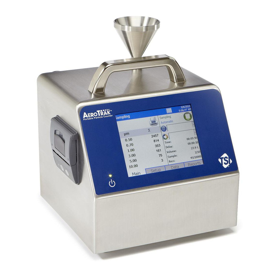
C H A P T E R 3 O p e r a t i o n The A Portable Airborne Particle Counter is controlled ™ using a touch screen display. Use the plastic stylus or your finger tip. DO NOT use sharp objects (such as a pen point) that may damage the screen overlay. -
Page 34: Screen Layout And Functionality
S c r e e n L a y o u t a n d F u n c t i o n a l i t y There are four main screens (tabs): Main, Setup, Data, and Reports. The operation of each of these screens, the information displayed on them, and the operations you can perform from each are described in the remainder of this chapter. - Page 35 The status bar at the top of the screen shows the current time and date settings (see the Setup Tab) and indicates: Icon Description Laser requires service. Sufficient flow through the instrument Note: During Start Delay (Delay) and Hold Times (Hold), this is only an indicator of flow On.
- Page 36 Field Description Location describes where a sample is being taken. (Location) This dropdown box displays information about saved locations. The chosen location displayed on the Main screen is the location associated with the sample to be taken. A recipe is the group of settings that are used for a sample.
- Page 37 Zoomed Data Screen The Zoomed Data screen is entered by touching in the size and count part of the main tab display. The bottom portion of the screen summarizes the concentrations for the currently selected location. Tap the size and count portion of the display to switch back to the Main Tab display.
-
Page 38: Setup Tab
Setup Tab The setup tab provides access to the following: Sampling Setup Set up Particle Channels, Sample Timing, Particle Channel Alarms, Sample Count Mode, Count Units, and Environment display settings. Locations Setup Identify and save the location information associated with collected samples. Recipe Setup Save a group of settings (a recipe) that you use over and over so you don’t have to reset individual... - Page 39 System Setup Screen From the System Setup screen you can select (or change) the power on password, set up a password, select system configuration parameters, select print settings, schedule printing and clear samples. Operation...
- Page 40 Change Power On Password Screen If a Power On password has been previously set, you must enter that password before being allowed to change the Power On password. If a Power On password is set, then on instrument startup a password screen will ask for the password before the instrument can be used.
- Page 41 Change Setup Password Screen If a Setup password has been previously set, you must enter that password before being allowed to change the Setup password. If a Setup password is set, clicking on the setup tab at the bottom of the main screen brings up a password screen.
- Page 42 Configuration Screen Use this screen to set configuration parameters. Press OK when finished. Field Description ∆ and Σ on Zoom Select to zoom in on both cumulative (Σ) and differential (Δ) counts on the Main Tab. To zoom the Main Tab, select on the left side of the Main Tab (it takes a moment for the screen to update.) Click on the screen again to return to normal view.
- Page 43 Print Setup Screen A hard copy of a sample set or statistics can be printed from the instrument using an optional thermal printer. Use this screen to set print parameters. Press OK when finished. Field Description Serial Number Indicates that the serial number of the particle counter used to collect the data will be printed.
- Page 44 Print Schedule Screen Use this screen to schedule automatic printing. Choose to either print when an alarm occurs or print whenever a sample is complete. Field Description Automatic Printing Enables automatic printing. On Sample Print data whenever a sample completes. On Alarm Print data when an alarm condition occurs.
- Page 45 Device Setup Screen Use this screen to access screens that let you set or change the date and time, set visual parameters of the display, set up communications, set regional features, and get system information such as software version, etc. Date and Time Screen This screen lets you set the current date and time and set the date format.
- Page 46 Display Screen This screen lets you set or change visual parameters Field Description Screen Alignment Press this item to reset the screen alignment, and follow the directions on the alignment screen. Information Screen This screen lets you view the system’s model, serial number, copyright, manufacture date, calibration date, next calibration date, firmware version, USB IP address and date and time format.
- Page 47 Communications Screen This screen lets you configure the IP address, subnet, and default gateway to which the instrument belongs. Field Description IP Address The numerical identification (logical address) that is assigned to this device when participating in a computer network utilizing the Internet Protocol for communication between its nodes.
- Page 48 Regional Screen This screen lets you set the language in which the on-screen dialog is displayed and your regional format for numbers. Field Description Select the language in which you want on-screen dialog Language displayed; options are German, English, Spanish, French, Italian, Chinese (simplified), and Japanese.
- Page 49 Channels Screen This screen lets you choose the channels that are enabled. Press OK when finished. Field Description Enable Select the channels you want to view on the main display. Size Channel size boundaries are shown. These are fixed and cannot be changed. Operation 3-17...
- Page 50 Sample Timing Screen This screen lets you select parameters for sampling. Use the up and down arrows or the on-screen keyboard to change or enter information. These parameters are only valid when the particle counter is running in Automatic mode. Press OK when finished. Field Description Sample...
- Page 51 Alarms Screen Use this screen to enable and set the alarm threshold for each channel. Press OK when finished. Field Description Select the channels on which you want to enable Enable alarms. Threshold To change the threshold for any channel, click the up and down arrows for that channel or use the on- screen keyboard to change its value.
- Page 52 Count Mode Screen Use this screen to set the sample count mode. Press OK when finished. Field Description Automatic If you select this mode, the particle counter starts counting in automatic mode when you press the start button according to the settings on the Sample Timing Screen.
- Page 53 Count Units Screen This screen lets you set the way in which particle concentration information is displayed. Field Description Differential Select to display particle concentration as a differential Δ (the total number of counts is the number of particles between bin sizes). Cumulative Select to display particle concentration as cumulative Σ...
- Page 54 Environment Screen Use this screen to set the units for temperature, which is displayed on the Main and Data Tabs, and the printouts when a humidity and temperature probe is hooked up to the instrument. Field Description °F Display temperature in degrees Fahrenheit. °C Display temperature in degrees Celsius.
- Page 55 Locations Screen Associating collected samples with labeled locations can help keep your data organized. The particle counter allows you to create up to 250 labeled locations (up to 10 characters in length). Use this screen to add, remove, or modify a location names to the list of locations.
- Page 56 To add a location, click on the blank selection at the top of the list and click on the Add… button. In the “Add Location” screen click in the edit box in the middle and use the on-screen keyboard to add a location name.
- Page 57 Field Description Save If you select a name in the box (highlighted) when you select Save, the recipe is saved over the selected file name (no dialog pops up asking for a file name). If no name is selected (highlighted), then you are asked for a file name and no Recipe name is currently selected.
-
Page 58: Data Tab
Data Tab The Data tab lets you preview data that has been collected. Use the scroll bar (slide) on the right to scroll though the records. The record number is displayed at the bottom of the tab. As each record displays, its data and relevant parameters are displayed. Field Description #, ft... - Page 59 Export Data Screen The export button lets you export sample data to a flash drive. You will be able to select the name of the file and range of data to export. Field Description Export If you select a name in the box (highlighted), the data is exported to the selected file name (no dialog pops up asking for a file name).
- Page 60 Print Data The print button allows a range of sample data to be printed using the internal printer. 3-28 ™ Portable Airborne Particle Counter...
-
Page 61: Reports Tab
The print data screen will show progress on the current selected range of sample data to be printed. Press the Cancel Printing button to cancel the rest of the print job. You will have a chance to preview the printout before actually printing to paper. - Page 62 The standard reports are shown below: 3-30 ™ Portable Airborne Particle Counter...
- Page 63 Field Description Room Area Displays the area of the room in ft or m Class Level Depends on the report definition, see below. Air Flow Displays the airflow characteristics of the room. Room Status Displays the status of the room (see Room Definition Screen below).
- Page 64 Room Definition Screen Use this screen to define specific values for the room. Press OK when finished. Field Description Room Status Select the room status: As Built, At Rest, or Operational. Air Flow Select the air flow: Unidirectional or Non- unidirectional.
- Page 65 Generate Screens When you press the Generate icon from any of the report screen, the following screen is displayed to let you select either all records or a range of records to generate the report. After selecting the desired records, press the Channels… button. After you select Channels…...
- Page 66 The generated report is displayed on the screen and may be viewed there. It can also be printed using the optional 8930 printer (must be attached) by pressing the Print button. 3-34 ™ Portable Airborne Particle Counter...
-
Page 67: Chapter 4 Data Handling
C H A P T E R 4 D a t a H a n d l i n g There are three basic ways to get data from the A ™ Portable Airborne Particle Counter: 1. Data download to a USB Flash Drive. 2. -
Page 68: Installing Software
Installing Software See the T Lite Software (version 2.2 or later) User’s Guide ™ (P/N 6002796) on CD (P/N 7001384) for installation instructions. E t h e r n e t C o m m u n i c a t i o n s An Ethernet port is provided for use with TSI Facility Monitoring Software (FMS). -
Page 69: Chapter 5 Maintenance
C H A P T E R 5 M a i n t e n a n c e The chapter contains maintenance and troubleshooting solutions for the Model 9310/9510/9350/9550/9500 A Portable ™ Airborne Particle Counters. N o t e There are no user-serviceable parts inside this instrument. -
Page 70: Cleaning The Instrument Inlet
C l e a n i n g t h e I n s t r u m e n t I n l e t The instrument’s inlet should be cleaned after running the instrument in an environment with high particle concentrations or running the instrument for extended periods of time. -
Page 71: Cleaning The Instrument Enclosure
4. Orient the wide part of the swab parallel with the back of the unit and clean the entire interior of the inlet nozzle while unit is sampling. Note: The unit’s blower will slow down or stop while inlet is being cleaned. W A R N I N G Do not attempt to use a cleaning swab without the swab handle. - Page 72 (This page intentionally left blank) ™ Portable Airborne Particle Counter...
- Page 73 C H A P T E R 6 T r o u b l e s h o o t i n g Symptom Possible Cause Corrective Action Counts are too low Instrument is being Operate instrument within operated outside specifications.
- Page 74 Symptom Possible Cause Corrective Action Instrument does not Instrument inlet is Follow inlet cleaning meet zero count contaminated with instructions in manual. specification (<1 particles particle/5 mins) HEPA zero filter is not Check that the HEPA connected properly and zero filter has been tightly room air is leaking into connected to the inlet.
- Page 75 Symptom Possible Cause Corrective Action BATTERY ERROR Low battery (<10%). Recharge battery or connect AC cord. Single battery in 100 The 100 L/min Model L/min Model 9500, or 9500 requires two two batteries where one batteries (within 25% has been only partially charge of each other) to charged take a sample.
- Page 76 (This page intentionally left blank) ™ Portable Airborne Particle Counter...
- Page 77 TSI Customer Service at 1-800-874-2811 (USA) or (651) 490-2811. International Contacts Service TSI Instruments Singapore Pte Ltd 150 Kampong Ampat #05-05 KA Centre Singapore 368324 +65 6595-6388...
- Page 78 UNITED KINGDOM +44 (0) 149 4 459200 Telephone: +44 (0) 149 4 459700 Fax: tsiuk@tsi.com E-mail: www.tsiinc.co.uk Web: Technical Support TSI Instruments Singapore Pte Ltd 150 Kampong Ampat #05-05 KA Centre Singapore 368324 +65 6595-6388 Telephone: +65 6595-6399 Fax: tsi-singapore@tsi.com E-mail: TSI Asia Pacific Inc.
- Page 79 52068 Aachen GERMANY +49 241-52303-0 Telephone: +49 241-52303-49 Fax: tsigmbh@tsi.com E-mail: www.tsiinc.de Web: TSI Instruments Ltd. Stirling Road Cressex Business Park High Wycombe, Bucks HP12 3RT UNITED KINGDOM +44 (0) 149 4 459200 Telephone: +44 (0) 149 4 459700 Fax: tsiuk@tsi.com...
- Page 80 R e t u r n i n g f o r S e r v i c e Visit our website at http://rma.tsi.com and complete the on-line “Return Merchandise Authorization” form or call TSI at 1-800- 874-2811 (USA), (651) 490-2811, or 001 651 490-2811 (International) for specific return instructions.
- Page 81 0.5, 0.7, 1.0, 3.0, 5.0, 10.0 μm 9500-01: 0.5, 0.7, 1.0, 3.0, 5.0, 10.0 μm Counting Efficiency 9310/9350: 50% @ 0.3 μm; 100% for particles >0.45 μm (per JIS and ISO 21501-4) 9510/9550/9500: 50% @ 0.5 μm; 100% for particles >0.75 μm (per JIS and ISO 21501-4)
- Page 82 24 VDC @ 3.0 A instrument) Battery Removable/rechargeable Li-Ion (up to 2) Battery Life 9310/9510: Up to 7 hours of continuous use 9350/9550: Up to 4 hours of continuous use 9500: Up to 2 hours of continuous use Recharge Time...
- Page 83 C o m p l i a n c e CE Marking EN61326 / EN 55011, Class BA: Radiated Emissions EN61326 / EN 55011, Class BA: Conducted Emissions EN61000-3-2: Harmonics EN61000-3-3: Voltage Fluctuations EN61000-4-2: Electrostatic Discharge Immunity EN61000-4-3: Electromagnetic Field Immunity EN61000-4-4: Burst Immunity EN61000-4-6: Conducted PS Immunity EN61000-4-5: Surge Immunity...
- Page 84 D i m e n s i o n a l D i a g r a m Dimensions are given in millimeters with inch equivalents in parenthesis. ™ Portable Airborne Particle Counter...
- Page 85 I n d e x carry case, heavy duty optional, 1-5 24 hour, 3-13 caution 2-pin connector, 1-3 alarm switch, 2-8 description, ix description of symbol, ix symbol, ix AC power, A-2 CE marking, A-3 accessories change setup, 3-9 included, A-2 change setup password optional, 1-4, A-2 confirm new password, 3-9...
-
Page 86: Dimensional Diagram
cumulative, 3-11, 3-21 customer service, 7-1 factory cleaning and calibration, 5-1 ferrite, 1-3 filter scanner, 2-3, 2-8, 2-9 data handling, 4-1 flow, 3-26 data security, A-2 flow control, A-1 data storage, A-2 flow error, 6-3 data tab, 3-26 flow rate, 1-1, A-1 alarm, 3-26 formats, 3-16 date, 3-26... - Page 87 load, 3-25 print schedule screen location, 3-4, 3-5, 3-26 automatic printing, 3-12 locations, 3-6 on alarm, 3-12 locations screen, 3-23 on sample, 3-12 print setup screen, 3-11 cumulative, 3-11 differential, 3-11 main tab, 3-2 last calibration, 3-11 maintenance, 5-1 model name, 3-11 clean inlet, 5-1 separator, 3-11 cleaning instrument enclosure, 5-1...
-
Page 88: Technical Contacts
sample timing screen, 3-18 delay, 3-18 unpacking, 1-1 hold, 3-18 USB A, 2-3, 2-8, 2-9, 4-1 time, 3-18 USB B, 2-3, 2-11, 4-1 volume, 3-18 USB communication, 4-1 sample timing screen sample, 3-18 USB computer communication, 4-1 sample tubing, 1-2 USB data download, 4-1 sampling frequency, A-1 use dhcp, 3-15... - Page 89 TSI Incorporated – 500 Cardigan Road, Shoreview, MN 55126 U.S.A Tel: +1 800 874 2811 E-mail: aerotrak@tsi.com Website: www.tsi.com Tel: +44 149 4 459200 E-mail: Website: tsiuk@tsi.com www.tsiinc.co.uk France Tel: +33 491 11 87 64 E-mail: Website: tsifrance@tsi.com www.tsiinc.fr Germany Tel: +49 241 523030 E-mail: tsigmbh@tsi.com...
Need help?
Do you have a question about the 9310 and is the answer not in the manual?
Questions and answers