Topcon GR-5 Operator's Manual
Part number 7010-1004
Hide thumbs
Also See for GR-5:
- Operator's manual (202 pages) ,
- Quick start manual (72 pages) ,
- Quick start card (2 pages)

Related Manuals for Topcon GR-5


Summary of Contents for Topcon GR-5
- Page 1 GR-5 Operator’s Manual Part Number 7010 1004 Rev C Need new one ©Copyright Topcon Positioning Systems, Inc. April, 2013 All contents in this manual are copyrighted by Topcon Positioning Systems, Inc. All rights reserved.
-
Page 3: Terms And Conditions
Thank you for purchasing this Topcon product. The materials available in this Manual (the “Manual”) have been prepared by Topcon Positioning Systems, Inc. (“TPS”) for owners of Topcon products, and are designed to assist owners with the use of the receiver and its use is subject to these terms and conditions (the “Terms and Conditions”). -
Page 4: Copyrights
Windows® is a registered trademark of Microsoft Corporation. The Bluetooth® word mark and logos are owned by Bluetooth SIG, Inc. and any use of such marks by Topcon Positioning Systems, Inc. is used under license. Other product and company names mentioned herein may be trademarks of their respective owners. -
Page 5: License Agreement
INCURRED IN CONNECTION WITH OBTAINING SUBSTITUTE PRODUCTS OR SOFTWARE, CLAIMS BY OTHERS, INCONVENIENCE, OR ANY OTHER COSTS. IN ANY EVENT, TPS SHALL HAVE NO LIABILITY FOR DAMAGES OR OTHERWISE TO YOU OR ANY OTHER PERSON OR ENTITY IN EXCESS OF THE PURCHASE PRICE FOR THE RECEIVER. License Agreement Use of any computer programs or software supplied by TPS or downloaded from a TPS website (the “Software”) in connection with the receiver constitutes acceptance of these Terms and Conditions in this Manual and an agreement to abide by these... -
Page 6: Website; Other Statements
Website; Other Statements No statement contained at the TPS website (or any other website) or in any other advertisements or TPS literature or made by an employee or independent contractor of TPS modifies these Terms and Conditions (including the Software license, warranty and limitation of liability). -
Page 7: Manual Conventions
Mono Italic Reference to another manual or help document Refer to the Topcon Reference Manual. Further information to note about system configuration, maintenance, or setup. Supplementary information that can have an adverse affect on system operation, system performance, data integrity, measurements, or personal safety. -
Page 8: Table Of Contents
Table of Contents • • • • • • Terms and Conditions..............i Use . - Page 9 Using Topcon Software With Your Receiver ........
- Page 10 Power Button ............... . . 20 FUNCTION Button/Logging Data .
- Page 11 Surveying While Charging ............40 Changing the Batteries while Surveying .
- Page 12 Initializing the File System ............63 Initializing the File System Using TRU .
- Page 13 Connector Specifications ..............93 Radio (Modem) RF Connector .
- Page 14 Bluetooth Transmission Statements/Compliance ..........110 Korean KC RF Compliance .
- Page 15 The Topcon communication interface allows you to quickly integrate Topcon’s premium GNSS performance within new systems and quickly deliver world class positioning and navigation support to your applications. 1. The GR-5 tracks the GIOVE-A and GIOVE-B test satellites. The signals from these satellites are used for signal evaluation and test purposes only.
-
Page 16: Gr 5 Features
GR-5 Features The GR 5 receiver’s advanced design reduces the number of cables required for operation, allowing for a simplified setup and less parts to keep track of. The GR 5 receiver features the following: • Two external, detachable batteries •... -
Page 17: Unpacking Your Receiver Kit
When you unpack your receiver kit, verify you received the items listed in this section. If any items are missing or damaged, contact your Topcon dealer or Topcon technical support. See “Getting Technical Support” on page 6. -
Page 18: Accessories
Accessories Topcon offers a wide variety of accessories (see Figure 3) specially designed to improve system flexibility and job site efficiency. For more details on the optional accessories available for GR 5, contact your Topcon dealer. Figure 3: Receiver Accessories... -
Page 19: Technical Documents
Using Topcon Software With Your Receiver Use the GR 5 receiver in conjunction with the Topcon Receiver Utility (TRU) and MAGNET Field™ or Pocket 3D applications for a precision positioning solution. Topcon software enables you to configure the receiver and other external devices, manage files, collect data, and perform survey and construction work flows. -
Page 20: Getting Technical Support
Getting Technical Support Before contacting a Topcon customer representative about any problems with the receiver, see “Troubleshooting” on page 68 for some solutions that may fix the issue. Contact your local Topcon dealer or visit the Topcon Total Care Web site (www.TopconTotalCare.com) for technical support. -
Page 21: Website
Website The Topcon website provides current information about Topcon’s line of products. The support area of the website provides access to Topcon field and office software, manuals, frequently asked questions, and so forth. To access the Topcon website, visit www.topconpositioning.com. -
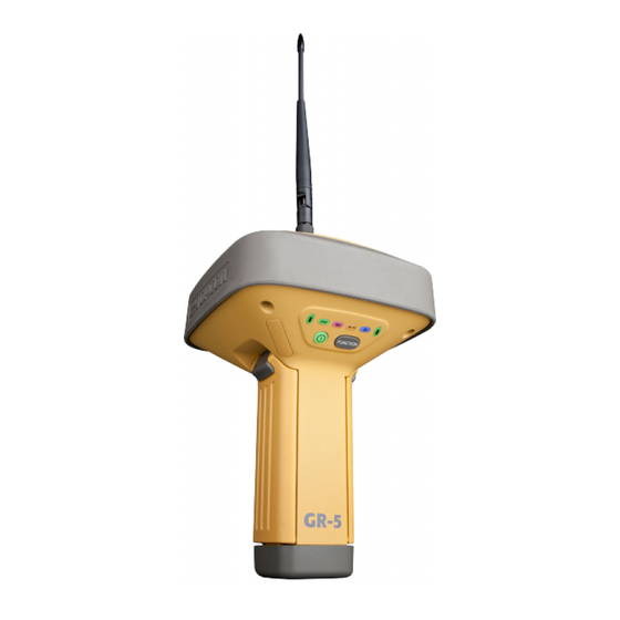
Page 22: Receiver Overview
Getting Acquainted • • • • • • The GR 5 receiver enclosure is fully sealed and incorporates the GNSS receiver board, antenna, batteries, memory storage, and wireless communication device. Receiver Overview The upper portion of the receiver contains the GNSS antenna, which is enclosed by the radome and securely surrounded by a shock absorbing rubber bumper. -
Page 23: Cables
Cables The GR 5 package includes a power supply cable, a USB cable, and a power adapter. Table 1 describes the cables included with your receiver. Align the keyways when connecting the power/serial cable to the receiver port. Turn the cable lock clockwise until it clicks to secure the cable in place. - Page 24 Table 1. Receiver Cables Cable Description Cable Illustration USB Cable Connects the receiver to an external device (controller or computer) for data transfer and receiver configuration. p/n 14 008070 01 Receiver Power/Charging Cable Connects the receiver and the power supply unit via SAE connectors for battery charging.
-
Page 25: Accessories
Accessories Topcon offers a wide variety of accessories specially designed to improve system flexibility and job site efficiency. For more details about the available accessories, contact your Topcon dealer. • Power Supply Unit (p/n 22 034101 01): charges the detachable batteries when connected to a grounded outlet. This unit converts the alternating current (AC) normally supplied from an electrical outlet to a direct current (DC) used to charge the batteries and/or power the receiver. - Page 26 A hand held controller: allows the GR 5 Base and Rover systems to be configured and monitored directly in the field. You can use the Topcon Receiver Utility (TRU) to configure the receiver and any Topcon field data collection software.
-
Page 27: Batteries
Batteries The receiver comes equipped with two detachable, rechargeable batteries for powering the receiver. For more information about using the batteries, see “Managing Power” on page 30. Detachable Battery Detachable Battery Figure 4: GR 5 Detachable Batteries P/N: 7010 1004 Batteries... -
Page 28: Data And Power Ports
Data and Power Ports The GR 5 has the following three ports: • USB – rimmed in yellow; used for high speed data transfer and communication between the receiver and an external device. The body of the connector Serial Power on the corresponding cable is yellow. -
Page 29: External Radio Antenna Connector
External Radio Antenna Connector The radio antenna connects to the external antenna connector on the GR 5 radome (Figure 5). The radio antenna uses a reverse polarity TNC connection or BNC connection depending on the installed radio modem. External Antenna Connector Figure 5: GR 5 Radome and External Antenna Connector P/N: 7010 1004... -
Page 30: Bottom Connector
Bottom Connector The bottom connector (Figure 6) connects the receiver to either a standard 5/8'' thread pole/adapter or the quick disconnect. The quick disconnect adapter (p/n: 02-850905-01??) connects to the range pole for the receiver to slip into the top. Using the side clips, the receiver can be quickly connected to/disconnected from the range pole. -
Page 31: Sd/Sdhc And Sim Card Slots
SD/SDHC and SIM Card Slots The SD/SDHC and SIM card slots are located under the battery compartments near the base of the dome. For more information about the SD/SDHC card, see “Memory” on page 61. For more information about SIM cards, see “SIM Card Slot”... -
Page 32: Sim Card Slot
SIM Card Slot The SIM card slot is located to the right of the LED Display Panel inside the battery compartment. It enables you to install a standard SIM card into the receiver. Once installed, the SIM card provides a unique identification for the receiver’s GSM/CDMA module and enables the receiver’s GSM/CDMA... - Page 33 Display Panel Operations • • • • • • The LED display panel (Figure 8) enables you to control receiver power and data recording. The LEDs display the status of the satellite tracking, recording/memory capacity, Bluetooth connections, and batteries. This chapter describes the different LED blink patterns and what they mean.
-
Page 34: Power Button
Power Button The power button turns the receiver on and off. When turning the receiver on, press the Power button until the LEDs briefly flash. When turning off the receiver, press the Power button until the LEDs go out. Press the power button for about 1 second to turn the receiver on/off. -
Page 35: Function Button/Logging Data
FUNCTION Button/Logging Data This button switches the receiver between information modes and post processing modes, starts/stops data recording, and changes the baud rate of the serial port to 9600. The FUNCTION button enables you to turn data recording on or off. See Table 2 to learn how to use the FUNCTION button. - Page 36 Table 2. FUNCTION Button Operations and REC LED Status FUNCTION Key REC LED Status When data recording is off, and the FUNCTION key is... No light No data recording. Orange blink Internal file system test in progress. Not pressed No free memory; hardware problem with data recording. No SDHC card.
- Page 37 Table 2. FUNCTION Button Operations and REC LED Status (Continued) FUNCTION Key REC LED Status Pressed for 5–8 Release to turn serial port A baud rate to 9600 bps. seconds Pressed for > 8 No light No function. seconds When data recording is on, and the FUNCTION key is... No free memory;...
- Page 38 Table 2. FUNCTION Button Operations and REC LED Status (Continued) FUNCTION Key REC LED Status If FUNCTION key mode is “LED blink mode switch” Orange Release to change information mode. Pressed for < 1 second If FUNCTION key mode is “Occupation mode switch” Orange Release to toggle between Static and Kinematic post processing modes.
-
Page 39: Battery Led
Battery LED The Battery LED indicates the remaining charge of each detachable battery. When an external power source is utilized, the LED turns green and begins to blink if the batteries begin to charge. See Table 3 for more information. Table 3. -
Page 40: Receiver Status Leds
Receiver Status LEDs There are four status LEDs to provide you information about the battery life, tracked satellites, memory capacity, and Bluetooth wireless connectivity. This section describes the color and behavior of each LED. RX TX LED This LED displays the status of the modem. Table 4 describes the LED colors and patterns for the different modems available for the GR 5 receiver. - Page 41 Table 4. RX TX LEDs Satel Transceiver Green Flashes (green LED, off, green LED) Modem is ready to receive data (FCS OFF or RX Slave) Green with Yellow (green LED, green LED + red LED) Modem is receiving data (Yellow during actual reception) Solid red Tx Master Green with Red (green LED, red LED)
-
Page 42: Stat Led
STAT LED The tracking status LED displays how many satellites the receiver is tracking. Table 3. Status LED Patterns LED Color Description One blink per tracked GPS satellite. One blink per tracked GLONASS satellite. One blink when there are no tracked satellites or solutions. -
Page 43: Bluetooth Led
Table 4. Recording LED Patterns Display Description Green Blink: File logging is in progress. Each blink indicates data is being written to the SDHC card. Solid Orange: The receiver is changing modes. Orange Blink: The file system is not accessible. Solid Red: A fault condition with the receiver (no more memory, no SDHC card inserted, a hardware problem, or an improper OAF. -
Page 44: Turning On/Off The Receiver
Managing Power • • • • • • This chapter describes how to power the receiver, charge the detachable batteries, and use an external power source. Turning On/Off the Receiver To turn on the receiver, press and hold the power button until the LEDs briefly flash. When the receiver is turned on, the receiver’s channels initialize and begin tracking all visible satellites at any time and location. -
Page 45: Detachable External Batteries
5 and 10 hours of operation, depending on the receiver mode. For more information, see Table 6. To check the status of the detachable batteries, view the BATT LED or check the status using available Topcon software. Check the BATT LEDs for battery status: •... -
Page 46: Charging The Batteries
Table 6. Estimated Operating Times Using Two Fully charged Batteries For the GR-5 with Satel Modem Receive only mode 14 hours 0.5W transmission mode 12 hours 1W transmission mode 11 hours GSM/HSPA in urban areas 12 hours Common Conditions: 10–12 SV tracked; using the detachable batteries; room temperature... - Page 47 Power Supply Unit The power supply unit (p/n 22 034101 01) charges the external batteries when connected to a grounded outlet. This unit converts the alternating current (AC) normally supplied from an electrical outlet to a direct current (DC) used to charge the batteries and/or power the receiver.
- Page 48 To grounded outlet To Grounded Outlet To Receiver Figure 11: Power Supply Unit Battery Charging Cradle The battery charging cradle (Figure 12) connects to a standard power outlet using the power adapter cable and power cable/power supply unit. The charger has two ports, one button, and three LEDs. •...
- Page 49 • The STATUS button activates the battery LEDs. Press STATUS to display the amount of charge for the corresponding battery. • The two battery LEDs display the percentage of charge in the attached battery: – A green light indicates a charge greater than 85%. –...
-
Page 50: Charging Temperatures
You can also attach the battery charger to a tripod, a belt, or an RTK pole to provide external power to the base station or rover. Before using the GR 5, fully charge the batteries for maximum operating time. Charging Temperatures Charge the batteries only in temperatures between 32 F (0 C) and 113... -
Page 51: Leaving The Batteries On Charge
1. Plug the receiver to SAE power cable into the receiver’s power input port. 2. Connect the receiver to SAE power cable and the power supply to outlet cable to the AC adapter. 3. Plug the power supply to outlet cable into an available outlet. -
Page 52: Attaching The Batteries
The batteries can also be attached/detached to/from the receiver or charging cradle at any time without harming the batteries, the receiver, or the cradle. When returning the batteries to the receiver or cradle, charging is automatically resumed. Attaching the Batteries To attach the batteries to the GR 5 (Figure 13): 1. -
Page 53: Detaching The Batteries
Detaching the Batteries To detach the batteries from the GR 5, so that they can be charged or replaced: Using the clip at the top of the battery, gently pull down and out to detach the battery from the receiver (Figure 14). Figure 14: Detach the GR 5 Batteries Assembling the AA Battery Shell To assemble the AA battery shell to the GR 5 (Figure 15):... -
Page 54: Surveying While Charging
2. Insert four AA batteries as shown on the inside of the shell (and in Figure 15 below). • The batteries on the left lay with the positive end towards the bottom of the shell. • The batteries on the right lay with the positive end towards the top of the shell. 3. -
Page 55: Changing The Batteries While Surveying
Changing the Batteries while Surveying It is safe to change a depleted battery with a fully charged one while surveying (i.e., on the fly) without turning off the receiver. Before doing this, make sure the other battery has enough charge to power the receiver while changing the depleted battery. - Page 56 3. Turn on the receiver. From receiver to auxiliary battery using ODU-to- alligator clips cable. Figure 16: Connect an Auxiliary Battery and the Receiver A single external 12 V, 2.3 A*h battery should run the receiver and modem for about 9 hours and the receiver for 13 hours. P/N: 7010 1004 Powering the Receiver...
- Page 57 To connect the receiver to the charging cradle (Figure 17): The charging cradle with extra batteries hooks onto a tripod or belt for a convenient power supply for the receiver. The part number for the receiver to charger cradle cable is 14 008072 01 or 14 008072 02. 1.
-
Page 58: Insufficient Power
• Connect the receiver to a different power source. Power supplied to the receiver should match the specifications provided by Topcon on the product. Failure to comply with these specifications may damage the receiver. See “Specifications” on page 78. P/N: 7010 1004... -
Page 59: Viewing Receiver Information
The sections in this chapter describe receiver options, and how to load a new Option Authorization File (OAF), update firmware, and perform a factory reset. To do this, you will need to use the Topcon Receiver Utility (TRU) software that was supplied on the GR 5 CD. - Page 60 Figure 6: TRU – Receiver Info P/N: 7010 1004 Viewing Receiver Information...
-
Page 61: Loading New Firmware
Loading New Firmware Receiver board firmware is released as a compressed file that you download and decompress. This file contains the following two files: • ramimage.ldr – the Receiver board RAM file • main.ldp – the Receiver board Flash file To upload firmware files to the receiver: 1. - Page 62 Select USB Port Figure 7: Connection Parameters Window 3. Click the Firmware icon in the TRU main window. The Upload Firmware window (Figure 8) displays. This window enables you to upload firmware files to the connected receiver. 4. Make sure Receiver is selected in the Device field. 5.
- Page 63 Figure 8: Upload Firmware Window 7. Click Start to upload the selected files. 8. Click OK to continue uploading new firmware to the receiver (see Figure 9). P/N: 7010 1004 Loading New Firmware...
-
Page 64: About The Oaf
About the OAF Topcon issues an Option Authorization File (OAF) to enable the specific options that you purchased. Topcon’s OAF system allows you to customize and configure the receiver according to your particular needs, therefore purchasing only the options you require. -
Page 65: Checking The Receiver's Oaf
Checking the Receiver’s OAF To use TRU to view the status of the receiver’s options: 1. Connect the receiver to a computer and open TRU. See the Topcon Receiver Utility (TRU) Reference Manual for more information about connecting the receiver to a computer. -
Page 66: Loading An Oaf
Figure 10: Receiver Options Loading an OAF Topcon dealers provide customers with OAF files. For any OAF related questions, e mail Topcon at options@topcon.com and include the receiver’s ID and serial number. To obtain these numbers, see “Viewing Receiver Information” on page 45. - Page 67 4. Select the appropriate file, and click Open (Figure 11). Topcon’s TRU initially checks to see if the selected file is compatible with the currently connected receiver. If you chose a file not intended for this receiver, the Upload OAF window displays an error icon next to the Receiver ID and disables the Upload the File to the Receiver button.
- Page 68 Figure 12: OAF Compatibility Check 5. Press Upload the File to the Receiver (Figure 12) to start loading the file. If an OAF file is uploaded to the receiver, TRU will offer to reset the receiver to put new authorization options into operation (Figure 13).
-
Page 69: Clearing The Nvram
You can also use TRU to clear the NVRAM: 1. Connect the receiver to a computer, and open TRU. See the Topcon Receiver Utility (TRU) Reference Manual for more information about connecting the receiver to a computer. - Page 70 3. Click the Tools icon in the main window. The Tools window appears, enabling you to reset the receiver and clear the NVRAM. Figure 14: Tools Dialog Box 4. Click Factory Reset, and click Yes to continue. P/N: 7010 1004 Clearing the NVRAM...
-
Page 71: Setting Up The Base Receiver
Setting Up the Base Receiver 1. Install a heavy duty tripod (p/n: 22 050501 01) over a known point. You do not need a universal GR-5 Receiver tribrach and tribrach adapter when working with this tripod. 2. Attach the antenna to the modem antenna connector. -
Page 72: Setting Up The Rover Receiver
Setting Up the Rover Receiver 1. If needed, attach the quick disconnect to the bipod/range pole. GR-5 Recevier Use a bipod during post process Quick Disconnect (Optional) surveys to ensure the antenna/receiver does not 5/8 inch Screw move during data logging. -
Page 73: Measuring Antenna Height
Measuring Antenna Height The receiver calculates the coordinates of the antenna’s phase center. To determine the coordinates of the station marker, specify the following: • Measured height of the antenna above the station marker • Method of measuring the antenna height •... - Page 74 SHMM 168mm A = ARP to edge = 79.0 B = ARP to corner = 97.5 LV LS LV = Vertical Length LS = Slant Length Figure 18: Antenna Height Measurement Points P/N: 7010 1004 Measuring Antenna Height...
-
Page 75: Memory
Collecting Data • • • • • • This chapter provides general information about memory, recording data, downloading data, and removing files to free up memory space. Memory The GR 5 is equipped with an external SD/SDHC memory card slot. Although you may install an SD/SDHC card of any memory size into the slot, the receiver recognizes only up to 2 GB of memory. -
Page 76: Sd/Sdhc Card
Transcend® Ultra Industrial 2 GB • APRO® Industrial 4GB • SanDisk® Ultra II • Swissbit® Industrial 2GB Use only industrial grade SD/SDHC cards. Before using any other SD/SDHC cards, consult with Topcon Customer Support about compatibility. P/N: 7010 1004 Memory... -
Page 77: Installing The Sd/Sdhc Card
Installing the SD/SDHC Card 1. Make sure the receiver is turned off. 2. Remove the detachable battery to the left of the LED Display panel. 3. Carefully insert the SD/SDHC card, label side down, into the card slot located at the top of the battery compartment. -
Page 78: Initializing The File System Using Tru
Setting Recording Parameters The Topcon Receiver Utility (TRU) software enables you to set logging parameters, such as logging rate and types of messages, in which to record data. This software and the TRU Reference Manual is supplied on the GR 5 CD. See the TRU Reference Manual for more information. -
Page 79: Recording Data
Recording Data You can log raw GNSS data to the receiver’s SD/SDHC card and use the Topcon Receiver Utility (TRU) or MAGNET Office™ software to download the files to a computer. To start or stop recording data, use the LED display panel or TRU: 1. -
Page 80: Managing Files
*.tps file extension. You can then transfer a file of collected data can to a computer with file managing software, such as the Topcon Receiver Utility (TRU), which is supplied on the GPS+ CD. These programs allow you to use an automatic naming feature, enter file names, and delete files as necessary. - Page 81 Once a connection is established, you can download all or some files to a computer or controller and then use the File Explorer feature in Topcon Receiver Utility (TRU) to manage the raw data files. For more information about using TRU to download or delete files, see the Topcon Receiver Utility (TRU) Reference Manual included on the GR 5 CD.
-
Page 82: Check This First
• Check the software. Make sure the most current software version is downloaded onto the computer and the most current firmware is loaded into the receiver. Check the Topcon website for the latest updates. • Check Topcon Technical Support (www.topconsupport.com) or Topcon Total Care (www.topcontotalcare.com) for the latest updates. -
Page 83: Powering Problems
The receiver may have a defective charger or defective battery. – If, after changing the battery or connecting an external power source, the receiver still does not power up, contact your local dealer or Topcon Technical Support for advice. P/N: 7010 1004... -
Page 84: Receiver Problems
Generic problems: • The receiver port used for connection is not in Command mode. Connect the receiver to a computer and open TRU (see “Connection” in the Topcon Receiver Utility (TRU) Reference Manual). b. Click Receiver Settings Ports. Change the Input Mode for the port used for connection to cmd. - Page 85 – Order a new OAF with the desired options activated to enable or extend validity of the corresponding receiver options. Contact a dealer or visit the Topcon website for details. – Refer to the “Receiver Managing” chapter of the Topcon Receiver Utility (TRU) Reference Manual for a detailed description of options.
- Page 86 A discrepancy exists between the differential standards used at the Base and Rover receivers. – Ensure the Base and Rover receivers use the same corrections input/output format: Connect the receiver to a computer and open TRU (see “Connection” in the Topcon Receiver Utility (TRU) Reference Manual).
- Page 87 The SD/SDHC card is not properly inserted. • The receiver’s memory is disabled or expired. – Make sure the memory option is enabled. For details, see the Topcon Receiver Utility (TRU) Reference Manual. • The memory card does not have free space.
-
Page 88: Bluetooth Problems
– Disconnect the receiver from the other controller or computer. • The receiver port used for connection is not in Command mode. Connect the receiver to a computer and open TRU (see “Connection” in the Topcon Receiver Utility (TRU) Reference Manual). b. Click Configuration Receiver Ports. - Page 89 Change the Input Mode for the Bluetooth serial port used for connection to cmd. This is the most common cause for this error message. Use TRU to double check the settings for the connection port. TRU error message: Open COM# port failed: Access is denied •...
-
Page 90: Tru Problems
If the settings are changed for the Bluetooth module, remove it from the list of discovered Bluetooth devices using the Bluetooth manager program (supplied with the device used to manage the receiver). b. Repeat the search. TRU Problems The following is the most commonly encountered TRU problem. TRU cannot connect to the receiver •... -
Page 91: Cleaning And Storing The Receiver
Always make sure the receiver is completely dry before storing it. Dry any moisture with a soft, clean cloth. Getting Customer Support If the troubleshooting hints and tips in this operator’s manual fail to remedy the problem, contact Topcon Customer Support. For contact information, see “Getting Technical Support” on page 6. -
Page 92: General Details
Table 7 lists the receiver’s general specifications. Table 7. General Receiver Specifications Physical Enclosure Magnesium, IPX 6 extrusion, rainproof Color Topcon Yellow and Gray (bumper) Dimensions (mm) 158.1 (w) x 253 (h) x 158.1 (d) Weight 1.88 kg with batteries, 1.44 kg without batteries Antenna... - Page 93 Table 7. General Receiver Specifications Mounting 5/8 11, quick disconnect Seals Silicon (molding in color) Keys Two keys: • Power – On/Off • Function – start/stop data logging; switch information mode LEDs Six LEDs: • STAT – satellite and receiver status •...
- Page 94 Table 7. General Receiver Specifications Waterproof rating IPX7 (1 meter submersion) Dust rating IP6X (Fully dust proof) Random vibration MIL STD 202G, Method 214A, Test Curve A, 5.35g RMS Sinusoidal vibration SAE J1211:1978 Section 4.7, 4g Peak Shock IEC 60068 2 27 edition 4, Table A.2 25g, 6ms Topple 2.0m pole drop...
- Page 95 Table 7. General Receiver Specifications Operating time • Modem = off – approx. 20 hours • AA sized battery shells attached to both battery slots and modem Average with modem “on” is off – approx. 2.5 hours and 12 SVs tracked. FH915 •...
- Page 96 Table 7. General Receiver Specifications Consumption • Modem = off – approx. 2.5 W • Urban areas with short distance to cell sites and GSM/GPRS is on Average with modem “on” – approx. 4.2 W and 12 SVs tracked. FH915 •...
- Page 97 Table 7. General Receiver Specifications On board Backup battery for timekeeping and almanac data storage; 10 years minimum operation Communication Ports A high speed RS232 serial port (rimmed in black), a USB port (rimmed in yellow), and an internal Bluetooth communication port (port D).
- Page 98 Technology • Topcon Vanguard™ ASIC technology • Fence Antenna™ Technology • Topcon Advanced Multipath Rejection (AMR) • Integrity Monitoring (RAIM) • Topcon Automatic File Rotation Mode (AFRM) • Universal Tracking Channels NMEA Ver. 2.1, 2.2, 2.3, 3.0 output NMEA version...
- Page 99 Table 7. General Receiver Specifications GGA, GLL, GNS, GRS, GSA, GST, GSV, HDT, RMC, VTG, ZDA, ROT, Messages GMP, UID, P_ATT 1Hz standard; 5, 10, 20, 50, 100 Hz optional Output internal DGPS Correction format RTCM SC104 Ver 2.1, 2.2, 2.3, and 3.0 RTCM message type 1, 3, 9, 31, 32, 34;...
- Page 100 Table 7. General Receiver Specifications Baseline Length Up to 50km in the morning and evening. Up to 32km at noon. Initialize time 5 seconds to 10 min depending on the base line length and multipath conditions Output interval for 1Hz standard; 5, 10, 20, 50, 100 Hz optional CMR/RTCM Elevation 0 to 90 degrees (independent of data logging)
- Page 101 Table 7. General Receiver Specifications Base or Rover Static Kinematic (Stop and Go) RTK (Real-time Kinematic) DGPS (Differential GPS) WASS/EGNOS DGPS Survey Accuracy Static, Fast Static For L1 – H: 3mm + 0.8ppm (x baseline length); V: 4mm + 1ppm (x baseline length) For L1+L2 –...
- Page 102 Table 7. General Receiver Specifications <= 10 sec Hot Start <= 30 sec Warm Start <= 60 sec Cold Start <= 1 sec Reacquisition Communication Serial 1 port; Hirose H205 Series (6 pin, multiplex); RS232 RX/TX 1 port; USB Mini B 2.0 (client) Bluetooth v2.1 + EDR Cellular...
- Page 103 Table 7. General Receiver Specifications DGPS H: 0.4 m V: 0.6 m SBAS H: 1.0 m V: 1.5 m a. CMR/CMR+ is a third party proprietary format. Use of this format is not recommended and performance cannot be guaranteed. Use of industry standard RTCM 3.x is always recommended for optimal performance.
-
Page 104: Gps Board Details
Receiver Type (set by activating the proper OAF) Internal board: GPS: L1/L2 C/A & P (Y) -code, L2C, L5 full wave carrier GR-5 GLONASS: L1, L2 C/A & P-code full-wave carrier GALILEO: Giove-A, Giove-B (E & E5a) SBAS (WAAS/EGNOS/MSAS) L1 code & carrier... - Page 105 Cinderella days is an option that turns a single frequency, GPS receiver into a dual frequency, GNSS GLONASS receiver for 24 hours every other Tuesday at GPS midnight. Refer to Topcon’s website for more information and specific Cinderella day dates.
-
Page 106: Bluetooth Module Details
Bluetooth Module Details Table 9. Bluetooth Module Specifications Range up to 10 m (indoor); up to 20 m (outdoor) Type Class 2 Service classes Miscellaneous Supported profiles LM, L2CAP, SDP, SPPP Frequency Country Code North America and Europe Range up to 10 m (indoor); up to 20 m (outdoor) Type Class 2 Service classes... -
Page 107: Connector Specifications
Table 9. Bluetooth Module Specifications Frequency Country Code North America and Europe Range up to 10 m (indoor); up to 20 m (outdoor) [[Do you want to list all of the modem specifications?? We can if you want??]] Connector Specifications The GR 5 has one antenna connector for radio transmission/reception and three port connectors for power and data upload/download. -
Page 108: Power Connector
Table 9-1. Modem Connector Specifications Modem Type Signal Type Details Digital/Satel Modem I/O RF/GSM input/output to/from modem antenna Power Connector Rimmed in red, the power connector (Figure 9 1) is a sealed receptacle, 5 pin, ODU part number G80F1C T05QF00 0000. Figure 9-1. - Page 109 Table 9 2 describes power connector specifications. Table 9-2. Power Connector Specifications Number Signal Name Details Power_INP 9 to 21 volts DC input Power_INP 9 to 21 volts DC input Power_GND Ground, power return Power_GND Ground, power return Aux_Power 9 to 21 volts DC input P/N: 7010 1004 Connector Specifications...
-
Page 110: Serial C Rs232 Connector
Serial C-RS232 Connector Rimmed in black, the serial RS232 connector (Figure 9 2) is a sealed receptacle, 7 pin, ODU part number G80F1C T07QC00 0000. Figure 9-2. Serial RS232 Connector Table 9 3 gives the RS232 cable connector specifications. Table 9-3. RS232 Connector Specifications Number Signal Name Details... -
Page 111: Usb Connector
Table 9-3. RS232 Connector Specifications (Continued) Number Signal Name Details Receive data Transmit data Not used USB Connector Rimmed in yellow, the USB connector is a sealed receptacle, 4 pin TPS cable connector (Figure 9 3). Figure 9-3. USB Connector for GGD Options P/N: 7010 1004 Connector Specifications... - Page 112 Table 9 4 gives the USB connector specifications. Table 9-4. USB Specifications Number Signal Name Details USB_PWR Bus power input USB D Data minus USB D+ Data plus Ground P/N: 7010 1004 Connector Specifications...
-
Page 113: General Warnings
Safety Warnings • • • • • • General Warnings To comply with RF exposure requirements, maintain at least 25cm between the user and the receiver when operating LongLINK technology. TPS receivers are designed for survey and survey related uses (that is, surveying coordinates, distances, angles and depths, and recording such measurements). -
Page 114: Battery Warnings
Battery Warnings Never attempt to open the casing of the detachable batteries! Lithium Ion batteries can be dangerous if mishandled! Do not incinerate or heat the battery above 212 degrees fahrenheit (100 degrees celsius). Excessive heat can cause serious damage and possible explosion. Tampering with the batteries by end users or non factory authorized technicians will void the battery’s warranty. -
Page 115: Receiver Warnings
The owner should periodically test this product to ensure it provides accurate measurements. Inform TPS immediately if this product does not function properly. Only allow authorized Topcon warranty service centers to service or repair this product. P/N: 7010 1004 Receiver Warnings... -
Page 116: Fcc Compliance
Regulatory • • • • • • The following sections provide information on this product’s compliance with government regulations for use. FCC Compliance This equipment complies with FCC radiation exposure limits set forth for uncontrolled equipment and meets the FCC radio frequency (RF) Exposure Guidelines in Supplement C to OET65. -
Page 117: Industry Canada Compliance
• Consult the dealer or an experienced radio/television technician for additional suggestions. Any changes or modifications to the equipment not expressly approved by the party responsible for compliance could void your authority to operate such equipment. Industry Canada Compliance This equipment complies with IC radiation exposure limits set forth for uncontrolled equipment and meets RSS 102 of the IC radio frequency (RF) exposure rules. -
Page 118: Ic Rf Radiation Exposure Statement
IC RF Radiation Exposure Statement When installing, locate or point this device away from the installer, so it does not emit RF field in excess of Health Canada’s limits for the general population. Consult Safety Code 6 from Health Canada’s website at www.hc sc.gc.ca/rpb. IC Additional Statement with Detachable Antennas This device 9with UHF II modem) has been designated to operate with the antennas listed below and have a maximum gain of 2.4dBi. -
Page 119: Community Of Europe Compliance
Community of Europe Compliance The product described in this manual is in compliance with the R&TTE and EMC directives from the European Community. European Community Declaration of Conformity with R&TTE Directive 1999/5/EC The following standards were applied: (R&TTE Directive 1999/5/EEC) •... -
Page 120: Declaration Of Conformity (R&Tte Directive 1999/5/Ec)
Hereby, (Topcon) declares that this (GR-5) is in compliance with the essential requirements and other relevant provisions of Directive 1999/5/EC. Español Por medio de la presente (Topcon) declara que el (GR-5) cumple [Spanish] con los requisitos esenciales y cualesquiera otras disposiciones aplicables o exigibles de la Directiva 1999/5/CE. - Page 121 Par la présente (Topcon) déclare que l'appareil (GR-5) est [French] conforme aux exigences essentielles et aux autres dispositions pertinentes de la directive 1999/5/CE. Italiano Con la presente (Topcon) dichiara che questo (GR-5) è conforme ai [Italian] requisiti essenziali ed alle altre disposizioni pertinenti stabilite dalla direttiva 1999/5/CE. Latviski Ar šo (Topcon) deklar, ka (GR-5) atbilst Direktvas 1999/5/EK...
- Page 122 (Topcon) declara que este (GR-5) está conforme com os requisitos [Portugues] essenciais e outras disposições da Directiva 1999/5/CE. Slovensko (Topcon) izjavlja, da je ta (GR-5) v skladu z bistvenimi zahtevami [Slovenian] in ostalimi relevantnimi doloili direktive 1999/5/ES. Slovensy (Topcon) týmto vyhlasuje, že (GR-5) spa základné požiadavky a [Slovak] všetky príslušné...
- Page 123 P/N: 7010 1004 Declaration of Conformity (R&TTE Directive 1999/5/EC)
-
Page 124: Weee Directive
WEEE Directive Following information is for EU member states only: The use of the symbol below indicates that this product may not be treated as household waste. By ensuring this product is disposed of correctly, to help prevent potential negative consequences for the environment and human health, which could otherwise be caused by inappropriate waste handling of this product. - Page 125 Korean KC-RF Compliance KCC-CRM-T8S-1000036-01 Korean KC-EMC Class A Statement P/N: 7010 1004 Korean KC RF Compliance...
- Page 126 The purchaser’s sole remedy shall be replacement as provided above. In no event shall Topcon be liable for any damages or other claim including any claim for lost profits, lost savings or other incidental or consequential damages arising out of the use of, or inability to use, the product.
- Page 127 Glossary • • • • • • Base Station – A GNSS receiver set up over a known point, which is used to derive correction information for nearby Rover (mobile) GNSS receivers. Bluetooth® – Often used in place of cables, Bluetooth is open wireless technology for exchanging data over short distances from fixed and mobile devices.
- Page 128 L1 – The primary L band carrier used by GPS and GLONASS satellites to transmit satellite data. L2 – The secondary L band carrier used by GPS and GLONASS satellites to transmit satellite data. Light Emitting Diode (LED) – Used as indicator lights on the receiver to display the status of the receiver’s components and control receiver operations.
- Page 129 Static Survey – Typically uses a network or multiple baseline approach for positioning. This method provides the highest accuracy and requires the longest observation times. Topcon Receiver Utility (TRU) – Hardware configuration software for receivers and peripheral devices. TRU is included on the GPS+ Software CD that accompanied your receiver.
- Page 130 Universal Serial Bus (USB) – A connection standard used by devices, such as a receiver, controller, computer, etc. P/N: 7010 1004...
Need help?
Do you have a question about the GR-5 and is the answer not in the manual?
Questions and answers