MSSC Smart-Jet BLUE User Manual
Thermal inkjet coder
Hide thumbs
Also See for Smart-Jet BLUE:
- Manual (97 pages) ,
- User manual (67 pages) ,
- User manual (35 pages)

Subscribe to Our Youtube Channel
Related Manuals for MSSC Smart-Jet BLUE


Summary of Contents for MSSC Smart-Jet BLUE
- Page 1 T H E R M A L I N K J E T C O D E R USER’S MANUAL Pro Pack Solutions, Inc. 770-554-1187...
-
Page 2: Table Of Contents
SAFETY INFORMATION ..............................4 PRODUCT WARRANTY ..............................4 ABOUT MACHINE ................................ 4 TECHNICAL SPECIFICATIONS ............................5 Machine details ................................5 Keyboard ..................................5 Android devices ................................5 MACHINE OVERVIEW ..............................6 Indicator LED ................................6 Connecting Port ................................7 Keyboard ..................................7 Operation menu with keyboard .......................... - Page 3 Printer Controller Interface ............................67 Create new message ..............................67 APPENDIX.................................. 78 INK CARTRIDGES MAINTENANCE ..........................78 Print head cleaning ..............................78 Wiping ..................................78 Important notes ................................ 79 Purging ..................................79 INK CARTRIDGE STORAGE PROCEDURE ........................80 Important handling cautions ............................ 80 UPDATE FIRMWARE INSTRUCTIONS ..........................
-
Page 4: Safety Information
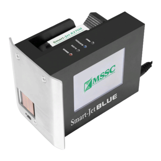
Unapproved, wrong or unstable power supply is used. ABOUT MACHINE Thank you for purchasing the Smart-Jet BLUE Thermal Inkjet Coder, a product of MSSC LLC, US. This printer is designed for packaging printing applications powered by HP Thermal Inkjet Technology. -
Page 5: Technical Specifications
TECHNICAL SPECIFICATIONS Machine details Description Specifications Model Smart-Jet BLUE LCD 2.8” automatic rotation Display Dimensions (Lx W x H) 107.5 x 74.5 x 83 mm / 4.23 x 2.93 x 3.27 in Weight 450g AC 100V – 240V, 50/60Hz, 1.4A... -
Page 6: Machine Overview
MACHINE OVERVIEW Indicator LED Items Detail Default setting is don’t recognize black conveyor [1] Sensors Internal sensor: Red light. External sensor: Green light. Sensor is activated when receives signals [2] Error Reports errors during operation. [3] Bluetooth/PC Remains ON when being connected Remains ON when it’s on printing mode. -
Page 7: Connecting Port
Connecting Port Items Detail [1] USB FLASH USB 2.0 flash for updating firmware, fonts and logo [2] USB KEYBOARD For USB 2.0 wireless keyboard receiver [3] USB PC PORT For PC connection with USB 2.0 cable A-B Extend port for external sensor, encoder, alarm, etc… [4] DB15 EXTENDED PORT [5] 12VDC PORT Power supply... -
Page 8: Operation Menu With Keyboard
Operation menu with keyboard Main Menu Message Operation Setting Open Create new Information Purge Start/Stop Connect PC Speed Resolution Density Select font Select size Delay Cartridge Update logo Insert Menu Edit String Random Jet Print Side (Popup menu when press Inset) Delete Symbol Logo... - Page 9 Operation Menu Description Start / Stop Start or Stop printing job. Combine and press CTRL + SHIFT + ENTER on keyboard to fast Start / Stop print. Purge All of nozzle on cartridge will push out ink. After purged you will see 2 lines of ink on substrate.
- Page 10 Default Reset machine to factory default. Language Select your interface language. Or add more interface language from USB flash. IO signals The extend button to re-start machine. This will help in some special case. Custom string Update the custom strings via USB flash that are created from application on PC.
-
Page 11: Operation Menu With Pc Software
Operation menu with PC software PC Application Menu Printer Control Screen Designing Screen Tools About Edit Open Print Head Printer Printing Purge Ink Cost Setup Setup Status Template Template Template Export Save Switch Connection Convert Template Delete Unit Event Log nozzle Status Logo... - Page 12 Turn ON Status and set the time for purging in the Time by click up or down at or input the desired value. This value is adjustable from 5s to 1,000s. Encoder Encoder is recommended to optimize maximum print quality. Turn ON Encoder to operate Machine with encoder.
- Page 13 Input distance from external sensor to the print head, set Delay before and Delay after print to have your message printed at the desired position. Continuous Mode Machine will print continuously when a sensor is triggered for the first time. When Continue mode is applied, distance between the messages on the same object should to be set.
- Page 14 Displays the number of pages printed (left) per the total pages to print (right). Select page to start / end printing, apply for counter, barcode. The data will continue to be printed from the start page. Printer Controller Print: Select to print Pause: Select to temporary stop printing Stop: stop printing.
- Page 15 New template: Create new message with free template design. Open: Open message from PC. Save template: Save message to PC. Export to .tiff files: Export message in Tiff format. Delete: Delete object. Cut: Cut object. Copy: Copy object. Paste: Paste object. Select Tool: Select to function and edit each object on the message.
- Page 16 Purge: all of nozzle on cartridge will push out some ink. This will help clean all cartridge. Ink Cost: calculate number of printing job, ink price, price for each print. Event Log: view all of action that user did on application. Convert logo: use to convert photo / image / logo / text to HEX file and update to the printers.
-
Page 17: Getting Started
GETTING STARTED Install the machine on your conveyor according to the installation instructions. See the Quick Installation Guide (included inside package) for more information. Set print direction and appropriate throw distance to obtain best print quality (1-3 mm). Insert ink cartridge. -
Page 18: Installation Procedures
INSTALLATION PROCEDURES MOUNTING BRACKETS Step 1 Skid plate adjust depending on direction of your production line. Select direction to mount machine on the conveyor. Skid plate can be assembled as A or B position depending on the direction of the products on the conveyor. Default machine will be set at B position. - Page 19 Step 1: Installing the clamps to the side of the conveyor USER MANUAL V02 | Updated 18-Jan-2016...
- Page 20 Step 2: Installing the clamps to the round bar MOUNTING OPTIONS Select the suitable bar length Horizontal setup USER MANUAL V02 | Updated 18-Jan-2016...
- Page 21 Vertical setup Step 1: Step 2: NOTES: Make sure the brackets are mounted firmly to avoid vibration and sway of the print head. This will affect the print quality. USER MANUAL V02 | Updated 18-Jan-2016...
-
Page 22: External Devices Connections
EXTERNAL DEVICES CONNECTIONS NOTES: Machine is able to operate with External Sensor, Encoder, Alarm at a time. Consult your supplier for further supports on the settings and connections. To connect machine with External Sensor, Encoder, Alarm, etc…, additional connector DB15 (male) will be required. -
Page 23: Encoder
ENCODER An encoder is recommended to ensure the best print quality regardless the inconsistent speed of conveyor. To calculate wheel diameter (D) depend on resolution (R) is: D = R/( x 600) (inches). Example: Encoder has R = 3600 (PPR), ... -
Page 24: Combine External Sensor And Encoder
COMBINE EXTERNAL SENSOR AND ENCODER In some case you need to use external sensor and encoder to get perfect printing quality. But the machine have one extended port only. Please do as following instruction to take external sensor and encoder work together with machine. See picture for this situation. -
Page 25: Alarm
ALARM Allow users to monitor operation of Machine from distance via the light signals from the Alarm. INPUT AND OUTPUT Input: To trigger some functions (reset counter …). Accept NPN or dry contact. Output: NPN signal. Active when some even occur (each print …). RS485 PROTOCOL Allow control machine via RS485 network from other devices like: PLC, PC…... - Page 26 Diagram connect some machines to RS485 network with PCL and PC use to control. The PC need to use some converters to support RS485 protocol. CASE A: use the PC as MASTER with USB to RS485 converter. CASE B: use the PLC as MASTER. Then connect PLC to a PC. Step 2 On machine, go to Setting ...
-
Page 27: Quick Startup
QUICK STARTUP REQUIRED COMPONENTS Basic Components With keyboard With smartphone With PC Optional Machine Wireless keyboard Power supply Mounting brackets USB flash Ink cartridge ... -
Page 28: Keyboard Setup
Keyboard setup Insert the receiver of wireless keyboard to USB port (port 2) on machine, remove the protected stamp in the battery slot and turn on the button at the back of the keyboard to begin operating machine with wireless keyboard. ... - Page 29 Step 5 Return home screen of application to send command to machine. These pictures show how to search, setup PIN and connect to machine with a smartphone and an application. Tap on Searching… button to discover all of printer in Allow application access your Bluetooth connection.
- Page 30 Tap on name of printer that match with At first time setup connection, the Bluetooth connection your printer need to connect. need setup PIN code. Input the PIN code that you already setup at Step 1. Tap Ok after that. You will get a text that shows information about connection status.
-
Page 31: Pc Connection Setup
PC connection setup Be sure you have a PC plugged in connected with machine via a USB A-B cable. Install Controller Application and Driver of machine to your PC. From the main screen of machine, go to Operation and select Connect to PC to connect machine with PC. - Page 32 Press “ESC” to exit. Select Enter the name of message “Save” to save your messages Done! On smartphone (Standalone mode) Taps on “messages” Messages Designer will open. Select font type, font size if you need. Input the messages to text box (max up to 6 lines) Tap Send button after complete.
-
Page 33: Keyboard Operation
KEYBOARD OPERATION From the main screen, use and arrow keys to select the desired menu: Message, Operation, or Settings. Press Enter to select. Press ESC to go back to the main screen. Message Create new or open existing messages on the machine memory. NOTES: While doing this, please be sure you already stop printing. - Page 34 µ ¶ · ¸ ¹ º » ¼ ½ ¾ ¿ × Ø Þ In the input section on machine, press Insert and use or arrow keys to move the cursor to Symbol and press Enter. Use the arrow keys to move your cursor to the desired object and press Enter to insert the symbols into message.
- Page 35 Example To print the following counter on each object: 001, 003, 005….101, 001, 003, 005 … Start: 1 Current: 1 Reset: 101 Step: 2 Up/Down: Up Fill zero: Enable NOTES: User can insert up to 6 independent counters in one message. Box/Lot Is a dual counter.
- Page 36 Follow below steps to set counter: Step 1 Setup Counter 1 first and insert into the message Counter 1 Start: 0 Current: 0 Reset: 20 Step: 1 Up/Down: Up Fill zero: Enable Step 2 Then setup Counter 2 and insert into the same message Counter 2 ...
- Page 37 Format Select your desired format below to input into the Format section. Otherwise, date will not be displayed in the message. Day: d or dd. Month: M, MM or MMM. Year: yy or yyyy. Julian date: JJJ. Example ...
- Page 38 Hour: h, hh. AM or PM: tt. String Insert a string of data as setup in the Settings. From the input section of new message, move the cursor to the position where a string will be inserted and press Insert. Then use ...
- Page 39 NOTES: If you would like to print static 2D barcode. Please use with update logo support. Create 2D barcode as image, use smartphone or application on PC to load it to machine. Use smartphone: see Update logo. Use PC: see Use Convert Logo Create 2D static barcode with smartphone The application on smartphone will support you create new 2D barcode then you can send it directly to machine, don’t need to use USB flash or PC application.
- Page 40 Input barcode value, resize it Tap on Generate barcode to You will be transferred to Logo you need. complete your adjustment. sender screen. This will help you Select Yes to continue send to send the barcode to printer. printer. Adjust the size again with detail of size and threshold.
- Page 41 Dynamic barcode Insert dynamic barcode into your messages. Type: select your desired barcode (Code 39, Code 215, Code 128, Code 93, UPC-A, EAN, Codabar, and Code 11). Width: Input width for Barcode (value varies from 1 to 4). ...
-
Page 42: Operation
Open storage messages Open existing messages to Use / Edit / Delete. From the main screen of machine, select Message, go to Open and press Enter to go to message storage. Select your desired message and press Enter. Use or arrow keys to Use / Edit / Delete. ... -
Page 43: Settings
NOTES: Machine should be stopped before doing other settings. Shortcut key to Start / Stop: CTRL + SHIFT + ENTER. Purge Select Operation Purge to jet the ink out from all of nozzle this will help clean the print head. Connect / Disconnect PC : Select to connect or disconnect Machine with PC Settings... - Page 44 Optional resolutions with standalone mode: 300x300 dpi 300x150 dpi 300x100 dpi Optional resolutions with PC mode: 600x600 dpi 600x300 dpi 600x150 dpi 600x100 dpi 300x300 dpi 300x150 dpi 300x100 dpi Density Set the optical density of the print.
- Page 45 Delay before print varies from 5 to 500 mm. Delay after print varies from 50 to 500 mm. Cartridge Allows users to input the current amount of ink in the cartridge after inserting into the machine and display the current level of ink in the cartridge while printing. From the Settings menu, use the arrow keys to go to Cartridge and press Enter.
- Page 46 Update logo via smart phone Do as following steps to update the logo via your smartphone. Tap on logo button Tap on update logo button Tap on Choose image button Pick on photo from your library Adjust photo if you need. Tap Select the logo number memory on Use this image.
- Page 47 Waiting a moment please! Done. Logo send completed! Next to use this logo. Open Will show up Messages Designer. Tap on line of message need to insert the logo. Tap on Logo icon. Select Logo number just Keyword of Logo will appear on Tap Send to continue your sending image.
- Page 48 String Insert a string of data into messages. From the Settings menu, use the arrow keys to go to String and press Enter. Input your strings into the input section. Press ESC to apply and go back to the main menu. NOTES: ...
- Page 49 Directions Set print direction correlating the direction of the conveyor. Machine supports 4 directions: : left right, : right left, : reverse left right, : reverse right left. From the Settings menu, use the arrow keys to go to Directions and press Enter. Move to your desired direction and press Enter to confirm.
- Page 50 Update Fonts Update different fonts and character sizes for Machine. There is one font at a time on Machine. Machine supports the following fonts while working with wireless keyboard. Lines Size 12.7 mm 8.0 mm 5.93 mm 3.89 mm 2.54 mm 1.69 mm Steps to update different font/size: ...
- Page 51 Rollover Set different date depending on the shift schedules of your production. From the Settings menu, use the arrow keys to move to Rollover and press Enter. Go to Set and press Enter. Enable this function and input value at Time. Press Enter to apply (default value is 00h: 00).
- Page 52 NOTES: Language. If you don’t see your At default setting, machine just show 6 languages at Setting desired language at menu. But it inside our support languages. Please do as following. Add optional language interface For example user need change machine interface to Korean. They will need as below. Step 1 Copy all file of machine’s firmware to root folder of USB flash.
- Page 53 The machine will exit Settings menu and return Main menu with new Korean language interface. NOTES: You need do exactly 4 steps above and also press F12 with 2 times. IO signals Select start/ stop the coder from the button From the Settings menu, select IO signals and press Enter.
-
Page 54: Pc Application Introduction
PC APPLICATION INTRODUCTION Software requirement CPU: Core 2 Duo 2x2.0 GHz or higher Ram: >= 2GB Hard disk space: >= 5 GB Operating System: Window XP, Windows 7, Windows 8 (x86 / x64 bit), Window 10 (x86 / x64 bits). - Page 55 Extract setup RAR file. Right click select Install on MSI file Click Next or select other path Click Next USER MANUAL V02 | Updated 18-Jan-2016...
-
Page 56: Install Driver
Click Next Waiting for complete! Install driver When plug your machine to computer. Your Window will search the driver for machine, but it will not able to success install driver. You need install by manual. Searching driver software… USER MANUAL V02 | Updated 18-Jan-2016... - Page 57 Cannot successfully installed driver. Please do as following: Open Manage function. Extract driver. Get it from us. USER MANUAL V02 | Updated 18-Jan-2016...
- Page 58 Look at Other devices. “Thermal Inkjet Coder” is our machine. Right click. Select Update Driver Software. USER MANUAL V02 | Updated 18-Jan-2016...
- Page 59 Select Browse my computer for driver software. Select Browse to locate to driver folder. USER MANUAL V02 | Updated 18-Jan-2016...
- Page 60 Locate to folder driver. Click Next to continue. USER MANUAL V02 | Updated 18-Jan-2016...
- Page 61 Got security issue with Window. No problem, “Install this driver software anyway”! Wait a moment, and here your driver installed success. USER MANUAL V02 | Updated 18-Jan-2016...
-
Page 62: Install Driver On Window 8
Look at Device Manager, you will see Thermal InkJet Coder device appear here. NOTES: If your PC uses Window 8 64bits, please do one next step Disable signature enforcement before you install the driver. Install driver on Window 8 Press the Win + C keyboard combination to bring up the Charms Bar, and then click on the Settings Charm. - Page 63 When the Control Panel opens, switch over to the “Update & recovery” section. Then click on the Recovery option on the left hand side. Once selected, you will see an advanced startup section appear on the right hand side. You will need to click on the “Restart now”...
- Page 64 Once your Computer has rebooted you will need to choose the Troubleshoot option. Then head into Advanced options. USER MANUAL V02 | Updated 18-Jan-2016...
- Page 65 Then Startup Settings. Since we are modifying boot time configuration settings, you will need to restart your Computer one last time. USER MANUAL V02 | Updated 18-Jan-2016...
- Page 66 Finally, you will be given a list of startup settings that you can change. The one we are looking for is “Disable driver signature enforcement”. To choose the setting, you will need to press the F7 key. That’s all there is to it. Your PC will then reboot and you will be able to install unsigned drivers without any error message.
-
Page 67: Software Using
Software Using Make sure Hardware Setup has been did. After installed, open Controller application. Printer Controller Interface Setting all printing parameters for the message before start printing. Be sure to stop the printing mode before setting the parameters. Create new message Click DESIGNING to open design template. - Page 68 Input Width and Height of your message. Height of the message is default at 12.7mm. Select measurement: Centimeters, Millimeters, Inches, Pixel. Select OK to save settings and begin designing message Designing section NOTES: Be sure the objects are completely located in the template. Any parts projected out of this section will be missed print.
- Page 69 Format your content just like functioning on Microsoft Word, including font, size, bold, italic, underline, left, center and right align. Position of the text can be aligned in 2 directions: Vertical Alignment and Horizontal Alignment. Vertical Alignment: Top, Center, and Bottom. ...
- Page 70 If you would like to convert above string to barcode format. Please check at “Barcode” check box. The window input will open new barcode tabs. Click on tab Barcode. A new window will pop up to set the parameters for the barcode. ...
- Page 71 Look at Options to set parameters according to your specific requirements for each barcode. Place your barcode within the Margin and set Resolution. Left Margin: align barcode from the left. USER MANUAL V02 | Updated 18-Jan-2016...
- Page 72 Right Margin: align barcode from the right. Top Margin: align barcode from top. Bottom Margin: align barcode from bottom. Resolution: set resolution for your barcode. Unit of Measure: choose unit of for margin: Centimeter, Inch, and Pixel. ...
- Page 73 Shift code object From the Designing section, select Shift Code and click on the designing section. Shift Code window will pop up. The firmware supports to create up to 5 shift codes. To create each shift code with any two digits: number, letter or symbol. Select font, size and then select time to display shift code.
- Page 74 Image object From the Designing section, select Image and click on the designing section. Image window will pop up. Select your desired image at Image Path. Set Threshold Convert Properties as your requirement. USER MANUAL V02 | Updated 18-Jan-2016...
- Page 75 Select Variable Image if need to print many images. Select images at Image Folder. Choose data field at Field USER MANUAL V02 | Updated 18-Jan-2016...
- Page 76 Select Ok to finish. Convert logo This function is help you create logo under .hex format use for update logo to machine via USB flash. Step 1 Open Controller application. Go to Tool Convert Logo. Step 2: Go to Browse to select your desired logo. USER MANUAL V02 | Updated 18-Jan-2016...
- Page 77 Step 3 Adjust the Threshold, background color (Normal, Inverse). Step 4 Select to name your logo (LOGO1, LOGO2, LOGO3, and LOGO4) and save it to USB flash. On machine. Insert the USB flash to machine. Go to Settings Logo Select the name of logo that you just created.
-
Page 78: Appendix
APPENDIX INK CARTRIDGES MAINTENANCE Print head cleaning As Machine is working, if the print quality is degraded, please check on the ink level in the cartridge: If the cartridge is out of ink, change the new cartridge. If the cartridge isn’t out of ink, the degraded print quality may be caused by the ink-spray, dust, or paper fiber being collected and built up on the surface of the nozzles plate. -
Page 79: Important Notes
Important notes To avoid scratching the orifice plate, do not apply excessive force or use a dry or abrasive cloth. To avoid clogging the nozzles, make certain that the lint free cloth and de-ionized water used do not have a high percentage of suspended particles. ... -
Page 80: Ink Cartridge Storage Procedure
INK CARTRIDGE STORAGE PROCEDURE [1]: Purge and print test the quality of cartridge before stop printer. [2]: Remove the cartridge from the machine. [3]: Wipe the cartridge to remove these ink residues from the nozzles plate. [4]: Close cartridge by sealing tape and cape. NOTES: Wipe and/ or purge the cartridge until getting the good quality before print. -
Page 81: Update Firmware Instructions
UPDATE FIRMWARE INSTRUCTIONS NOTES: Be sure there is no power failure while firmware is being updated. All data and settings will be lost while updating new firmware. Cartridge should be removed from the machine to avoid failure. ... -
Page 82: Update Firmware
Insert USB flash disk into machine. Update firmware From the main menu, use the arrow keys to go to SettingsaboutUpdate firmwareYes. This process will take 3 minutes. When update is complete, go back to the Main Menu and press F12. Update logo When update is complete, go to Settings ... -
Page 83: Machine Default
NOTES: This step must be updated to make sure your Edit Messages on machine work well. Machine default Set your machine to factory defaults. Go to Settings Default Yes. NOTES: This step must be executed to make sure all new function on machine work well and no more error happened.
Need help?
Do you have a question about the Smart-Jet BLUE and is the answer not in the manual?
Questions and answers
wont print changed cartridges also cleaned, not smudging just no ink coming out at all