Table of Contents
Advertisement
Available languages
Available languages
Quick Links
INSTRUCTION
EN
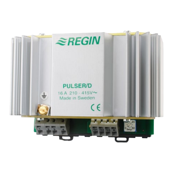
PULSER/D
i
Read this instruction before installation
and wiring of the product
Consult documentation in all cases where this symbol
is used, in order to find out the nature of the potential
hazards and any actions to be taken
Triac controller for proportional control
of electric heating
PULSER/D is a proportional controller for electric heating with auto-
matic voltage adjustment. PULSER/D pulses the whole load On - Off.
The ratio between On-time and Off-time is varied 0 - 100% to suit the
prevailing heat demand. The current is always switched at zero phase
angle to prevent RFI.
PULSER/D is only intended for electric heating control. The control
principle makes it unsuitable for motor- or lighting control.
PULSER/D cannot control 3-phase loads.
PULSER/D is intended for DIN-rail mounting.
Mount PULSER/D on a DIN-rail in a cabinet or other enclosure.
Mount PULSER/D vertically with the text right side up.
Protection class:
IP20
Ambient temperature:
0 - 40°C
PULSER/D emits approx. 20W of heat which must be dissipated.
Wiring
Supply voltage
Terminals 1 and 2. Not polarity sensitive.
Supply voltage: 200 - 415V AC, 50 - 60 Hz with automatic voltage
adjustment.
Maximum current 16A.
1
2
3
4
G1G2 G3 K
Figure 1: Wiring of supply voltage and load
The supply voltage to PULSER/D should be wired via an allpole
switch with a minimum contact gap of 3mm. PULSER/D must be earthed.
Load
Terminals 3 and 4.
Resistive single- or two-phase heater.
Maximum load:
3680W at 230V (16A)
6400W at 400V (16A)
Minimum load:
230W at 230V (1A)
400W at 400V (1A)
External sensor and setpoint (figures 2-6)
Terminals G1, G2 and G3. Not polarity sensitive.
The choice of terminals is determined by whether the internal set-
point is to be used or not.
If the internal setpoint is to be used the sensor is to be connected to
terminals G1 and G3.
If an external setpoint device is used, use terminals G1 and G2.
The PULSER/D sensors have high potential compared to neutral
and earth (>200V). Thus, wiring and installation of the sensors must com-
ply with local codes for line voltage installations.
PULSER/D
G1 G2 G3
TG-R530
1
2
Figure 2: Wiring of room sensor TG-R530 when using
internal setpoint
G1 G2 G3
TG-R430
1
3
Figure 3: Wiring of room sensor TG-430 used as external
setpoint and sensor
G1 G2 G3
TG-K3xx
TG-G1xx
Figure 4: Wiring of floor or duct sensor when using
internal setpoint
TG-K3xx
G1 G2
G3
TG-R4xx
TG-G1xx
2
3
Figure 5: Wiring of external separate sensor when using TG-R4xx
as external setpoint
TG-K3xx
TBI-xx
G1 G2G3
TG-G1xx
1
2
Figure 6: Wiring of external, separate sensor when using
potentiometer TBI-xx as external setpoint
1
Advertisement
Table of Contents

Related Manuals for Regin PULSER/D


Summary of Contents for Regin PULSER/D
- Page 1 The supply voltage to PULSER/D should be wired via an allpole TG-G1xx switch with a minimum contact gap of 3mm. PULSER/D must be earthed. Consult documentation in all cases where this symbol is used, in order to find out the nature of the potential...
- Page 2 Switch on power again. For rapid temperature changes e.g. supply air control PULSER/D will PULSER/D should not give out any power at all and the LED should act as a PI controller with a proportional band of 20K and a reset time be extinguished.
- Page 3 Figur 3: Inkoppling vid rumsreglering med TG-R430 som gör att den inte kan användas till motor- eller belysningsstyrning. Matningen till PULSER/D skall ske via en allpolig brytare med extern givare och börvärdesinställning PULSER/D kan inte användas för styrning av 3-fas värmare.
- Page 4 Slå av matningsspänningen och kortslut mellan givaringångarna Figur 7: Inkoppling av nattsänkningsfunktion. G1 - G2 eller G1 - G3 . Slå på matningsspänningen igen. PULSER/D skall inte ge någon uteffekt alls. Lysdioden skall vara släckt. Kontrol- Reglerprincip lera med tång amperemeter att ingen ström går ut till värmaren.
- Page 5 PULSER/D impulssteuert die angeschlossene Leistung Ein- und Abb. 1: Anschluß der Versorgungs spannung und Belastung. Ab. PULSER/D paßt die mittlere Leistung an den erforderlichen Leistungsbedarf an, indem er das Verhältnis zwischen Einschalt- Abb. 3: Umschalter und Anschluß an exter nem Fühler und internem Sollwert.
- Page 6 Stellung belassen wie vorher. Versorgungsspannung Installation erneut einschalten. Der PULSER/D soll keine überhaupt keine Le PULSER/D doit êntre fixé sur un rail DIN dans une armoire électri- Ausgangsleistung abgeben. Die Leuchtdiode soll nicht leuchten. que. Il doit êntre monté...
- Page 7 Fig 1: Branchement alimentation et batterie Le PULSER/D module les temps de fonctionnement et les temps d’arrêt. Le PULSER/D ajuste la puissance de sortie en foncion de la Fig 3: Emplacement de la sonde TG-R430 avec point de puissance demandée et le ratio entre le temps de fonctionnement et consigne sur la sonde le temps d’arrêt.
- Page 8 Vérifier que vous avec du courant sur les bornes 1 et 2. Si oui, Contact le PULSER/D est probablement fautif. Si la LED est allumée et Regin FRANCE, 32 rue Delizy, 93500 Pantin le courant ne passe pas vers la battereie. Vérifier votre batterie.
Need help?
Do you have a question about the PULSER/D and is the answer not in the manual?
Questions and answers