
Related Manuals for Hach PHOSPHAX sc LR


Summary of Contents for Hach PHOSPHAX sc LR
- Page 1 DOC023.53.90627 PHOSPHAX sc LR, PHOSPHAX indoor sc LR User Manual 08/2018, Edition 1...
-
Page 3: Table Of Contents
Table of Contents Section 1 Specifications ........................3 1.1 Sample requirements........................4 1.2 Interferences..........................4 Section 2 General information ......................5 2.1 Safety information........................5 2.1.1 Use of hazard information....................5 2.1.2 Precautionary labels......................5 2.1.3 Chemical and biological safety.................... 6 2.1.4 Certification......................... - Page 4 Table of Contents Section 5 Maintenance ........................45 5.1 Maintenance schedule....................... 45 5.2 Examine for damage........................45 5.3 Examine the tubing and fittings....................45 5.4 Clean the instrument........................46 5.5 Clean spills..........................46 5.6 Replace the reagents......................... 46 5.7 Replace the air filter pads......................46 5.8 Replace the pump head for air pump (piston pump)..............
-
Page 5: Section 1 Specifications
Specifications are subject to change without notice. Specification Details Dimensions (W x H x D) PHOSPHAX sc LR: 540 × 720 × 390 mm (21.25 × 28.35 × 15.35 in.) PHOSPHAX indoor sc LR: 540 × 720 × 370 mm (21.25 × 28.35 × 14.5 in.) Enclosure Enclosure rating: PHOSPHAX sc LR, IP55;... -
Page 6: Sample Requirements
Specifications 1.1 Sample requirements The water from the sample source(s) must agree with the specifications that follow. Specification Description Sample flow rate 1.0 to 20.0 L/h Sample pressure With continuous sample preparation: –30 mbar to +50 mbar at overflow vessel. Sample temperature 4 to 45 °C (39 to 113 °F) Sample quality... -
Page 7: Section 2 General Information
Section 2 General information In no event will the manufacturer be liable for direct, indirect, special, incidental or consequential damages resulting from any defect or omission in this manual. The manufacturer reserves the right to make changes in this manual and the products it describes at any time, without notice or obligation. -
Page 8: Chemical And Biological Safety
General information This symbol indicates the need for protective eye wear. This symbol indicates that the marked item requires a protective earth connection. If the instrument is not supplied with a ground plug on a cord, make the protective earth connection to the protective conductor terminal. This symbol, when noted on the product, identifies the location of a fuse or current limiting device. -
Page 9: Product Overview
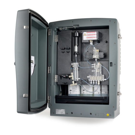
4. Reposition the receiving antenna for the device receiving the interference. 5. Try combinations of the above. 2.2 Product overview The PHOSPHAX sc LR is a one-channel analyzer that measures ortho-phosphate ions 3— ) in waste water and surface water. The analyzer does not measure diphosphates or polyphosphates. - Page 10 General information Figure 1 Product overview 1 PHOSPHAX sc LR 6 Piston pump 11 Valve block 2 Status indicator light 7 Safety glass 12 Overflow vessel 3 Door lock 8 Reagent pumps 13 Transport lock 4 PHOSPHAX indoor sc LR...
-
Page 11: Status Indicator Light
General information 2.2.1 Status indicator light The status indicator light shows the analyzer condition. Refer to Table Table 2 Status indicator description Color Status Green The analyzer is in operation with no warnings, errors or reminders. Orange The analyzer is in operation with active warnings or reminders. The analyzer is not in operation because of an error condition. - Page 12 General information Figure 2 Product components 1 PHOSPHAX sc LR 10 Angle bracket, wall mount 19 Hose plug (2x) 2 Door keys 11 Console bracket, wall mount 20 Sealing disc 3 Tubing plug (3x) 12 Blind plug 21 Blind plug...
-
Page 13: Section 3 Installation
Section 3 Installation D A N G E R Multiple hazards. Only qualified personnel must conduct the tasks described in this section of the document. 3.1 Installation guidelines Install the instrument: • As near the sample source as possible to decrease analysis delay •... - Page 14 Installation Figure 3 Mounting dimensions...
-
Page 15: Open The Enclosure
Installation 3.2.2 Open the enclosure C A U T I O N Personal injury hazard. The object is heavy. Make sure that the instrument is securely attached to a wall, table or floor for a safe operation. C A U T I O N Electrical shock hazard. -
Page 16: Remove The Transport Lock
Installation Use the door hook to open the door safely. Refer to the illustrated steps that follow. Figure 4 Open the door As an alternative, remove the door for better access during installation and maintenance procedures. Refer to Figure 5. Make sure to install and close the door before operation. Figure 5 Remove the door 3.2.3 Remove the transport lock Remove the transport lock from the analyzer. -
Page 17: Electrical Connectors And Plumbing Access Ports
Installation 3.3 Electrical connectors and plumbing access ports Figure 6 shows the electrical connectors and fittings on the instrument. Use the tubing plug to put tubing or cables through the analyzer access ports. To keep the environmental rating of the enclosure, make sure that there is a sealing plug in the access ports that are not used. -
Page 18: Drain Line Guidelines
Installation • Make sure that the samples are sufficiently mixed. • Make sure that all chemical reactions are complete. 3.4.2 Drain line guidelines Correct installation of the drain lines is important to make sure that all of the liquid is removed from the instrument. - Page 19 Installation Table 3 System configuration options (continued) Location Filtration Drain Number of Number of Plumbing option analyzers parameters Outdoor Continuous Heated Refer to Plumbing one sample feed outdoor analyzer with continuous sample feed on page 21. 2 heated Refer to Plumbing two outdoor analyzers with continuous sample feed...
-
Page 20: Plumbing One Outdoor Analyzer
Installation Table 3 System configuration options (continued) Location Filtration Drain Number of Number of Plumbing option analyzers parameters Indoor Continuous Unheated 1 Refer to Plumbing one sample feed indoor analyzer with continuous sample feed on page 27. Unheated 2 Refer to Plumbing two indoor analyzers with continuous sample feed... -
Page 21: Plumbing Two Outdoor Analyzers
Installation Figure 7 Plumbing one outdoor analyzer 1 Heated drain sample lines (not used) 3 FILTRAX sample line 2 Heated drain 3.5.2 Plumbing two outdoor analyzers This system configuration option uses two sc analyzers with the FILTRAX instrument for the sample line. The sample from the FILTRAX goes to the first analyzer, which must change to a 2-parameter configuration. - Page 22 Installation 10. Change the analyzer to a two-parameter configuration. Refer to Two-parameter configuration on page 29. Install the second sc analyzer as follows: 11. Use a tubing plug to put the heated drain hose from first analyzer through one access port of second analyzer.
-
Page 23: Plumbing One Outdoor Analyzer With Continuous Sample Feed
Installation Figure 8 Plumbing two outdoor analyzers 1 PHOSPHAX sc LR analyzer 6 T-fitting from first analyzer 2 Heated drain sample lines (not used) 7 Heated drain 3 AMTAX sc analyzer 8 Heated drain from first analyzer 4 Sample line to second analyzer (overflow vessel tube) -
Page 24: Plumbing Two Outdoor Analyzers With Continuous Sample Feed
Installation 4. Use a tubing plug to put the heated drain hose through the analyzer access port. Note: The two samples lines of the heated drain hose are not used. 5. Connect the heated drain connections. Refer to Connect the optional heated drain on page 34. - Page 25 Installation 4. Use the sealing plug to close access ports that are not used. 5. Connect the heated drain connections. Refer to Connect the optional heated drain on page 34. 6. Remove the pre-installed drain tube attached to the valve block. Remove the T-fitting from the drain tube.
-
Page 26: Plumbing One Indoor Analyzer
Installation Figure 10 Plumbing two outdoor analyzers with continuous sample feed 1 PHOSPHAX sc LR analyzer 6 T-fitting from first analyzer 2 Heated drain sample lines (not used) 7 Heated drain 3 AMTAX sc analyzer 8 Heated drain from first analyzer... -
Page 27: Plumbing Two Indoor Analyzers
Installation 4. Use a sealing plug to put the drain tube through the analyzer access port. Note: Tubes can be pushed through prepared holes on the sealing plug. 5. Connect the drain tube to the T-fitting. 6. Use the sealing plug to close access ports that are not used. 7. - Page 28 12. Connect the drain tube to the T-fitting. 13. Connect the sample line to the bottom inlet on the overflow vessel. Figure 12 Plumbing two indoor analyzers 1 PHOSPHAX sc LR analyzer 4 Second analyzer drain 2 AMTAX sc analyzer...
-
Page 29: Plumbing One Indoor Analyzer With Continuous Sample Feed
Installation 3.5.7 Plumbing one indoor analyzer with continuous sample feed This configuration option uses one indoor sc analyzer and one sample preparation unit that supplies a continuous sample stream. The waste of the analyzer is released into an open drain. Do the steps that follow to install one indoor analyzer with continuous sample feed. - Page 30 Installation Do the steps that follow to install two indoor analyzers with continuous sample feed. Refer Figure 1. Install the sample preparation unit. Install the first sc analyzer as follows: 2. Use a sealing plug to put the sample line from the sample preparation unit through the analyzer access port.
-
Page 31: Two-Parameter Configuration
(i.e., ammonium measured by the AMTAX sc analyzer). Change the Phosphax sc LR to a 2-parameter configuration. Connect the sample line to the overflow vessel. Remove the T-fitting from the first analyzer drain and use the T-fitting to connect the drain tube from the first analyzer to the second analyzer. - Page 32 Installation...
- Page 33 Installation...
-
Page 34: Install The Collecting Tray And Humidity Sensor
Installation 3.6 Install the collecting tray and humidity sensor D A N G E R Electrocution hazard. Always remove power to the instrument before making electrical connections. Refer to the illustrated steps that follow. 3.7 Install the reagents W A R N I N G Chemical exposure hazard. - Page 35 Installation The analyzer uses four chemicals: Reagent A, Reagent B, Standard Solution S and Cleaning Solution C. The solutions are prepared at the factory and ready to install. Do the steps that follow and refer to Figure 15 to install or replace the chemicals. 1.
-
Page 36: Electrical Installation
Installation 3.8 Electrical installation 3.8.1 Electrostatic discharge (ESD) considerations N O T I C E Potential Instrument Damage. Delicate internal electronic components can be damaged by static electricity, resulting in degraded performance or eventual failure. Refer to the steps in this procedure to prevent ESD damage to the instrument: •... -
Page 37: Supply Power To The Analyzer
Installation Figure 16 Heated drain connections 3.8.3 Supply power to the analyzer D A N G E R Electrocution hazard. Protective Earth Ground (PE) connection is required. D A N G E R Electrical shock and fire hazards. Make sure to identify the local disconnect clearly for the conduit installation. - Page 38 Installation W A R N I N G Electrical shock and fire hazards. Make sure that the user-supplied power cord and non‐ locking plug meet the applicable country code requirements. N O T I C E Install the device in a location and position that gives easy access to the disconnect device and its operation.
-
Page 39: Close The Analyzer
Installation Figure 17 Connect the analyzer to the SC Controller 3.9 Close the analyzer N O T I C E Close the analyzer door to keep the environmental rating of the enclosure. N O T I C E Make sure that the lock is in the open position before closing the door or damage to the enclosure can occur. - Page 40 Installation Figure 18 Close the analyzer door...
-
Page 41: Section 4 Operation
1. Make sure that the analyzer is registered in the SC Controller. Refer to the controller documentation for instructions. 2. In the SENSOR SETUP menu, select PHOSPHAX sc LR > DIAG/TEST > MAINTENANCE > SELECT PROCESS. 3. Select PREPUMP ALL. -
Page 42: Configure The Calibration Settings
Sets the configuration to the factory defaults. 4.4 Configure the calibration settings Select the calibration curve, calibration interval, output behavior during calibration and more. 1. Push Menu. 2. Select SENSOR SETUP > PHOSPHAX sc LR > CALIBRATION. 3. Select an option. Option Description START Starts a manual calibration. -
Page 43: Configure The Maintenance Settings
4.6 Configure the maintenance settings Select service mode, menu-guided maintenance, reagent counters, output behavior during maintenance and more. 1. Push Menu. 2. Select SENSOR SETUP > PHOSPHAX sc LR > DIAG/TEST > MAINTENANCE. 3. Select an option. Option Description DELETE ERROR Reset all error messages. -
Page 44: System Configuration
1. Select PHOSPHAX sc LR > CALIBRATION > SET INTERVAL to configure an automatic calibration interval. 2. Select PHOSPHAX sc LR > CALIBRATION > START to start a manual calibration. The calibration is postponed when the instrument was switched on for less than 1 hour, the temperature is outside of the specified range or the current measured value is >... - Page 45 Operation 1. Select PHOSPHAX sc LR > CONFIGURE > CLEANING > SET INTERVAL to configure an automatic cleaning interval. Refer to Configure the instrument on page 39. 2. Select PHOSPHAX sc LR > DIAG/TEST > MAINTENANCE > SELECT PROCESS >...
- Page 46 Operation...
-
Page 47: Section 5 Maintenance
Section 5 Maintenance W A R N I N G Multiple hazards. Only qualified personnel must conduct the tasks described in this section of the document. C A U T I O N Chemical exposure hazard. Obey laboratory safety procedures and wear all of the personal protective equipment appropriate to the chemicals that are handled. -
Page 48: Clean The Instrument
After a reagent is replaced, reset the related counter. Reset the counter for Reagent B schedules a calibration which takes 40 minutes to complete. 1. Select PHOSPHAX sc LR > DIAG/TEST > MAINTENANCE > COUNTERS and push RESET. 5.7 Replace the air filter pads W A R N I N G Pinch hazard. - Page 49 Do the steps that follow to stop the fan and replace the air filter pads: 1. Push Menu, then select SENSOR SETUP > PHOSPHAX sc LR. 2. Select DIAG/TEST > MAINTENANCE > SELECT PROCESS > CHANGE AIRFILTER and push Enter.
-
Page 50: Replace The Pump Head For Air Pump (Piston Pump)
W A R N I N G Pinch hazard. Parts that move can pinch and cause injury. Do not touch moving parts. 1. Push Menu, then select SENSOR SETUP > PHOSPHAX sc LR. 2. Select DIAG/TEST > MAINTENANCE > SELECT PROCESS > CHANGE PISTON, then push Enter. -
Page 51: Do A Leakage Test
After the pump head replacement for the air pump, do a leakage test. 1. Push Menu, then select SENSOR SETUP > PHOSPHAX sc LR. 2. Select DIAG/TEST > MAINTENANCE > SELECT PROCESS > LEAK TIGHT AIR-P and push Enter. -
Page 52: Replace The Fuses
1. Put the instrument in service mode. For use with Filtrax, refer to the documentation supplied. 2. Push Menu. 3. Select SENSOR SETUP > PHOSPHAX sc LR > DIAG/TEST > MAINTENANCE > SELECT PROCESS then push SERVICE MODE. 4. On the overflow vessel, unscrew the fitting of the sample tube that connects the overflow vessel and the valve block. -
Page 53: Validation With Applicable Laboratory Measurement (Cuvette Test)
Maintenance 8. Reinstall the tube in the overflow vessel. Make sure to push the fitting into the overflow vessel as far as possible, then carefully screw the fitting into the overflow vessel. 9. Start the measurement mode or hold service mode. Figure 20 Prepare the analyzer for a validation check 5.11.2 Validation with applicable laboratory measurement (cuvette test) C A U T I O N... - Page 54 1. Stop the sample stream. For use with Filtrax, refer to the documentation supplied. 2. Put the instrument in service mode. Push Menu. 3. Select SENSOR SETUP > PHOSPHAX sc LR > DIAG/TEST > MAINTENANCE > SELECT PROCESS then push SERVICE MODE.
-
Page 55: Put The Analyzer In Shutdown Mode
Maintenance Figure 21 Remove T-fitting 5.12 Put the analyzer in shutdown mode No special measures are necessary to remove the analyzer from operation for a short period (a maximum of 2 days in frost-free ambient conditions). Note: If the power supply to the controller is interrupted, frost damage may occur. Make sure that the instrument and tubing cannot freeze. - Page 56 1. Remove the tubing from the reagent and cleaning solutions bottles and put the tubing in distilled water. 2. On the controller menu, select SENSOR SETUP > PHOSPHAX sc LR > DIAG/TEST > MAINTENANCE > SELECT PROCESS > FLUSHING to start a cleaning cycle with distilled water.
-
Page 57: Section 6 Troubleshooting
Refer to Status indicator light on page 9. Reminders Reminders show on the controller display. To see all of the reminders, push Menu then select DIAGNOSTICS > PHOSPHAX sc LR > REMINDER LIST. Message Possible cause Solution REAGENT A LEVEL Level of reagent A is below the reminder level. - Page 58 Errors Errors show on the controller display. To see all of the errors, push Menu then select DIAGNOSTICS > PHOSPHAX sc LR > ERROR LIST. Message Possible cause Solution TEMP < 0°C/32°F? The analyzer temperature is less than 4 °C...
- Page 59 Troubleshooting Message Possible cause Solution DRAIN BLOCKED The drain line is blocked. Clean the drain line. SAMPLE The amount of sample is not sufficient. Examine the sample delivery unit. Make sure that the sample line has no negative pressure. Examine the tightness of the piston pump.
- Page 60 Troubleshooting...
-
Page 61: Section 7 Replacement Parts And Accessories
Section 7 Replacement parts and accessories W A R N I N G Personal injury hazard. Use of non-approved parts may cause personal injury, damage to the instrument or equipment malfunction. The replacement parts in this section are approved by the manufacturer. Note: Product and Article numbers may vary for some selling regions. - Page 62 Replacement parts and accessories Mounting hardware (continued) Description Item no. Stand mounting, sc analyzer with controller LZY286 Stand mounting, sc analyzer without controller LZY287 Reagents and standard solutions Description Item no. Reagent Set A/B (contains LCW956 + LCW957) LCW955 Reagent A LCW956 Reagent B LCW957...
- Page 64 Tel. +49 (0) 2 11 52 88-320 SWITZERLAND Fax (970) 669-2932 Fax +49 (0) 2 11 52 88-210 Tel. +41 22 594 6400 orders@hach.com info-de@hach.com Fax +41 22 594 6499 www.hach.com www.de.hach.com © Hach Company/Hach Lange GmbH, 2018. All rights reserved. Printed in Germany. *DOC023.53.90627*...
Need help?
Do you have a question about the PHOSPHAX sc LR and is the answer not in the manual?
Questions and answers