Table of Contents
Advertisement
Quick Links
Advertisement
Table of Contents

Related Manuals for Banner iVu TG


Summary of Contents for Banner iVu TG
- Page 1 TG Quick Start Guide Rev. C 10/3/2011 143367...
-
Page 2: Table Of Contents
Contents Introduction ...............................3 Installing and Connecting the Sensor ....................4 Cable Connections for the iVu TG with Integrated Display ....................5 Cable Connections for the iVu TG with a Remote Display ....................5 Demo Mode ..............................7 Sensor Types ..................................7 Selecting a Sensor Type ..............................7... -
Page 3: Introduction
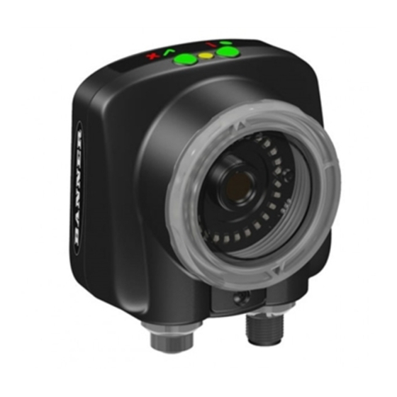
Introduction The iVu TG Image Sensor is used to monitor labels, parts, and packaging for type, size, orientation, shape, and location. The sensor has an integrated color touch screen display making installation, setup and configuration easy without requiring a PC. -
Page 4: Installing And Connecting The Sensor
TG Quick Start Guide Installing and Connecting the Sensor The iVu TG sensor requires a bracket for mounting. Three brackets are available from Ban- ner. The brackets allow the sensor to be mounted either perpendicular to the part or at an adjustable angle. -
Page 5: Cable Connections For The Ivu Tg With Integrated Display
NOTE: Microlens models show, C-Mount model connections are identical. Cable Connections for the iVu TG with a Remote Display The cable connections on the iVu sensor are shown below, and power I/O connections (B) are defined in the Power I/O Connections table below. - Page 6 TG Quick Start Guide Power I/O Connections Pin # Wire Color Description Direction Brown 10-30V dc Input Blue Common (Signal Ground) Input Pink External Trigger Input Gray Remote Teach Input White Output 1 Output Ready Output Yellow Strobe Out (5V dc only)
-
Page 7: Demo Mode
Demo Mode The first time you power up the iVu TG sensor, it starts in Demo Mode. Demo Mode uses stored images and inspection parameters that demonstrate how the sensor is set up without having to worry about focus, lighting, or triggers. In this mode, you can learn how to make adjustments working with the three sensor types while observing how the adjustments affect the sensor results. -
Page 8: Acquiring A Good Image
• Capture the shape and form of the target object with lighting that optimizes its contrast and separates it from the background. Depending on the target, this may mean the integral ring light is not the best choice and other Banner lights should be consid- ered. - Page 9 TG Quick Start Guide For Micro-lens Models Only: 1. Use the supplied 1/16" hex key to loosen the Focusing Window locking screw (D), then adjust focus on the iVu Series sensor using the clear Focusing Window (B). 2. Adjust focus while monitoring the focus number. To ensure the best image, adjust the focus until the Focus Number peaks.
- Page 10 TG Quick Start Guide For C-Mount Models Only: 1. Remove the Lens Enclosure 2. Adjust focus while monitoring the focus number. To ensure the best image, adjust the focus until the Focus Number peaks. 3. Replace the Lens Enclosure on the camera.
-
Page 11: Configuring An Area Sensor
Configuring an Area Sensor The flow chart at left provides an overview of the steps to setting up an inspection on the iVu TG sensor as an Area sensor. Start 1. Make sure you have a good part to use for the inspection setup. Normally, the part being in-... -
Page 12: Configuring A Blemish Sensor
TG Quick Start Guide Configuring a Blemish Sensor The flow chart at left provides an overview of the steps to setting up an inspection on the iVu TG sensor as a Blemish sensor. Start 1. Make sure you have a good part to use for the inspection setup. Normally, the part being inspected is centered in the field of view with the feature of interest surrounded by the Re- gion of Interest (ROI), the blue rectangle. -
Page 13: Configuring A Match Sensor
Configuring a Match Sensor The flow chart at left provides an overview of the steps to setting up an inspection on the iVu TG sensor as a Match sensor. Start 1. Make sure you use a good part for the inspection setup. Normally, the part will be centered in the field of view with the feature of interest surrounded by the Region of Interest (ROI), a blue rectangle. -
Page 14: Adjusting For Motion
TG Quick Start Guide Adjusting for Motion When the sensor is configured as an Area or Blemish sensor, it can automatically adjust for motion of inspected parts in the field of view. Motion parameter settings are enabled by going to Main Menu > Sensor > Motion . With Motion enabled, a new menu is available in the Main Menu >...
Need help?
Do you have a question about the iVu TG and is the answer not in the manual?
Questions and answers