Banner iVu Plus BCR Instruction Manual
Hide thumbs
Also See for iVu Plus BCR:
- Instruction manual (28 pages) ,
- User manual (155 pages) ,
- Quick start manual (22 pages)

Related Manuals for Banner iVu Plus BCR


Summary of Contents for Banner iVu Plus BCR
- Page 1 Plus BCR Instruction Manual Original Instructions B_3084220 Rev. C 18 March 2014...
-
Page 2: Table Of Contents
Plus BCR User's Manual Contents 1 Overview of the Sensor ....................4 1.1 Installation ..........................4 1.1.1 Components ........................4 1.1.2 Installing and Connecting the Sensor ................6 1.1.3 Cable Connections ......................8 1.1.4 iVu Trigger, Remote Teach, and I/O Waveforms ..............9... - Page 3 Plus BCR User's Manual 5.5 Command Channel Primer ....................... 65 5.5.1 Command Channel Commands ..................65 5.5.2 Conventions Used for Examples ..................66 5.5.3 Examples ........................67 5.5.4 Command Channel Reference ..................68 5.5.5 Command Channel Command Status Register ..............73 5.5.6 Command Channel Error Codes...
-
Page 4: Overview Of The Sensor
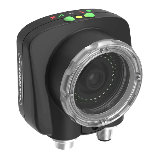
1 Overview of the Sensor The iVu Plus BCR sensor reads a wide variety of barcodes. The package consists of sensor, lighting, lens, and display. Cables and mounting brackets can be ordered for each application. Additionally, other lenses, filters, and external lights are available. - Page 5 Although the Remote Display is not required for normal sensor operation, it is needed to set up the sensor and to monitor inspections. If an integrated ring light is not used, another light source is needed. Various lights are available from Banner. Operating ®...
-
Page 6: Installing And Connecting The Sensor
1.1.2 Installing and Connecting the Sensor The iVu Plus BCR sensor requires a bracket for mounting. Three brackets are available from Banner. The brackets allow the sensor to be mounted either perpendicular to the part or at an adjustable angle. - Page 7 Plus BCR User's Manual NOTE: The light/lens assembly may include an integrated ring light or a blank disk if an integrated ring light is not used. Be careful that the light/lens assembly does not pull out when removing the Focusing Window. Give a slight tug on the Focusing Window when you think you've unscrewed it far enough.
-
Page 8: Cable Connections
Plus BCR User's Manual CAUTION: Electrostatic Discharge Avoid the damage that electrostatic discharge (ESD) can cause to the Sensor. Always use a proven method for preventing electrostatic discharge when installing a lens or attaching a cable. 1.1.3 Cable Connections... -
Page 9: Ivu Trigger, Remote Teach, And I/O Waveforms
Plus BCR User's Manual Remote Display Connector Power I/O Connector USB Connector Ethernet Connector NOTE: Micro video lens model shown, C-Mount model connections are identical. Power I/O Connections Pin # Wire Color Description Direction White Output 1 Output Brown... - Page 10 The sensor triggers from high to low, and Remote Teach behaves electrically like trigger. NOTE: If the device used to trigger or remote teach the iVu Plus BCR is a sinking device, these are the options regarding the use of a pull-up resistor: Option 1: Put a pull-up resistor, rated approximately 1k ohm, between the sensor's positive (+) voltage and the sensor's input as shown below.
-
Page 11: Live Mode Overview
1.2 Live Mode Overview The iVu Plus BCR can be configured to evaluate one or more of the supported barcode types and can look for a specific number of barcodes from 1 to 10. The barcode types are selected on the integrated touch screen by accessing Main Menu >... -
Page 12: Compare Data
Plus to match the settings of the external device. The iVu Plus BCR RS-232 port or ethernet port can be used to output barcode data to other applications. To access the Data Export screen, go to Main Menu > System > Communications > Data Export. The user can enable or disable this feature. -
Page 13: Remote Teach
Plus BCR User's Manual Type of Data to Export: Serial Port Settings: • Pass/Fail Output • Baud Rates • Inspection Name • Start Bits • Barcode Count • Stop Bits • Data Length • Data Bits • Symbol Type •... -
Page 14: Home Screen
Plus BCR User's Manual 2 Home Screen The Home screen on the iVu Series sensor display is used to monitor inspections and to configure the sensor. Normally, the part being inspected is centered on the screen. Display Help Button... -
Page 15: Inspection Statistics
Plus BCR User's Manual Click the icon in the upper-left of the screen to hide annotations. 2.1.2 Inspection Statistics To access the Inspection Statistics, click the Display mode icon The Inspection Statistic mode has three pages: • History •... - Page 16 Plus BCR User's Manual Barcode Viewer To view detailed information about a particular barcode, click the arrow next to the Barcode # to access the Barcode Viewer screen. If Data Compare is disabled, The Barcode Viewer screen shows a single text box indicating the index number of the barcode and the data the sensor is reading.
- Page 17 Plus BCR User's Manual...
-
Page 18: Main Menu Reference
Plus BCR User's Manual 3 Main Menu Reference 3.1 Main Menu The Main Menu has four sections. Inspection—to modify inspection settings. Imager—to run the Auto Exposure routine and to make adjustments to functions like exposure, gain, and strobe. System—to set output signals, communication channel parameters and to manage the device. -
Page 19: Mode
Plus BCR User's Manual The System menu icon is on the Main Menu, and is used to manage the sensor. The System menu provides for selecting Sensor Mode, updating sensor firmware, backing up and restoring sensor Configuration, and other general system-level operations. -
Page 20: System Information
Plus BCR User's Manual Save to USB Main Menu > System > Configuration > Save to USB The Save to USB screen allows the sensor Configuration to be saved to a USB flash drive. The saved configuration information can be used as a backup or as a way to clone configuration information for other sensors. -
Page 21: Lock Device
Plus BCR User's Manual • Model Number • Device Name Click the right-arrow next to the Sensor Name field to display a software keyboard that allows you to change the Sensor Name. 3.2.4 Lock device Main Menu > System > Lock device This option provides for locking the sensor to prevent accidental modification of settings. - Page 22 Plus BCR User's Manual Ethernet I/O Status Main Menu > System > Communications > Ethernet I/O > Status The Ethernet I/O Status screen can be used to verify that the Ethernet wiring has been correctly set up. In addition to determining if the link has been established, incoming and outgoing traffic can be monitored.
- Page 23 Plus BCR User's Manual Industrial Ethernet Main Menu > System > Communications > Industrial Ethernet The iVuPlus device can be controlled or monitored over Industrial Ethernet using Ethernet/IP, Modbus/TCP or PCCC protocols. This document will help you to set up the iVu Plus in the desired configuration and provide you with information you will need to connect to the master device (PLC, HMI, etc.).
- Page 24 Plus BCR User's Manual Delimiters Main Menu > System > Communications > Command Channel > Delimiters In the Delimiters screen, there are three delimiter options that you can set: • Field Delimiter, which determines what is used to separate data that the sensor is sending out to a remote device.
- Page 25 Plus BCR User's Manual Data To Export Main Menu > System > Communications > Data Export > Data To Export The options in the Data To Export screen are used to determine what barcode data is exported via the serial port.
-
Page 26: Discrete I/O
Plus BCR User's Manual During the Data and Image export operation, the sensor's output channels might become full. This can occur if the sensor is producing export data (frames) faster than the data can be exported from the device or faster than the client is reading the channel export data (due to bandwidth limitations). - Page 27 Plus BCR User's Manual Input Polarity Main Menu > System > Discrete I/O > Input Polarity The iVu has two input signals—Trigger and Remote Teach. Both of these signals are edge sensitive. The operation of these signals is dependent on the Input Polarity setting.
-
Page 28: Display Settings
Plus BCR User's Manual Output 1 Main Menu > System > Discrete I/O > Output 1 Output 1 can be configured for Pass, Fail, Read, No Read, Match, No Match, Missed Trigger, or System Error. • A Read condition is when the configured number of barcodes are found in a scan. These barcodes must be error- free. -
Page 29: Reboot Sensor
Plus BCR User's Manual Fail Hold Time Main Menu > System > Display Settings > Fail Hold Time The Fail Hold Time determines how long a failed image is displayed on the LCD so that you can see what failed. The sensor will continue to process any triggers and the inspection will continue normally. -
Page 30: Imager Menu
The Firmware Update screen is used to load the latest sensor firmware. The Firmware Update screen lists the firmware versions it finds in the BANNER\FIRMWARE folder on the USB flash drive. When you receive a firmware update from Banner Engineering, be sure to put it in the BANNER\FIRMWARE folder on the USB flash drive. -
Page 31: Gain
Plus BCR User's Manual 3.3.3 Gain Main Menu > Imager > Gain Gain is an electronic boost to the image signal. Increasing Gain by using the '-' and '+' keys or moving the slider to the right increases image brightness without increasing exposure time. Note that Gain brightens both the light pixels and dark pixels and may reduce the image quality. - Page 32 Plus BCR User's Manual Continuous Mode In Continuous mode, the sensor uses internal timing to continuously capture images. For each captured image, the sensor scans through the configured barcode types looking for the specified number of barcodes. If the specified number of barcodes is found, a Read event occurs.
-
Page 33: Focus
Plus BCR User's Manual NOTE: A No Read condition will not occur in External - Gated mode while the external trigger is active. Command Mode In Command mode, the sensor captures images when Trigger commands are received. The various trigger command modes described above can also be set through a command channel. -
Page 34: Strobe
Plus BCR User's Manual 3.3.6 Strobe Main Menu > Imager > Strobe The Internal Strobe configures the operation of the integrated ring light. The External Strobe configures the operation of an external light. External Main Menu > Imager > Strobe > External The External Strobe is a 5V output that can be used for an external light. -
Page 35: Fov (Field Of View)
Plus BCR User's Manual The Internal Strobe setting configures the operation of the integrated ring light. Strobe options are Always ON, Always OFF, or Exposure Based. If Exposure Based is selected, then the ring light is on during the time the sensor is capturing an image. -
Page 36: Inspection Menu
Plus BCR User's Manual Modify FOV Main Menu > Imager > FOV > Modify FOV Use this option to reduce or alter the size of the FOV. 3.4 Inspection Menu Main Menu > Inspection The Inspection menu icon is located on the Main Menu. The Inspection Menu provides options to set inspection parameters on currently running inspection and manage stored inspections. - Page 37 Plus BCR User's Manual DataMatrix Settings Decoder Mode The Decoder Mode determines which decode algorithm to use and how imperfections in barcode images are handled. When you select Fast from the drop-down list, the sensor uses an algorithm that is tailored for speed. The algorithm does NOT correct for barcode image imperfections.
- Page 38 Plus BCR User's Manual Use filters to improve decode rates in conditions in which the barcodes are blurred or have nonuniform module sizes. Select one or more Out‐of‐focus filters to improve the decode rate of out‐of-focus barcodes. Select the Non Uniform filter to improve the decode rate of barcodes with non‐uniformly sized data modules.
- Page 39 Plus BCR User's Manual Checksum Verify When checksum is enabled, the sensor uses a checksum to verify the integrity of the barcode being read. Relaxed Quietzone The Quietzone is a blank margin on either side of a barcode that indicates where the barcode begins and ends. If this Quietzone isn't big enough, the sensor can have trouble decoding the barcode.
- Page 40 Plus BCR User's Manual Relaxed Quietzone The Quietzone is a blank margin on either side of a barcode that indicates where the barcode begins and ends. If this Quietzone isn't big enough, the sensor can have trouble decoding the barcode. Enabling Relaxed Quietzone creates a greater tolerance with respect to the quiet zone required before and after the barcode.
- Page 41 Plus BCR User's Manual Compare Data The Compare Data screen allows you to specify data against which you can compare a read barcode. Note that, if the Barcode Count is greater than 1, only the first barcode data can be compared or used in a remote teach operation. To see which barcode is the first one, turn on annotations.
-
Page 42: Properties
Plus BCR User's Manual Last Read Data Click the Show last read data button to use the last read barcode data for the data compare. Mask Data To mask characters in the data, move the cursor to the left of the character(s) to be masked, and click the Mask button. A masked character will appear gray with a strikeout (\) indicator. - Page 43 Plus BCR User's Manual From the Stored Inspections menu click Select, Add New, Startup, Delete, or Set Name/ID Select Main Menu > Inspection > Stored Inspections > Select This screen is used to select a new running inspection. Select the name of the inspection to start, and click the Start Running button that displays.
-
Page 44: Logs Menu
Plus BCR User's Manual The Set Name/ID button is used to change the name or ID of an inspection. You can sort the inspections in numeric or alphabetical order by clicking on the icon beside the Help icon. Click on Name to edit the name of the inspection. Click on ID to change the ID of the inspection. -
Page 45: System Logs
Plus BCR User's Manual The View Inspection Log screen is used to debug an inspection, and shows one inspection in read-only mode. Click the upper-left icon to cycle through views. When in Statistics view, the table title has arrows to switch between Inputs and Results of the Inspection. -
Page 46: Communication Logs
Plus BCR User's Manual • Click Clear Log button at the bottom of the screen to clear the System Log • Click the icon at the lower-right of the screen to save the System Log to the USB flash drive NOTE: System log will not log changes while in Demo mode. -
Page 47: Setting Up An Inspection
• Capture the barcode with lighting that optimizes its contrast and separates it from the background. Depending on the target, this may mean the integral ring light is not the best choice and other Banner lights should be considered. •... - Page 48 Plus BCR User's Manual For Micro Video Lens Models Only: 1. Use the supplied 1/16 in. hex key to loosen the Focusing Window locking screw (D), then adjust focus on the iVu Series sensor using the clear Focusing Window (B).
-
Page 49: Setting Up A Barcode Application
4.2 Setting Up a Barcode Application This section describes how to set up the iVu Plus BCR sensor. 1. Go to Main Menu > Inspection > Barcode > Barcode Type to select one or more Barcode Types from the list. -
Page 50: Setting Up For Data Compare
Plus BCR User's Manual • Any barcodes in the field of view that the sensor does not detect (for example, because they are not one of the barcode types selected), are unmarked. 4.3 Setting up for Data Compare This section describes how to set up the data compare feature. For this example, the reference data will be from a previously decoded barcode. - Page 51 Plus BCR User's Manual For all subsequent triggers, when the sensor reads the barcode data, it will compare it against this reference data.
-
Page 52: Communications Guide
Plus to match the settings of the external device. 5.2.1 Communication Channels The iVu Plus BCR supports up to four communications channels. To access the channels, go to Main Menu > System > Communications. -
Page 53: Command Channel
Change the running inspection Command Channel Sample Application The iVu Plus BCR installation CD has a Command Channel sample application that provides an easy interface to execute commands. In a production environment, you will need to create your own application for bi-directional communication... -
Page 54: Data Export
Sample Application The iVu Plus BCR installation CD has a Data Export sample application that provides for viewing exported data while setting up the sensor, etc. In a production environment, you will need to create your own application to process data exported from the sensor. -
Page 55: Enabling Communications
Image Export Sample Application The iVu Plus BCR installation CD has a Image Export sample application that provides a way to save exported images. In a production environment, you will need to write your own application to process exported images, for example to display them on an HMI or to save them to disk. - Page 56 Plus BCR User's Manual 4. In the Internet Protocol (TCP/IP) Properties dialog, select Use the following IP address and make sure that the IP address is 192.168.0.2, and the subnet mask is 255.255.255.0. Windows 7 1. Open Network Connections by clicking on the Start button, then selecting the Control Panel followed by Network and Internet, and clicking Manage network connections.
- Page 57 Plus BCR User's Manual 4. In the Internet Protocol (TCP/IPv4) Properties dialog, select Use the following IP address and make sure that the IP address is 192.168.0.2, and the subnet mask is 255.255.255.0. Sensor Setup for Ethernet Communications 1. Go to Main Menu > System > Communications > Ethernet I/O and make sure that the sensor is configured as shown below.
- Page 58 Plus BCR User's Manual Valid end-of-frame delimiters are: <comma>, <colon>, <semicolon>, <CR>, <CR><LF>, <LF><CR>, or <ETX>. c. Verify that the iVu receives and transmits data correctly. 3. To enable Data Export over Ethernet: a. Go to Main Menu > System > Communications > Data Export > Connection and select Serial I/O from the drop-down.
-
Page 59: Setting Up Serial Communications
Plus BCR User's Manual d. Go to Main Menu > System > Communications > Data Export > Advanced. During the Data and Image export operation the sensor's output channels might become full. This can occur if the sensor is producing export data (frames) faster than the data can be exported from the device (due to bandwidth limitations) or faster than the client is reading the channel export data. - Page 60 Plus BCR User's Manual 3. To enable the command channel over the serial connection: a. Go to Main Menu > System > Communications > Command Channel > Connection and select Serial I/O. b. Configure the field and end-of-frame delimiters. Go to Main Menu > System > Communications >...
- Page 61 Plus BCR User's Manual b. Go to Main Menu > System > Communications > Data Export > Data To Export and select the inspection data to export. c. Go to Main Menu > System > Communications > Data Export > Output Format and select the Start String, Delimiter, and End String.
-
Page 62: Testing And Troubleshooting Ivu Plus Communications
Plus BCR User's Manual During the Data and Image export operation the sensor's output channels might become full. This can occur if the sensor is producing export data (frames) faster than the data can be exported from the device (due to bandwidth limitations) or faster than the client is reading the channel export data. -
Page 63: Ethernet I/O
Plus BCR User's Manual Icon Description Port closed. Indicates that the command has been processed without errors. Indicates that the incoming entry is stalled (no new bytes), or end-of-frame delimiter was not received, or client is not reading data on ethernet. - Page 64 Plus BCR User's Manual Port Errors The Port Errors screen can help to debug communications channel issues: Parity, Break, and Framing indicate mismatched port settings or, in the case of Break, incorrect cabling. Using the iVu Command Channel Sample Application or a Terminal Program for Testing...
-
Page 65: Command Channel Primer
Plus BCR User's Manual 3. If the byte count does not match, re-verify that the settings on both devices match exactly. If no bytes are received, re-check the wiring. If the correct response frame is received, then basic electrical and port settings are correct. -
Page 66: Conventions Used For Examples
Plus BCR User's Manual For example, the following is a series of command requests and responses. The first request sets the trigger mode to command and, once the sensor responds with an "OK," the next command request is issued to do (or execute) the trigger. -
Page 67: Examples
Plus BCR User's Manual 5.5.3 Examples How to Trigger the Sensor and Retrieve Barcode Data using the Command Channel To trigger the sensor and retrieve barcode data, do the following: 1. Go to the Main Menu > System > Sensor Configuration > Serial I/O. -
Page 68: Command Channel Reference
Plus BCR User's Manual 6. Trigger the sensor. >> do trigger\x0D\x0A << OK\x0D\x0A 7. Check that the inspection passed. >> get inspection status\x0D\x0A << OK\x0D\x0A << Pass\x0D\x0A 8. Get the barcode data read by the iVu sensor. >> get bcr_result data\x0D\x0A <<... - Page 69 Plus BCR User's Manual Command Group Item Description Ethernet IPAddress Get the current active IP address of the sensor as a string. Ethernet SubnetMask Get the current active subnet mask of the sensor as a string. Ethernet Gateway Get the current active Gateway address of the sensor as a string.
- Page 70 Plus BCR User's Manual Command Group Item Description Trigger Immediate This command initiates a single trigger and inspection. The sensor does not transmit a response until the sensor has completed the action and returned to the READY state. This command requires the 'Command' trigger mode.
- Page 71 Plus BCR User's Manual Examples >> do teach\x0D\x0A << OK\x0D\x0A ProductChange Command Group Command Group Item Description ProductChange [Name] Forces the sensor to switch to the specified inspection. The sensor does not transmit a response until the sensor has completed the action.
- Page 72 Plus BCR User's Manual Command Group Item Description History MaxBarcodeCount This value indicates the maximum number of barcodes read for the active inspection This value is cleared (reset) whenever history is cleared. This value is cleared (reset) when the device starts up or is rebooted.
-
Page 73: Command Channel Command Status Register
Plus BCR User's Manual Command Group Item Description BCR_INPUT CompareMask The Barcode inspection compare string mask in binary format; that is, masked characters are indicated by a "1" and unmasked characters are "0." Note that the mask character string must match the length of the compare string. - Page 74 Plus BCR User's Manual Numeric ID Text ID Description 10000 EMPTY_FRAME_RECEIVED Indicates that the request was empty. The command channel requires a command, any arguments, and an end-of-frame delimiter. 10001 COMMAND_NOT_RECOGNIZED The command specified is not recognized 10100 GROUP_MISSING...
-
Page 75: Industrial Ethernet Overview
Plus BCR User's Manual 6 Industrial Ethernet Overview 6.1 Device Setup 6.1.1 Set IP Address When shipped, the device is assigned a default IP address - 192.168.0.1, a default Subnet Mask - 255.255.255.0, and a default gateway - 0.0.0.0. To change these defaults, click on Main Menu > System > Communications > Ethernet I/O. -
Page 76: Ivu Output Values
Plus BCR User's Manual 6.2.2 iVu Output Values Using output values, the following information can be obtained: • ACK bits (acknowledgement bits) for input commands, including error codes • System indicators (Ready, Pass/Fail, Read/No Read, Output signals, Command Error, etc.) •... -
Page 77: General Command Execution
To create an implicit Class 1 configuration to the iVu Plus using EIP when using a ControlLogix family PLC, configure the iVu Plus as a “Generic Ethernet Module” under the ENET_MODULE. The following is a sample setup of Banner sensor:... - Page 78 Plus BCR User's Manual 1. Add a generic Ethernet module to the PLC's Ethernet card. 2. Select Module.
- Page 79 Plus BCR User's Manual 3. Configure Module Properties. NOTE: The data type in the Comm Format must be changed to an INT. Inputs to iVu (Outputs from PLC) on page 84 and Outputs from the iVu (Inputs to the PLC) on page 85 for more information on each specific assembly instance.
- Page 80 Plus BCR User's Manual Figure 4. PLC Input Assembly (101), PLC Output Assembly (113) Figure 5. iVu Plus BCR—PLC Input Assembly (102), PLC Output Assembly (113)
- Page 81 Plus BCR User's Manual Figure 6. Select or deselect Unicast Connection as desired NOTE: The minimum allowed RPI is 50 ms. 4. If the module configuration was successful, the following information should be displayed: If the module configuration was not successful, the RSLogix 5000 software will indicate errors similar to the ones displayed below: •...
- Page 82 Plus BCR User's Manual 5. Locate the memory map setup from Banner module to PLC memory map. C = Configuration (not used) I = Inputs to PLC (outputs from iVu Plus) O = Outputs from PLC (inputs to iVu Plus)
- Page 83 Plus BCR User's Manual The iVu Plus memory map expanded. I = Inputs to PLC (outputs from iVu Plus). Sample map demonstrating string values: Figure 7. Memory Map: Default NOTE: ControlLogix string format. "iVu Plus Image Sensor"...
-
Page 84: Inputs To Ivu (Outputs From Plc)
Plus BCR User's Manual All data is initially transferred as "INT" data type. An ASCII string looks like gibberish in this format. Changing the "style" to ASCII instead of "Decimal" reveals the correct string data. Figure 8. Memory Map: "Style" changed to ASCII 6.4.2 Inputs to iVu (Outputs from PLC) -
Page 85: Outputs From The Ivu (Inputs To The Plc)
Float Sensor P/F Coil 17-29 reserved PLC Assembly Instance 0x65 (101) - 240 Registers (iVu Outputs/PLC Inputs) Table 5: Sensor Type - Barcode (iVu Plus BCR) WORD # WORD NAME DATA TYPE Input Bits ACK Register (see Input and Output Flags Bits... - Page 86 WORD # WORD NAME DATA TYPE 229-239 reserved PLC Assembly Instance 0x66 (102) (iVu Outputs/PLC Inputs) Table 6: Sensor Type (iVu Plus BCR) WORD # WORD NAME DATA TYPE Input Bits ACK Register (see Input and Output Flags Bits on page 87)
-
Page 87: Input And Output Flags Bits
Plus BCR User's Manual WORD # WORD NAME DATA TYPE Barcode-10 Length 16-bit integer 213-230 Barcode-10 Data 32-bit length + 32-byte array 231-239 reserved 6.4.4 Input and Output Flags Bits Inputs Bits Register (Command Flag Bits) Bit Position Set BCR... -
Page 88: Minimum Requested Packet Inverval (Rpi) Value
Plus BCR User's Manual 6.4.7 Minimum Requested Packet Inverval (RPI) Value iVuPlus devices can operate with input and output Requested Packet Intervals (RPIs) as low as 50 milliseconds. The device may not operate reliably if a lower RPI value is selected. -
Page 89: Output Registers
40000 range of addresses (at offset 41000). To access the Modbus/TCP Output Registers use Function Code 04 (Read Input Registers). Output Registers Map Table 8: Sensor Type - Barcode-1 (iVu Plus BCR) REGISTER WORD NAME... -
Page 90: Input And Output Coils
Plus BCR User's Manual REGISTER WORD NAME DATA TYPE 30243 Barcode-1 Length 16-bit integer 30244-61 Barcode-1 Data 32-bit length + 32-byte array 30262 Barcode-2 Type 16-bit integer 30263 Barcode-2 Length 16-bit integer 30264-81 Barcode-2 Data 32-bit length + 32-byte array... -
Page 91: Plc5 And Slc 5 (Pccc)
Plus BCR User's Manual Input Coil Bits Bit Position Set BCR Set BCR Gated Teach Product Command Trigger Mask String Trigger Latch Change Input Coil ACK Bits Bit Position Gated Teach Product Command Set BCR Set BCR Trigger Trigger... - Page 92 Plus BCR User's Manual...
- Page 93 Plus BCR User's Manual 2. Read. IP Address of the iVu Plus is entered here. 3. Write. Message command_writing to N14 table on iVu Plus...
-
Page 94: Inputs To Ivu (Outputs From Plc)
Plus BCR User's Manual 4. Write. IP Address of the iVu Plus is entered here. 6.6.2 Inputs to iVu (Outputs from PLC) The Input registers are used by the PLC to push values to the iVu Plus sensor. MSG (message) commands are used to Read (N7) and Write (N14) to the sensor. - Page 95 Plus BCR User's Manual Table 10: Sensor Type - Barcode-1 (iVu Plus BCR) WORD # WORD NAME DATA TYPE Input Bits ACK Register (see Input and Output Flags on page 96) 16-bit integer Output Bits Register (see Input and Output Flags...
-
Page 96: Input And Output Flags
Plus BCR User's Manual WORD # WORD NAME DATA TYPE 343-360 Barcode-6 Data 32-bit length + 32-byte array Barcode-7 Type 16-bit integer Barcode-7 Length 16-bit integer 363-380 Barcode-7 Data 32-bit length + 32-byte array Barcode-8 Type 16-bit integer Barcode-8 Length... -
Page 97: Sample Timing Diagram
Plus BCR User's Manual 6.7 Sample Timing Diagram X, Y, Z: Represent snapshot in time Product Change X+Y+Z Product Change Ready Product Change ProductChange ProductChange ProductChange Verify : Verify : ACK = ‘1 ’ Ready = 1 Ready = 1... - Page 98 Plus BCR User's Manual Teach Latch X + Y X + Y + Z Teach Latch Ready Teach Latch ACK TeachLatch TeachLatch TeachLatch ACK Verify : Verify : = ‘1 ’ Ready = 1 Ready = 1 Teach will...
- Page 99 Plus BCR User's Manual Trigger X + Y X + Y + Z Trigger Ready TriggerACK Trigger = 1 Trigger = 0 Verify : Verify : TriggerACK = ‘1 ’ Ready = 1 Ready = 1 Read Results TriggerACK...
-
Page 100: Command Channel Command Status Register
Plus BCR User's Manual Gated Trigger X + Y X + Y + Z M Gated Trigger Ready Gated Trigger ACK GatedTrigger GatedTrigger GatedTrigger GatedTrigger = 0 (Abort ) Inspection could not be completed GatedTriggerACK Verify : Verify : = ‘1 ’... -
Page 101: Networking And Tcp/Ip Diagnostics
Plus BCR User's Manual 2. Examine the small orange Ethernet link light located on the top of camera body, between the Pass/Fail and System Status LEDs. The light should be either on or blinking. 3. Go to the System > Logs > System Log page, and verify that the log entry indicates that the Ethernet link is up: 4. - Page 102 Plus BCR User's Manual 4. Press the Status button on the same page, and go to the Ethernet I/O Status page: 5. On the PC attached to your LAN, open the Command window. To do this, press Start > Run, and then type in cmd and press the OK button.
-
Page 103: Industrial Protocols Troubleshooting
Plus BCR User's Manual 8. You should also see the Packets Received and Packets Sent count on the Ethernet I/O Status page in the camera increment by at least 4. 9. If the output of the ping command shows request timeouts, try the following: •... - Page 104 Plus BCR User's Manual In addition, EtherNet/IP implements I/O messaging. I/O messaging allows two devices, iVu sensor and the PLC, to continuously synchronize data sets between each other. These data sets are called Input and Output Assemblies. iVu device consumes PLC output assemblies, and produces PLC input assemblies. This exchange occurs continuously, and the rate specified by the RPI (requested Packet Interval) value.
-
Page 105: Additional Information
Plus BCR User's Manual After the CIP and I/O connections are established, the Industrial Protocols Status page will show the details of the connection: Most of the errors in establishing the CIP and I/O connections have to do with specifying the proper Input and Output assembly IDs and sizes. - Page 106 Plus BCR User's Manual Command Command ID Description Data Type Info Sensor Name 10151 Sensor user assignable name. Byte Array Model Number 10152 Sensor model number Byte Array Serial Number 10153 Sensor serial number Byte Array Firmware Version 10154...
- Page 107 Plus BCR User's Manual Numeric ID Text ID Description IE_COIL_NOT_FINISHED The coil was de-asserted prior to execution completing. IE_COIL_ANOTHER_ACTION_PENDING The coil was asserted prior to another coil execution completing. IE_COIL_MULTIPLES_DETECTED Multiple coils were asserted simultaneously. IE_COIL_ACK_INHIBITED The coil action's output ACK was inhibited because the input coil was no longer set.
- Page 108 Plus BCR User's Manual Numeric ID Text ID Description 80101 COMMAND_TIMED_OUT The command timed out before finishing 80102 TRIGGER_REQUIRED Access to the specified data requires a triggered inspection 80150 COMMAND_TIMED_OUT The command timed out before finishing 80200 SYSTEM_ERROR_NOT_ACTIVE The System Error must be active to execute this command...
- Page 109 6. Task Complete. Toggle the Command bit back to 0 (bit 15 in the Input Bits/Input Coil Bits register). Set New Barcode Compare String This procedure assumes that the Data Compare feature is enabled (found in the Inspection menu for the iVu Plus BCR). 1. Write the number 11001 as a 16-bit integer into the Command ID register.
-
Page 110: Debugging Inspections
For example, if the sensor name is myName and the iVu Emulator is installed in the default location on the PC, copy the file <USB>:\BANNER\myName\CONFIG.CFG to C:\Program Files\Banner Engineering\iVu Series. 5. Copy the Inspection Logs from the USB Thumb Drive (for example, <USB>:\BANNER\myName\InspLog) to the InspLog folder on the PC (for example, C:\Program Files\Banner Engineering\iVu Series\InspLogs). -
Page 111: How To Debug Using The Emulator From The Usb Flash Drive
When prompted, select Yes to save sensor configuration along with the Inspection Logs. The location of these files on the USB Thumb Drive will be displayed after the operation is completed—the Inspection Logs are saved in <USB>:\BANNER\<SENSOR_NAME>\InspLog and the sensor configuration is saved in <USB>:\BANNER\<SENSOR_NAME>. For example, if the sensor name is myName: •... -
Page 112: Updating The Sensor
Banner Engineering may release new versions of the sensor firmware in the future. New firmware releases can be downloaded from Banner's website or can be obtained by ordering the latest Product CD. The following steps will guide you through the process of updating the iVu firmware. -
Page 113: How To Reset The Sensor Password
Plus BCR User's Manual is installed in the default location on the PC, copy the file <USB>:\BANNER\myName\CONFIG.CFG to C:\Program Files\Banner Engineering\iVu Series. 5. Launch the iVuEmulator.exe program. 6. Go to the Information screen (Main Menu > System > Information). - Page 114 The iVu Emulator will be running using the .bmp files from Step 1. NOTE: Banner does not recommend setting up inspections using these 8-bit grayscale images because you will always end up modifying the configuration after loading it on the sensor on the line. A better...
-
Page 115: Led Indicator Troubleshooting
Logs and press the Clear System Error button at the bottom of the screen (a sensor reboot is not required). 3. If the error occurs again, you can try rebooting the sensor to see if that fixes the problem. If the problem persists, contact Banner customer support. 9.2 Warnings Warnings are atypical conditions that the sensor detects and fixes. -
Page 116: Product Support And Maintenance
Avoid getting dirt on the imager (the area behind the lens). If the imager is dirty, use anti- static compressed air to blow off the dust. Updating the iVu firmware The current version of iVu firmware is available for download from the Banner website. See the Banner Website for the firmware download link. -
Page 117: Banner Engineering Corp Limited Warranty
10.3 Banner Engineering Corp Limited Warranty Banner Engineering Corp. warrants its products to be free from defects in material and workmanship for one year following the date of shipment. Banner Engineering Corp. will repair or replace, free of charge, any product of its manufacture which, at the time it is returned to the factory, is found to have been defective during the warranty period. - Page 118 Index field of view 35 Mode menu 19 firmware update 30 Advanced 29 focus number 33 auto exposure 30 productchange command group 71 gain 31 command channel image export 54 command channel log 62 history command group 71 RS-232 12, 52 command channel sample home screen 14 application 53...
Need help?
Do you have a question about the iVu Plus BCR and is the answer not in the manual?
Questions and answers