Banner iVu Plus BCR User Manual
Remote sensor with ethernet
Hide thumbs
Also See for iVu Plus BCR:
- Instruction manual (28 pages) ,
- Instruction manual (118 pages) ,
- Quick start manual (22 pages)
Table of Contents
Advertisement
Quick Links
Download this manual
See also:
Instruction Manual
Advertisement
Table of Contents
Troubleshooting

Related Manuals for Banner iVu Plus BCR


Summary of Contents for Banner iVu Plus BCR
- Page 1 Plus BCR User's Manual Rev. B 1/25/2012...
-
Page 2: Table Of Contents
2.2.3 Compare Data ..............................18 2.2.4 Output 1, Output 2, and Output 3 ........................18 2.2.5 Serial and Ethernet Output ..........................18 2.2.6 Remote Teach ..............................20 2.3 iVu Plus BCR Emulator ..............................20 3 Main Menu Reference ..........................21 3.1 Main Menu ...................................21 3.2 System Menu ................................22 3.2.1 Sensor Mode... - Page 3 Contents 5.1 Acquiring a Good Image ..............................57 5.2 Setting Up a Barcode Application ..........................61 5.3 Setting up for Data Compare ............................62 6 iVu Plus Communications ........................65 6.1 iVu Plus Communications ............................65 6.1.1 ..................................65 6.1.2 Communication Channels ..........................65 6.1.3 Industrial Ethernet ............................65 6.1.4 Command Channel ............................65...
- Page 4 Contents 9.6.1 Configuration ..............................132 9.6.2 Output Registers ............................134 9.6.3 Input Registers ...............................135 9.6.4 Input and Output Flags ..........................139 9.7 Error Codes ................................140 9.8 Diagnostic Guide ...............................140 9.8.1 Ethernet Diagnostics .............................141 9.8.2 Networking and TCP/IP Diagnostics ......................142 9.8.3 Industrial Protocols Troubleshooting ......................144 10 Debugging Inspections ........................147...
-
Page 5: Product Support And Maintenance
1 Product Support and Maintenance This section provides general Banner resources and specific documentation for installers and operators of this iVu Plus BCR Vision Sen- sor. WARNING: Not To Be Used for Personnel Protection Never use this product as a sensing device for personnel protection. Doing so could lead to seri- ous injury or death. -
Page 6: Maintenance
Avoid getting dirt on the imager (the area behind the lens). If the imager is dirty, use anti-static compressed air to blow off the dust. Updating the iVu Firmware The current version of iVu firmware is available for download from the Banner website. See the Banner Website for the firmware down- load link. www.bannerengineering.com - tel: 763-544-3164... -
Page 7: Overview Of The Sensor
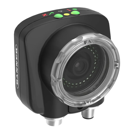
2 Overview of the Sensor The iVu Plus BCR sensor reads a wide variety of barcodes. The package consists of lighting, sensor, lens, and display. Appropriate cables and mounting brackets can be ordered for each application. Additionally, other lenses, brackets, filters and external lights are available. - Page 8 Plus BCR User's Manual LED - Green: Power; Red: Error LED - Green: Pass; Red: Fail Ethernet I/O LED Focusing Window Focusing Window Locking Clip Integrated Display www.bannerengineering.com - tel: 763-544-3164 Rev. B...
- Page 9 Plus BCR User's Manual 8-pin Euro-style (M12) female USB Cable Connector I/O Cable Connector C 12-pin Euro-style (M12) male Power and I/O Cable Connector Mounting Bracket Mounting Holes (uses supplied three M4 x 4 mm screws) iVu with Remote Display The iVu sensor for use with a Remote Display comes fully assembled with the lens and an integrated ring light if so ordered.
-
Page 10: Cable Connections
Mounting Bracket Mounting Holes (uses supplied three M4 x 4 mm screws) 2.1.2 Cable Connections iVu Plus BCR with Integrated Display The cable connections on the iVu Plus with integrated display are shown below, and power I/O connections (C) are defined in the Power I/O Connections table below. - Page 11 Plus BCR User's Manual iVu Plus BCR with Remote Display The cable connections on the iVu Plus with remote display are shown below, and power I/O connections (B) are defined in the Power I/O Connections table below. Remote Display Connector...
- Page 12 Plus BCR User's Manual Power I/O Connections Pin # Wire Color Description Direction Brown 10-30V dc Input Blue Common (Signal Ground) Input Pink External Trigger Input Gray Remote Teach Input White Output 1 Output Ready Output Yellow Strobe Out (5V dc only)
- Page 13 The sensor triggers from high to low, and Remote Teach behaves electrically like trigger. NOTE: If the device used to trigger or remote teach the iVu Plus BCR is a sinking device (that is, NPN), then there are two options regarding the use of a pull-up resistor: Option 1: Put a pull-up resistor, rated approximately 1k ohm, between the sensor's positive (+) voltage and the sensor's input as shown below.
-
Page 14: Installing And Connecting The Sensor
& Expose Based) 2.1.3 Installing and Connecting the Sensor The iVu Plus BCR sensor requires a bracket for mounting. Three brackets are available from Banner. The brackets allow the sensor to be mounted either perpendicular to the part or at an adjustable angle. - Page 15 Plus BCR User's Manual Installing Filters on the iVu Series Sensor NOTE: Failure to follow these instructions can cause damage to your iVu Series sensor. To install a filter on the iVu Series sensor with Micro Lens, use the illustration as a guide and follow the steps listed below.
-
Page 16: Live Mode Overview
2.2 Live Mode Overview The iVu Plus BCR can be configured to evaluate one or more of the supported barcode types and can look for a specific number of barcodes from 1 to 10. The barcode types are selected on the integrated touch screen by accessing Main Menu > Inspection > Bar- www.bannerengineering.com - tel: 763-544-3164... -
Page 17: Read/No Read, Pass/Fail, Match/No Match
• A No Match condition occurs when the required number of barcodes are found, but the compare is not successful. 2.2.2 Trigger Modes The iVu Plus BCR has five trigger modes that determine how the sensor captures and processes images: • External - Single •... -
Page 18: Compare Data
2.2.3 Compare Data The iVu Plus BCR has a data compare feature for comparing read barcode data against reference data. Data can be manually entered by accessing the Main Menu > Inspection > Barcode > Data Compare > Set Data screen. Data of up to 3200 characters can be entered. - Page 19 Plus BCR User's Manual The iVu Plus BCR RS232 port or ethernet port can be used to output barcode data to other applications. To access the Data Export screen, go to Main Menu > System > Communications > Data Export . The user can enable or disable this feature. When enabled: •...
-
Page 20: Remote Teach
2.3 iVu Plus BCR Emulator The iVu Plus BCR Emulator is a Windows application that allows you to operate in a Windows environment exactly as you would on the iVu Series sensor itself. In general, the Emulator is an inspection debugging tool where you can: 1. -
Page 21: Main Menu Reference
3 Main Menu Reference 3.1 Main Menu The Main Menu has four sections. Select: Inspection to modify inspection settings Imager to run the Auto Exposure routine and to make adjustments to functions like exposure, gain, and strobe. System to set output signals, communication channel parameters and to man- age the device. -
Page 22: System Menu
Plus BCR User's Manual Barcode Type Inspection Barcode Barcode Count Compare Data Compare Set Data Properties Inspection Name Inspection ID Scan Time Limit Select Stored Inspections Live Mode Add New System Sensor Mode Demo Mode Startup Delete Save to USB... -
Page 23: Sensor Mode
Plus BCR User's Manual 3.2.1 Sensor Mode Main Menu > System > Sensor Mode The sensor has two operating modes: • Live Mode, which is the normal operating mode where the sensor captures live images, scans, and verifies barcodes •... - Page 24 Plus BCR User's Manual Main Menu > System > Sensor Configuration Save to USB The Save to USB screen provides for saving sensor Configuration to a USB flash drive. The saved configuration information can be used as a backup or as a way to clone configuration information for other sensors.
-
Page 25: Sensor Information
Plus BCR User's Manual 3.2.3 Sensor Information The Sensor Information screen displays the following sensor information: • Serial Number • Firmware Version • Boot Number • Up Timer • Hour Count • Model Number • Sensor Name Main Menu > System > Sensor Information Click the right-arrow next to the Sensor Name field to display a software keyboard that allows you to change the Sensor Name. -
Page 26: Lock Sensor
Plus BCR User's Manual 3.2.4 Lock Sensor This option provides for locking the sensor to prevent accidental modification of settings. When locked, the sensor only provides access to pass/fail statistics, as well as the ability to view logs and to save them to a USB device. A lock icon in the upper left corner of the sensor display indicates that the sensor is locked. - Page 27 Plus BCR User's Manual Port Settings for Ethernet I/O Main Menu > System > Communications > Ethernet I/O In the Ethernet I/O screen you can enter the IP Address, Subnet Mask, and Gateway. Port Settings for Serial I/O Main Menu > System > Communications > Serial I/O In the Serial I/O screen you can select values for Baud Rate, Stop Bits and Parity Control.
- Page 28 Plus BCR User's Manual Industrial Ethernet Main Menu > System > Communications > Industrial Ethernet The iVuPlus device can be controlled or monitored over Industrial Ethernet using Ethernet/IP, Modbus/TCP or PCCC protocols. This document will help you to set up the iVu Plus in the desired configuration and provide you with information you will need to connect to the master device (PLC, HMI, etc.).
- Page 29 Plus BCR User's Manual Delimiters Main Menu > System > Communications > Command Channel > Delimiters In the Delimiters screen, there are three delimiter options that you can set: • Field Delimiter, which determines what is used to separate data that the sensor is sending out to a remote device.
- Page 30 Plus BCR User's Manual Data To Export Main Menu > System > Communications > Data Export > Data To Export The options in the Data To Export screen are used to determine what barcode data is exported via the serial port.
-
Page 31: Discrete I/O
Plus BCR User's Manual Image Export Channel Main Menu > System > Communications > Image Export When the Image Export Channel is enabled, the sensor will transmit the acquired image on every trigger. The image is transmitted as a bitmap (BMP) file. - Page 32 Plus BCR User's Manual Input Pullup Main Menu > System > Discrete I/O > Input Pullup The NPN version of the iVu sensor triggers from high to low, and Remote Teach behaves electrically like trigger. If using the NPN version of the sensor, select Enable.
-
Page 33: Display Settings
Plus BCR User's Manual NOTE: For Latched the signal is active until the results of an inspection cause a change in the signal output. Main Menu > System > Discrete I/O > Output 1 Output2 and Output 3 Output 2 and Output 3 can be configured in a similar fashion to Output 1. -
Page 34: Reboot Sensor
Plus BCR User's Manual Fail Hold Time The Fail Hold Time determines how long a failed image is displayed on the LCD so that you can see what failed. The sensor will continue to process any triggers and the inspection will continue normally. This time delay is just for the screen. You can set this parameter from 0 to 3600 seconds using the slider at the bottom of the screen. -
Page 35: Firmware Update
The Firmware Update screen is used to load the latest sensor firmware. The Firmware Update screen lists the firmware versions it finds in the BANNER\FIRMWARE folder on the USB drive. When you receive a firmware update from Banner Engineering, be sure to put it in the BANNER\FIRMWARE folder on the USB drive. -
Page 36: Gain
Plus BCR User's Manual Main Menu > Imager > Exposure 3.3.3 Gain Gain is an electronic boost to the image signal. Increasing Gain by using the '-' and '+' keys or moving the slider to the right increases image brightness without increasing exposure time. Note that Gain brightens both the light pixels and dark pixels and may reduce the image quality. - Page 37 Plus BCR User's Manual External-Single Mode In External-Single mode, the sensor depends on an external trigger. For each trigger, the sensor captures an image and executes one scan through the configured barcode types looking for the specified number of barcodes. This trigger mode uses the Scan Time Limit parameter ( Main Menu >...
- Page 38 Plus BCR User's Manual NOTE: A No Read condition will not occur in Continuous mode as another image capture and scan automati- cally follows. External-Gated Mode External-Gated mode is similar to Continuous mode. While an external trigger input signal is active, the sensor continues to capture images and run barcode scans until a successful Read occurs or the External Trigger input signal becomes inactive.
-
Page 39: Focus
Plus BCR User's Manual Industrial Ethernet Only When Industrial Ethernet communication channel is enabled, triggers can be received from the modes mentioned above. Triggers through Industrial Ethernet will not be executed if selected Trigger Mode is 'Continuous Scan'. If it is desired to receive triggers only through Industrial Ethernet channel, select the 'Industrial Ethernet Only'. -
Page 40: Strobe
Plus BCR User's Manual 3.3.6 Strobe The Internal Strobe configures the operation of the integrated ring light. The External Strobe configures the operation of an external light. Main Menu > Imager > Strobe External The External Strobe is a 5V output that can be used for an external light. Setting options are Always ON, Always OFF, or Exposure Based. -
Page 41: Fov
Plus BCR User's Manual Internal The Internal Strobe setting configures the operation of the integrated ring light. Setting options are Always ON, Always OFF, or Exposure Based. If Exposure Based is selected, then the ring light is on during the time the sensor is capturing an image. -
Page 42: Inspection Menu
Plus BCR User's Manual Modify FOV Use this option to reduce the size of the FOV. Main Menu > Imager > FOV > Modify FOV 3.4 Inspection Menu The Inspection menu icon is located on the Main Menu. The Inspection Menu provides options to set inspection parameters on currently running inspection and manage stored inspections. - Page 43 Plus BCR User's Manual The first time the sensor is powered up, the selection checkboxes for DataMatrix and All Linear barcode types are checked. The best practice is to check only the barcode type(s) applicable for your particular application. Note that, if All Linear is unchecked, a single linear barcode type can be selected instead.
- Page 44 Plus BCR User's Manual • EAN8 • UPCE • Postnet • IMB Checksum Verify When checksum is enabled, the sensor uses a checksum to verify the integrity of the barcode being read. Relaxed Quietzone The Quietzone is a blank margin on either side of a barcode that indicates where the barcode begins and ends. If this Quietzone isn't big enough, the sensor can have trouble decoding the barcode.
- Page 45 Plus BCR User's Manual Use Omnidirectional scanning if barcode can appear inverted on part being inspected. If 'Compare' is enabled, the sensor attempts to compare that string to decoed data in both scan directions. Inspection is marked as PASS if at least one string matches. The data that successfully matched is displayed on the screen and is exported through communication channels as requested.
- Page 46 Plus BCR User's Manual Compare Use this menu to enable or disable Data Compare. If Data Compare is enabled, data can be defined in the Compare Data screen. The data can be retrieved from a previously scanned barcode, or it can be entered using the software keyboard on the touch screen, and insignificant characters can be masked within the data.
- Page 47 Plus BCR User's Manual Edit Compare Data The Edit screen displays data that was previously read or entered in the text field. The Position of the cursor within the characters dis- played ([) in the text field is indicated at the top of the screen. Additionally, the number of characters is indicated by Length. Use the left and right arrows below the software keyboard to move the cursor between the displayed characters.
-
Page 48: Properties
Plus BCR User's Manual 3.4.2 Properties Properties Menu Main Menu > Inspection > Properties The Properties menu is used to edit an Inspection Name or set the Scan Time Limit. 3.4.3 Stored Inspections Stored Inspections Menu Main Menu > Inspection > Stored Inspections Stored Inspections is used to manage stored inspections. -
Page 49: Logs Menu
Plus BCR User's Manual Add New Inspection Screen Main Menu > Inspection > Stored Inspections > Add New This screen is used to add a new inspection. The sensor can store up to 30 inspections. When you add a new one, it will begin running. -
Page 50: Inspection Logs
Plus BCR User's Manual 3.5.1 Inspection Logs This menu provides for configuring and viewing Inspection Logs. Inspection Logs are stored inspection records that include a captured image, the parameters used to inspect it, and the results of that inspection. Up to ten Inspection Logs can be held in memory on the sensor. - Page 51 Plus BCR User's Manual View Logs Inspection Logs appear as a strip of film. You can select a frame to view a specific image. Use the icon in the lower right of the screen to save the logs to the USB drive. Logs saved to the USB drive can be imported into the emulator. Click the Clear button to clear Inspection Logs.
-
Page 52: System Logs
Plus BCR User's Manual 3.5.2 System Logs The System Log contains configuration change information, other notifications, and any errors or warnings that may be encountered. • Click the icon in the upper left corner of the screen to show/hide the time column. -
Page 53: Display Modes
4 Display Modes In the upper left of the screen is an icon for accessing different Display Modes: • Display Annotations • Hide Annotations • Display Statistics. 4.1 Display/Hide Annotations Click the icon in the upper-left of the screen to display annotations. When annotations are on, the display shows the data the sensor has read. -
Page 54: Inspection Statistics
Plus BCR User's Manual 4.1.1 Inspection Statistics The History screen shows inspection statistics: • Total Frames - Total number of objects counted • Passed - running total of parts that passed inspection • Failed - running total of parts that failed inspection •... -
Page 55: Barcode Viewer
Plus BCR User's Manual 4.1.3 Barcode Viewer To view detailed information about a particular barcode, click the arrow next to the Barcode # to access the Barcode Viewer screen. If Data Compare is disabled, The Barcode Viewer screen shows a single text box indicating the index number of the barcode and the data the sensor is reading. - Page 56 Plus BCR User's Manual www.bannerengineering.com - tel: 763-544-3164 Rev. B...
-
Page 57: Setting Up For An Inspection
• Capture the barcode with lighting that optimizes its contrast and separates it from the background. Depending on the target, this may mean the integral ring light is not the best choice and other Banner lights should be considered. • Adjust the mounting angle to provide the clearest image of the barcode. The mounting bracket lets you easily position and adjust the sensor on your line. - Page 58 Plus BCR User's Manual • Main Menu > Imager > Exposure www.bannerengineering.com - tel: 763-544-3164 Rev. B...
- Page 59 Plus BCR User's Manual 4. Go to Main Menu > Imager > Focus to adjust the focus while monitoring the Focus Number: For Micro-lens Models Only: 1. Use the supplied 1/16" hex key to loosen the Focusing Window locking screw (D), then adjust focus on the iVu Series sensor using the clear Focusing Window (B).
- Page 60 Plus BCR User's Manual Micro-Lens Models Locking Screw Filter Cap (optional) Filter (optional) NOTE: Filter Kits are available separately. www.bannerengineering.com - tel: 763-544-3164 Rev. B...
-
Page 61: Setting Up A Barcode Application
5.2 Setting Up a Barcode Application This section describes how to set up the iVu Plus BCR sensor. 1. Go to Main Menu > Inspection > Barcode > Barcode Type to select one or more Barcode Types from the list. -
Page 62: Setting Up For Data Compare
5.3 Setting up for Data Compare This section describes how to set up the iVu Plus BCR sensor to compare decoded barcode data against some reference. For this exam- ple, the reference data will be from a previously decoded barcode. - Page 63 Plus BCR User's Manual 3. Press the Yes button. 4. Press the Home icon to return to the main screen. For all subsequent triggers, when the sensor reads the barcode data, it will compare it against this reference data.
- Page 64 Plus BCR User's Manual www.bannerengineering.com - tel: 763-544-3164 Rev. B...
-
Page 65: Ivu Plus Communications
(PLC, HMI, etc.). 6.1.2 Communication Channels The iVu Plus BCR supports up to four communications channels . To access the channels, go to Main Menu > System > Communica- tions . • Command Channel — a bi-directional communication protocol that currently supports ASCII and enables other devices to remotely control the iVu Plus sensor and access sensor results •... - Page 66 6.1.4 Command Channel Sample Application The iVu Plus BCR installation CD has a Command Channel sample application that provides an easy interface to execute commands. In a production environment, you will need to create your own application for bi-directional communication with the sensor.
-
Page 67: Data Export
6.1.5 Sample Application The iVu Plus BCR installation CD has a Data Export sample application that provides for viewing exported data while setting up the sensor, etc. In a production environment, you will need to create your own application to process data exported from the sensor. -
Page 68: Image Export
6.1.6 Image Export Sample Application The iVu Plus BCR installation CD has a Image Export sample application that provides a way to save exported images. In a production environment, you will need to write your own application to process exported images, for example to display them on an HMI or to save them to disk. -
Page 69: Enabling Communications
Plus BCR User's Manual 6.2 Enabling Communications 6.2.1 Setting Up Ethernet Communications The following is the general flow for setting up for Ethernet communications between the iVu Plus sensor and a remote device: On the Windows PC, configure the IP address as follows:... - Page 70 Plus BCR User's Manual Windows XP Windows 7 4. In the Internet Protocol (TCP/IP) Properties dialog, select Use the following IP address and make sure that the IP address is 192.168.0.2, and the subnet mask is 255.255.255.0. 4. In the Internet Protocol (TCP/IPv4) Properties dialog, se- lect Use the following IP address and make sure that the IP address is 192.168.0.2, and the subnet mask is...
- Page 71 Plus BCR User's Manual 2. To enable the command channel over Ethernet: a. Go to Main Menu > System > Communications > Command Channel > Connection , and select Ethernet [IP Port # 32000]. b. Configure the field and end-of-frame delimiters. Go to Main Menu > System > Communications > Command Channel >...
- Page 72 Plus BCR User's Manual Valid end-of-frame delimiters are: <comma>, <colon>, <semicolon>, <CR>, <CR><LF>, <LF><CR>, or <ETX>. c. Verify that the iVu receives and transmits data correctly. 3. To enable Data Export over Ethernet: a. Go to Main Menu > System > Communications > Data Export > Connection and select Serial I/O from the drop-down.
- Page 73 Plus BCR User's Manual c. Go to Main Menu > System > Communications > Data Export > Output Format and select the Start String, Delimiter, and End String. d. Go to Main Menu > System > Communications > Data Export > Advanced .
-
Page 74: Setting Up Serial Communications
Plus BCR User's Manual During the Data and Image export operation the sensor's output channels might become full. This can occur if the sensor is producing export data (frames) faster than the data can be exported from the device (due to bandwidth limitations) or faster than the client is reading the channel export data. - Page 75 Plus BCR User's Manual 3. To enable the command channel over the serial connection: a. Go to Main Menu > System > Communications > Command Channel > Connection and select Serial I/O. b. Configure the field and end-of-frame delimiters. Go to Main Menu > System > Communications > Command Channel >...
- Page 76 Plus BCR User's Manual d. Verify that the iVu receives and transmits data correctly. 4. To enable Data Export over the serial connection: a. Go to Main Menu > System > Communications > Data Export > Connection and select Serial I/O from the drop-down.
- Page 77 Plus BCR User's Manual c. Go to Main Menu > System > Communications > Data Export > Output Format and select the Start String, Delimiter, and End String. d. Go to Main Menu > System > Communications > Data Export > Advanced .
- Page 78 Plus BCR User's Manual During the Data and Image export operation the sensor's output channels might become full. This can occur if the sensor is producing export data (frames) faster than the data can be exported from the device (due to bandwidth limitations) or faster than the client is reading the channel export data.
-
Page 79: Testing And Troubleshooting Ivu Plus Communications
7 Testing and Troubleshooting iVu Plus Communications 7.1 Understanding the Communication Log The iVu Plus sensor includes the following Communication Logs: • Command Channel Log that can be used to ensure that commands are properly formed (syntax is correct), and provides a history of commands issued along with responses to these commands. -
Page 80: Ethernet I/O
Plus BCR User's Manual Icon Description If the command takes a long time to process, the last long entry will change to an hourglass (for example, during trigger of long inspections). For Ethernet channels: • The channel's log will show an Enabled entry that indicates which port is being listened to. -
Page 81: Using The Ivu Command Channel Sample Application Or A Terminal Program For Testing
Plus BCR User's Manual Port Errors The Port Errors screen can help to debug communications channel issues: Parity, Break, and Framing indicate mismatched port settings or, in the case of Break, incorrect cabling. 7.3.2 Using the iVu Command Channel Sample Application or a Terminal Program for Test-... - Page 82 Plus BCR User's Manual 2. On the requesting device, transmit one or more bytes to the iVu sensor. • If the data byte values appear correct and the number sent by the requesting device matches the number received by the iVu sensor, then the transmit/receive functionality is working properly.
- Page 83 Plus BCR User's Manual 3. If the byte count does not match, re-verify that the settings on both devices match exactly. If no bytes are received, re-check the wiring. If the correct response frame is received, then basic electrical and port settings are correct.
-
Page 84: Command Channel Primer
Plus BCR User's Manual 8 Command Channel Primer 8.1 Command Channel Commands All iVu command channel request command frames use the following syntax: >> command group item value<EOF> Notes <EOF> is the end-of-frame delimiter. See below for a description. -
Page 85: String Delimiters And Escaping
Plus BCR User's Manual For example, the following is a series of command requests and responses. The first request sets the trigger mode to command and, once the sensor responds with an "OK," the next command request is issued to do (or execute) the trigger. -
Page 86: Conventions Used For Examples
Plus BCR User's Manual Command Channel Command Status The command status is either OK or ERROR. If OK, then the command has fully and successfully completed. If an error is returned it is in the form ERROR nnnnn_ERROR_IDENTIFIER (for example ERROR 10001_COMMAND_NOT_RECOGNIZED). Refer to... -
Page 87: Ivu Plus Command Channel Reference
Plus BCR User's Manual 2. Set the compare data. >> set bcr_input comparedata "0043000011201"\x0D\x0A << OK\x0D\x0A 3. Trigger the sensor. >> do trigger\x0D\x0A << OK\x0D\x0A 4. Check that the inspection passed. >> get inspection status\x0D\x0A << OK\x0D\x0A << Pass\x0D\x0A 5. - Page 88 Plus BCR User's Manual Command Group Item Description Info RemoteModelNumber The model number of the re- mote display as a string. Info RemoteSerialNumber The serial number of the remote display as a string. Examples >> get info companyname\x0D\x0A <<...
- Page 89 Plus BCR User's Manual Command Group Item Description Ethernet Gateway Set new Gateway IP address. A 'Re- boot' command is required to be sent from the command channel to make the new address effective. Examples >> do system save\x0D\x0A <<...
- Page 90 Plus BCR User's Manual Command Group Item Description eration is required to persist this value. Trigger Mode The sensor's triggering mode. This value must match the modes supported by the sensor. This value can be modified us- ing the sensor's touchscreen.
- Page 91 Plus BCR User's Manual Command Group Item Description pixels This value can be modi- fied using the sensor's touchscreen. This remotely modified value is not persisted to the sensors permanent mem- ory. The 'Save' operation is re- quired to persist this value.
- Page 92 Plus BCR User's Manual 8.4 Teach Command Group Command Group Item Description Teach NextTrigger This commands forces the sen- sor to perform the Remote Teach operation on the next trigger. This command can be performed using the sensor's touchscreen.
- Page 93 Plus BCR User's Manual Command Group Item Description cleared (reset) whenever history is cleared. This value is cleared (reset) when the device starts up or is rebooted. History MissedTriggers This value indicates the number of missed triggers for the active inspection.
- Page 94 Plus BCR User's Manual Command Group Item Description er history is cleared. This value is cleared (reset) when the de- vice starts up or is rebooted. History MaxBarcodeCount This value indicates the maxi- mum number of barcodes read for the active inspection This value is cleared (reset) whenev- er history is cleared.
- Page 95 Plus BCR User's Manual << Fail\x0D\x0A >> get inspection executiontime\x0D\x0A << OK\x0D\x0A << 37.739\x0D\x0A 8.4 BCR_INPUT Command Group Command Group Item Description BCR_INPUT CompareData The Barcode inspection com- pare data string. This string must start and end with the dou- ble quote character.
- Page 96 Plus BCR User's Manual Command Group Item Description can be modified using the sen- sor's touchscreen. This remote- ly modified value is not persis- ted to the sensors permanent memory. The 'Save' operation is required to persist this value.
-
Page 97: Command Channel Error Codes
Plus BCR User's Manual Command Group Item Description is cleared (reset) when the de- vice starts up or is rebooted. Examples 8.5 Command Channel Error Codes Numeric ID Text ID Description 00000 SUCCESS Command processed successfully 10000 EMPTY_FRAME_RECEIVED Indicates that the request was empty. The... - Page 98 Plus BCR User's Manual Numeric ID Text ID Description 10920 SENSOR_TYPE_NOT_ACTIVE Command specified belongs to a different sensor type. 15000 VALUE_INVALID Text value is invalid / unknown 15050 VALUE_INVALID Text value is invalid - expecting True or False 15100...
-
Page 99: Industrial Ethernet Overview
9 Industrial Ethernet Overview 9.1 Device Setup 9.1.1 Set IP Address When shipped, the device is assigned a default IP address - 192.168.0.1, a default Subnet Mask - 255.255.255.0, and a default gateway - 0.0.0.0. To change these defaults, click on Main Menu > System > Communications > Ethernet I/O. 9.1.2 Set Industrial Ethernet Protocol (EIP/Modbus/TCP/PCCC) The Industrial Ethernet communication channel is disabled by default. -
Page 100: Supported Functions
Plus BCR User's Manual 9.2 Supported Functions The iVu Plus Series sensor is controlled over Ethernet/IP and Modbus/TCP using the input and output data it makes available as a slave device for those protocols. Here are some of the Sensor operations that can be performed using input and output values: •... - Page 101 Plus BCR User's Manual Input Commands The following commands need to be executed using Command ID and the Command Bit stated above. Command Command ID Description Data Type Trigger Trigger Mode 10001 The sensor's triggering mode. This value must match the...
-
Page 102: Ivu Output Values
Plus BCR User's Manual Command Command ID Description Data Type BCR inputs Compare String 11001 The Barcode inspection compare data string. This string must Byte Array start and end with the double quote character Compare Mask 11002 The Barcode inspection compare string mask in binary format;... -
Page 103: Ethernet/Ip
To create an implicit Class 1 configuration to the iVu Plus using EIP when using a ControlLogix family PLC, configure the iVu Plus as a “Generic Ethernet Module” under the ENET_MODULE. The following is a sample setup of Banner sensor: 1. - Page 104 Plus BCR User's Manual www.bannerengineering.com - tel: 763-544-3164 Rev. B...
- Page 105 Plus BCR User's Manual 2. Select Module. • • Rev. B www.bannerengineering.com - tel: 763-544-3164...
- Page 106 Plus BCR User's Manual 3. Configure Module Properties. Assembly Objects on page 112 for more information on each specific assembly instance. Input Assembly (100) Input Assembly (101) www.bannerengineering.com - tel: 763-544-3164 Rev. B...
- Page 107 Plus BCR User's Manual Input Assembly (102) Select or deselect Unicast Connection as desired. NOTE: The data type in the Comm Format must be changed to an INT. NOTE: The minimum allowed RPI is 50 ms. Rev. B www.bannerengineering.com - tel: 763-544-3164...
- Page 108 Plus BCR User's Manual 4. If the module configuration was successful, the following information should be displayed: If the module configuration was not successful, the RSLogix 5000 software will indicate errors similar to the ones displayed below: ERROR: Assembly Instance number and/or size incorrect.
- Page 109 Plus BCR User's Manual 5. Locate the memory map setup from Banner module to PLC memory map. C = Configuration (not used) I = Inputs to PLC (outputs from iVu Plus) O = Outputs from PLC (inputs to iVu Plus) Rev.
- Page 110 Plus BCR User's Manual The iVu Plus memory map expanded. I = Inputs to PLC (outputs from iVu Plus). www.bannerengineering.com - tel: 763-544-3164 Rev. B...
- Page 111 Plus BCR User's Manual Sample map demonstrating string values: Memory Map: Default NOTE: ControlLogix string format. "iVu Plus Image Sensor" Memory Map: "Style" changed to ASCII All data is initially transferred as "INT" data type. An ASCII string looks like gibberish in this format. Changing the "style" to ASCII instead of "Decimal"...
-
Page 112: Assembly Objects
Plus BCR User's Manual 9.4.2 Assembly Objects Outputs from PLC iVu_OUTPUT1 Instance 0x70 (112) - 6 Registers WORD # WORD NAME DATA TYPE Input Bits Register 16-bit integer Product Change Number 32-bit integer reserved iVu_OUTPUT2 0x71 (113) - 240 Registers... - Page 113 Plus BCR User's Manual Inputs to the PLC iVu_Input1 0x64 (100) - 30 Registers WORD # WORD NAME DATA TYPE Input Bits ACK Register 16-bit integer Output Bits Register 16-bit integer Error Code 32-bit integer Inspection Number 32-bit integer...
- Page 114 Plus BCR User's Manual Sensor Type - Blemish (iVu Plus TG) WORD # WORD NAME DATA TYPE WORD # WORD NAME DATA TYPE Input Bits ACK Register 16-bit integer Sensor Type ID 16-bit integer Output Bits Register 16-bit integer...
- Page 115 Plus BCR User's Manual Sensor Type - Sort (iVu Plus TG) WORD # WORD NAME DATA TYPE WORD # WORD NAME DATA TYPE Input Bits ACK Register 16-bit integer Sort Pattern 5 Count 16-bit integer Output Bits Register 16-bit integer...
- Page 116 Plus BCR User's Manual Sensor Type - Barcode (iVu Plus BCR) WORD # WORD NAME DATA TYPE WORD # WORD NAME DATA TYPE Input Bits ACK Register 16-bit integer Barcode-1 Type 16-bit integer Output Bits Register 16-bit integer Barcode-1 Actual Decoded...
- Page 117 Plus BCR User's Manual iVu_Input 3 0x66 (102) Sensor Type (iVu Plus BCR) WORD # WORD NAME DATA TYPE WORD # WORD NAME DATA TYPE Input Bits ACK Register 16-bit integer Barcode-5 Type 16-bit integer Output Bits Register 16-bit integer...
- Page 118 Plus BCR User's Manual Flags Output Bit Flags Bit Position Gated Teach Product Command Set BCR Set BCR Trigger Trigger Latch Change Mask ACK String ACK Input ACK Bits Bit Position Set BCR Set BCR Gated Teach Product Command...
-
Page 119: Configuration Assembly Object
Plus BCR User's Manual 9.4.3 Configuration Assembly Object The iVuPlus EIP implementation does not support an assembly object configuration instance. However, one is required for creation of implicit Class 1 connections on a ControlLogix family PLC. Therefore, a configuration instance is defined as instance number 0x80 (128 decimal). -
Page 120: Sample Timing Diagram
Plus BCR User's Manual 9.4.6 Sample Timing Diagram X, Y, Z: Represent snapshot in time Product Change X+Y+Z Product Change Ready Product Change ProductChange ProductChange ProductChange Verify : Verify : ACK = ‘1 ’ Ready = 1 Ready = 1... - Page 121 Plus BCR User's Manual Teach Latch X + Y X + Y + Z Teach Latch Ready Teach Latch ACK TeachLatch TeachLatch TeachLatch ACK Verify : Verify : = ‘1 ’ Ready = 1 Ready = 1 Teach will...
- Page 122 Plus BCR User's Manual Trigger X + Y X + Y + Z Trigger Ready TriggerACK Trigger = 1 Trigger = 0 Verify : Verify : TriggerACK = ‘1 ’ Ready = 1 Ready = 1 Read Results TriggerACK TriggerACK www.bannerengineering.com - tel: 763-544-3164...
- Page 123 Plus BCR User's Manual Gated Trigger X + Y X + Y + Z M Gated Trigger Ready Gated Trigger ACK GatedTrigger GatedTrigger GatedTrigger GatedTrigger = 0 (Abort ) Inspection could not be completed GatedTriggerACK Verify : Verify : = ‘1 ’...
-
Page 124: Modbus/Tcp
Plus BCR User's Manual 9.5 Modbus/TCP The Modbus/TCP protocol provides device control using register and coil banks defined by the slave device. This section defines the iVu Plus Modbus/TCP register and coil banks. From the point of view of the slave device (PLC), there is one output coil registers and two Input Coil registers. -
Page 125: Holding Registers
Plus BCR User's Manual 9.5.1 Holding Registers The Holding registers are used by the PLC to push values to the iVu Plus sensor. These values are accessed in the register address range of 40001 - 40240. To write, use Function Codes 6/16 (Preset Single/Multiple Registers). Also available in this range of registers are the registers containing output data. -
Page 126: Output Registers
Plus BCR User's Manual 9.5.2 Output Registers The Output registers are used to send output values from the iVu Plus to the PLC. Note that some devices (such as Modicon family PLCs) cannot access data using the 30000 range of register addresses. For these devices, the output values are also available using the 40000 range of addresses (at offset 41000). - Page 127 Plus BCR User's Manual Sensor Type - Blemish (iVu Plus TG) REGISTER WORD NAME DATA TYPE REGISTER WORD NAME DATA TYPE 30001 Coil ACK Bits 16-bit integer 30056 Sensor Type ID 16-bit integer 30002 Status Coil Bits 16-bit integer...
- Page 128 Plus BCR User's Manual Sensor Type - Match (iVu Plus TG) REGISTER WORD NAME DATA TYPE REGISTER WORD NAME DATA TYPE 30001 Coil ACK Bits 16-bit integer 30056 Sensor Type ID 16-bit integer 30002 Status Coil Bits 16-bit integer...
- Page 129 Plus BCR User's Manual Sensor Type - Sort (iVu Plus TG) REGISTER WORD NAME DATA TYPE REGISTER WORD NAME DATA TYPE 30001 Coil ACK Bits 16-bit integer 30061 Sort Pattern 3 Count 16-bit integer 30002 Status Coil Bits 16-bit integer...
- Page 130 Plus BCR User's Manual Sensor Type - Barcode-1 (iVu Plus BCR) REGIS- WORD NAME DATA TYPE REGIS- WORD NAME DATA TYPE 30001 Coil ACK Bits 16-bit integer 30262 Barcode-2 Type 16-bit integer 30002 Status Coil Bits 16-bit integer 30263...
-
Page 131: Input And Output Coils
Plus BCR User's Manual 9.5.3 Input and Output Coils The Modbus TG / BCR Output Coils are used to push single bit commands from the PLC/HMI to the iVu Plus sensor. To access the Modbus/TCP Output and Input Coils use Function Code 02 (Read Input Status). -
Page 132: Plc5 And Slc 5 (Pccc)
Plus BCR User's Manual 9.6 PLC5 and SLC 5 (PCCC) Allen-Bradley’s PLC5 and SLC 500 family of devices use PCCC communications over Ethernet/IP. iVu Plus supports these PLCs using input and output register arrays. The Output Flags, ACK Flags and Input Flags bit definitions are the same as defined in the EIP Assem- bly Objects section. - Page 133 Plus BCR User's Manual 2. Read. IP Address of the iVu Plus is entered here. 3. Write. Message command_writing to N14 table on iVu Plus Rev. B www.bannerengineering.com - tel: 763-544-3164...
-
Page 134: Output Registers
Plus BCR User's Manual 4. Write. IP Address of the iVu Plus is entered here. 9.6.2 Output Registers The Input registers are used by the PLC to push values to the iVu Plus sensor. MSG (message) commands used to Read (N7) and Write (N14) to the sensor. -
Page 135: Input Registers
Plus BCR User's Manual 9.6.3 Input Registers The Output registers are used to push output values from the iVu Plus to the PLC. MSG (message) commands used to Read (N7) and Write (N14) to the sensor. Input Registers Map (N7) - Page 136 Plus BCR User's Manual Sensor Type - Blemish (iVu Plus TG) WORD # WORD NAME DATA TYPE WORD # WORD NAME DATA TYPE Coil ACK Bits 16-bit integer Sensor Type ID 16-bit integer Output Coil Bits 16-bit integer 56-57...
- Page 137 Plus BCR User's Manual Sensor Type - Sort (iVu Plus TG) WORD # WORD NAME DATA TYPE WORD # WORD NAME DATA TYPE Coil ACK Bits 16-bit integer Sort Pattern 3 Count 16-bit integer Output Coil Bits 16-bit integer...
- Page 138 Plus BCR User's Manual Sensor Type - Barcode-1 (iVu Plus BCR) WORD # WORD NAME DATA TYPE WORD # WORD NAME DATA TYPE Coil ACK Bits 16-bit integer Barcode-2 Type 16-bit integer Output Coil Bits 16-bit integer Barcode-2 Length...
-
Page 139: Input And Output Flags
Plus BCR User's Manual 9.6.4 Input and Output Flags The Input Flags are used to command execution of basic functions. The Output Coils are used to push single bit outputs from the iVu Sensor to the PLC. The 32 bits of Output Coils can also be accessed using the bits of the first two Output Registers ( ACK Flags and Output Flags). -
Page 140: Error Codes
Plus BCR User's Manual 9.7 Error Codes The iVuPlus sensor provides error codes in cases when commands failed to execute successfully. If such an error occurs, the Execution Error flag is set in the Output Bit/Coil Register. When this bit is set, read the Error Code register to know the reason of failure. Below is... -
Page 141: Ethernet Diagnostics
Plus BCR User's Manual iVuPlus sensor provides several tools to help diagnose communication issues when using Industrial Ethernet channel. 9.8.1 Ethernet Diagnostics To verify Ethernet connectivity, please follow these steps: • Verify that all the cables are connected and properly seated. -
Page 142: Networking And Tcp/Ip Diagnostics
Plus BCR User's Manual • If the Link Status indicates that there is no link, please inspect the wiring, and verify that your Ethernet switch is powered up. • If the link parameters are not as expected (wrong baud rate or duplex) try the following: •... - Page 143 Plus BCR User's Manual • Type in a ping command, specifying the sensor IP address as an argument. You should see a series of responses from the camera: • You should also see the Packets Received and Packets Sent count on the Ethernet I/O Status page in the camera increment by at least 4.
-
Page 144: Industrial Protocols Troubleshooting
Plus BCR User's Manual 9.8.3 Industrial Protocols Troubleshooting MODBUS Protocol MODBUS protocol relies on the fundamental TCP/IP connectivity to establish connections and transport data. Once you have verified Networking and TCP/IP connectivity, you should have little or no problems establishing a MODBUS connection. - Page 145 Plus BCR User's Manual Ethernet/IP and PCCC Protocols Ethernet/IP and PCCC protocols rely on CIP protocol to establish communications and exchange data. CIP protocol, in turn, utilizes TCP/ In addition, Ethernet/IP implements I/O messaging. I/O messaging allows two devices, iVu sensor and the PLC, to continuously syn- chronize data sets between each other.
- Page 146 Plus BCR User's Manual Once the CIP and I/O connections are established, the Industrial Protocols Status page will show the details of the connection: Most of the errors in establishing the CIP and I/O connections have to do with specifying the proper Input and Output assembly IDs and sizes.
-
Page 147: Debugging Inspections
4. Copy the Sensor Configuration from the USB Thumb Drive to the folder where the Emulator is installed on the PC. For example, if the sensor name is myName and the iVu Emulator is installed in the default location on the PC, copy the file <USB>:\BANNER \myName\CONFIG.CFG to C:\Program Files\Banner Engineering\iVu Series. -
Page 148: How To Debug Using The Emulator From The Usb Flash Drive
When prompted, select Yes to save sensor configuration along with the Inspection Logs. The location of these files on the USB Thumb Drive will be displayed after the operation is completed—the Inspection Logs are saved in <USB>:\BANNER \<SENSOR_NAME>\InspLog and the sensor configuration is saved in <USB>:\BANNER\<SENSOR_NAME>. For example, if the sensor name is myName: •... -
Page 149: Ivu Series: Updating The Sensor
Banner Engineering may release new versions of the sensor firmware in the future. New firmware releases can be downloaded from Banner's website or can be obtained by ordering the latest Product CD. The following steps will guide you through the process of updat- ing the iVu firmware. -
Page 150: How To Reset The Sensor Password
9. Close the Emulator program and the Sensor Name will be saved to the CONFIG.CFG file. 10. If running the Emulator on the PC, copy the CONFIG.CFG file back to the original folder on the USB drive—<USB>:\BANNER \<SENSOR_NAME> (for example <USB>:\BANNER\myName). -
Page 151: How To Use Bitmap Image Files With The Ivu Emulator
The iVu Emulator will be running using the .bmp files from Step 1. NOTE: Banner does not recommend setting up inspections using these 8-bit grayscale images because you will always end up modifying the configuration after loading it on the sensor on the line. A better choice would be to set up the inspection on the emulator using Inspection Logs from the sensor. -
Page 152: Led Indicator Troubleshooting
Clear System Error button at the bottom of the screen (a sensor reboot is not required). 3. If the error occurs again, you can try rebooting the sensor to see if that fix- es the problem. If the problem persists, contact Banner customer support. 12.2 Warnings www.bannerengineering.com - tel: 763-544-3164... - Page 153 Plus BCR User's Manual Warnings are atypical conditions that the sensor detects and fixes. Warning are highlighted in yellow in the System Log, and can typically be ignored. Rev. B www.bannerengineering.com - tel: 763-544-3164...
- Page 154 Warranty: Banner Engineering Corporation warrants its products to be free from defects gain 36 for a period of one year. Banner Engineering Corporation will repair or replace, free of charge, any product of its manufacture found to be defective at the time it is returned to the factory during the warranty period.
- Page 155 loading from 24 saving to 24 Touchscreen Calibration 34 Rev. B www.bannerengineering.com - tel: 763-544-3164...
Need help?
Do you have a question about the iVu Plus BCR and is the answer not in the manual?
Questions and answers