Bowflex BXT6 Service Manual
Hide thumbs
Also See for BXT6:
- Troubleshooting (3 pages) ,
- Troubleshooting manual (4 pages) ,
- Installation manual
Table of Contents
Advertisement
™
™
Table of Contents
Section Code
Section
1
1
1
1
1
1
1
1
1
1
1
1
1
1
1
1
1
1
1
1
1
1
Mechanical / Modification Procedures
2
Part Replacement
3
4
5
6
7
8
Nautilus, Inc., www.NautilusInc.com, 5415 Centerpoint Parkway, Groveport, OH 43125 U.S.A. - Customer Service: North America (800) 605-3369, csnls@nautilus.com | outside U.S. www.nautilusinternational.com
| Printed in China | © 2018 Nautilus, Inc. | Bowflex and the B logo are trademarks owned or licensed by Nautilus, Inc., registered or otherwise protected by common law in the United States and other nations. |
ORIGINAL DOCUMENT - ENGLISH VERSION ONLY
8020418.121518.A
Bowflex
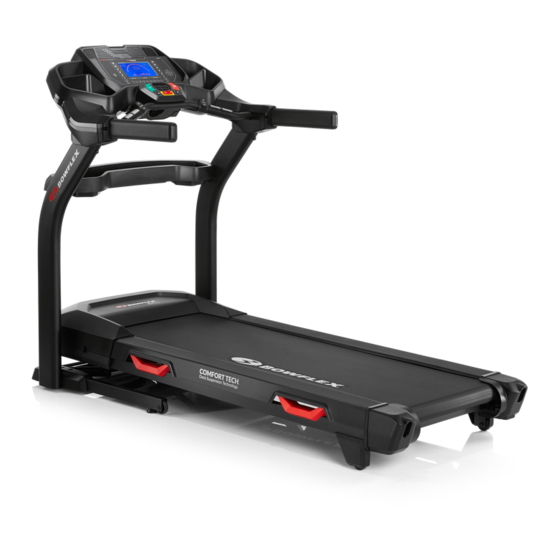
BXT6 / BXT028 / BXT088 Treadmill
®
Service Manual
Page Number
2
3
4
5
5
6
8
10
10
11
12
12
13
13
14
15
16
18
30
31
32
33
34
36
42
47
52
56
60
1
Service Manual
8020417.121518.A
Advertisement
Table of Contents

Subscribe to Our Youtube Channel
Related Manuals for Bowflex BXT6


Summary of Contents for Bowflex BXT6
-
Page 1: Table Of Contents
Nautilus, Inc., www.NautilusInc.com, 5415 Centerpoint Parkway, Groveport, OH 43125 U.S.A. - Customer Service: North America (800) 605-3369, csnls@nautilus.com | outside U.S. www.nautilusinternational.com | Printed in China | © 2018 Nautilus, Inc. | Bowflex and the B logo are trademarks owned or licensed by Nautilus, Inc., registered or otherwise protected by common law in the United States and other nations. | ORIGINAL DOCUMENT - ENGLISH VERSION ONLY 8020418.121518.A... -
Page 2: Important Safety Instructions
Nautilus, Inc., www.NautilusInc.com, 5415 Centerpoint Parkway, Groveport, OH 43125 U.S.A. - Customer Service: North America (800) 605-3369, csnls@nautilus.com | outside U.S. www.nautilusinternational.com | Printed in China | © 2018 Nautilus, Inc. | Bowflex, the B logo, and Bowflex Toolbox are trademarks owned or licensed by Nautilus, Inc., registered or otherwise protected by common law in the United States and other nations. Google Play™, and MyFitnessPal... -
Page 3: Safety Warning Labels And Serial Number
SAFETY WARNING LABELS AND SERIAL NUMBER REVISIONS REVISION REV DESCRIPTION APPROVED DATE DRAWING RELEASE 12247 DLOVELY CAUTION 12745 8/17/09 CHANGED SIZE DLOVELY Risk of Injury to Persons - To Avoid injury, use extreme caution when stepping onto or off of a moving belt. Read instruction REVISIONS REVISION REV DESCRIPTION APPROVED DATE manual before using. -
Page 4: Specifications
SPECIFICATIONS Power Requirements: 120V 220V Operational Voltage: 120V AC, 60Hz 220V - 240V AC, 50/60Hz Operating Current: 15 A Heart Rate Chest Strap: 1 CR2032 battery 1 CR2032 battery 140 cm (55.1”) 136 kgs (300 lbs) Maximum User Weight: 17990 cm Total Surface Area (footprint) of equipment: 43.7 cm (17.2 inches) Maximum Inclined Deck Height:... -
Page 5: Grounding Instructions
(for a 120V AC system ) Grounding Instructions This product must be grounded. If it should malfunction or break down, grounding provides a path of least resistance for electric current to reduce the risk of electric shock. This product is equipped with a cord having an equipment-grounding conductor and a grounding plug. The plug must be plugged into an appropriate outlet that is properly installed and grounded in accordance with all local codes and ordinances. -
Page 6: Emergency Stop Procedure
Emergency Stop Procedure The Treadmill machine is equipped with a Safety Key that can prevent serious injury, as well as prevent children from playing with and/or being injured on the machine. If the Safety Key is not correctly inserted into the Safety Key Port, the belt will not operate. Always attach the Safety Key Clip to your clothing during your workout. -
Page 7: Moving And Storing The Machine
Moving and Storing the Machine The machine can be moved by one or more persons. Use caution when you move the machine. The treadmill is heavy and can be awkward. Make sure that your own physical strength is capable of moving the machine. Use a second person if necessary. 1. Before the machine can be moved, inspect the Walking Deck to be sure the Incline setting is at “1”. If necessary, adjust the Incline setting to “1”. -
Page 8: Unfolding The Machine
7. Make sure that the locking mechanism is engaged. Carefully pull back on the walking deck and make sure that it does not move. When you do this, keep clear of movement path in case the treadmill lock is not engaged. Do not lean against the treadmill when it is folded. - Page 9 4. The hydraulic lift is set up to drop lightly. Hold onto the walking deck until approximately 2/3 of the movement down. Make sure that you use proper lifting technique; bend your knees and keep your back straight. Lower the weight with your legs. The walking deck can possibly drop quickly in the last part of the movement.
-
Page 10: Leveling The Machine
Leveling the Machine The machine needs to be leveled if your workout area is uneven. To adjust: 1. Place the machine in your workout area. 2. Adjust the levelers until they all contact the floor. Do not adjust the levelers to such a height that they detach or unscrew from the machine. Injury to you or damage to the machine can occur. -
Page 11: Connectivity
CONNECTIVITY Bluetooth Connectivity with the “Bowflex Results Series™” Fitness App ® This fitness machine is equipped with Bluetooth connectivity and can wirelessly sync with the “Bowflex Results Series™” Fitness App on supported ® devices. The Software App syncs with your fitness machine to track total calories burned, time, distance, and more. Records and stores every work- out for quick reference. Plus, it automatically syncs your workout data to MyFitnessPal and Under Armour Connected Fitness to make hitting your ® ® daily calorie goal easier than ever! Track your results and share with friends and family. -
Page 12: Maintenance
MAINTENANCE Read all maintenance instructions fully before you start any repair work. In some conditions, an assistant is required to do the necessary tasks. Equipment must be regularly examined for damage and repairs. The owner is responsible to make sure that regular maintenance is done. -
Page 13: Adjusting The Belt Tension
Adjusting the Belt Tension If the walking belt starts to slip during use, it is necessary to adjust the tension. Your treadmill has tension bolts at the rear of the treadmill. Remove the Safety Key and place it in a secure location. When this machine is not in operation, remove the Safety Key and keep out of the reach of children. -
Page 14: Lubricating The Walking Belt
Lubricating the Walking Belt Your treadmill is equipped with a low maintenance deck and belt system. The Walking Belt is pre-lubricated. Belt friction can affect the function and life of the machine. Lubricate the belt every 3 months or every 25 hours of use, whichever comes first. Even if the treadmill is not in use, silicone will dissipate and the belt will dry out. For the best results, lubricate the deck periodically with a silicone lubricant using the following instructions: Turn off the power to the machine with the power switch. -
Page 15: Heart Rate Chest Strap Battery Replacement
Replace Batteries in Chest Strap The heart rate (HR) chest strap uses a CR2032 battery. Do not perform this procedure outdoors or in moist or wet locations. Using a coin, loosen the slotted cover on the battery bay. Remove the CR2032 cover and battery. -
Page 16: Maintenance Parts
Maintenance Parts Left Upper Junction Cover Console Assembly Heart Rate Chest Strap Left Junction Cover End Cap Right Upper Junction Cover Side Handlebar, Left Left Lower Junction Cover Left Junction Cover End Cap Right Lower Junction Cover Safety Key Side Handlebar, Right Crossbar Tray Crossbar Power Cord... - Page 17 Motor Cover Side Foot Platform Motor Control Board Cover Deck Cushioner Transport Wheel A/C Inlet Incline Motor Power Switch Drive Belt Fuse Drive Motor Motor Cover Walking Belt Walking Belt Adjustment Screw Leveler Deck Lift Shock Assembly Rear Roller Cover Rear Roller Transport Handle Base Support...
-
Page 18: Troubleshooting
Service Mode Procedures PROCEDURE 1: MCB COMMUNICATIONS TEST (I/O CABLE TEST): 1. Hold down the PAUSE/STOP button and Down() arrow button together for three seconds while at the Welcome screen to enter the Console Setup Mode. 2. The Console displays the TOTAL HOURS screen. 3. - Page 19 Service Mode Procedures PROCEDURE 5: BUTTON (or KEY) TEST: 1. Hold down the PAUSE/STOP button and Down() arrow button together for three seconds while at the Welcome screen to enter the Console Setup Mode. 2. The Console displays the TOTAL HOURS screen. 3.
- Page 20 Unit will not power on, or power is on but Console does not light up BEGIN HERE Unplug the power cord from the wall outlet and the machine. Wait 5 minutes before proceed- ing. Remove the Motor Replace I/O cables and MCB Covers.
- Page 21 Noise Issues BEGIN HERE About Noises: A “thumping” noise is normal for a new machine or new Walking Belt, and will go away with with use. This is caused by the Belt conforming to the Rollers and having a “flat spot” on Is the noise a If the noise only happens thump/bump that...
- Page 22 Machine Shuts Off or Belt Stops During Workout BEGIN HERE Try another outlet. Machine will not work with If display reads some older GFI/AFI, or in Did House or +SAFETY KEY, Display On Did Console stay Display Off HOUSE houses with improperly Machine breaker remove and reinsert the on or turn off?
- Page 23 Incline Issues Does Incline Motor make any grinding/- clunking noises or move BEGIN HERE Replace Incline Motor without the rails inclining? Be patient as the Motor Issue resolved moves slowly. Reset machine power and Is the issue still follow Service Mode Does Incline Motor present? Procedure 4 to calibrate...
- Page 24 Heart Rate Issues Ensure hands are centered on the HR sensors with Contact HR or BEGIN HERE equal pressure and as little Contact Chest Strap? movement as possible without touching metal frame. Chest Strap Ensure strap is “POLAR” Dry or heavily calloused compatible and uncoded.
- Page 25 Console Issues ( page 1 of 2 If Console will not light up, follow “Unit will not power on” Troubleshooting Procedure. BEGIN HERE: If the units of measure are incorrect, follow the Owner’s Manual instructions to correct the setting before beginning these steps. No sound “+SAFETY KEY”...
- Page 26 Console Issues ( page 2 of 2 If Console will not light up, follow “Unit will not power on” Troubleshooting Procedure. BEGIN HERE: If the units of measure are incorrect, follow the Owner’s Manual instructions to correct the setting before beginning these steps. Console continuously Speed is incorrect.
- Page 27 Buttons Do Not Respond If the Console powers up and the Start BEGIN HERE button beeps or causes the Display to change, then the Console is NOT defective. Cycle the power off/on. If the issue persists continue on with the troubleshooting.
- Page 28 Walking Belt stops while in use, moves briefly, or does not move at all (Console lights up) If the Console powers up and the Start BEGIN HERE: button beeps or causes the Display to change, then the Console is NOT defective. Replace I/O Cables Turn machine power off for at least 5 seconds...
- Page 29 Belt Alignment / Slipping / Hesitation Check Walking Belt Alignment (refer to BEGIN HERE “Aligning the Walking Belt” in Owner’s Manual. Is the Walking Belt Align the Walking Belt centered on the Walking Deck? Can Belt be Replace Rear Roller aligned? Run the Belt at low speed and attempt...
-
Page 30: Machine Settings Mode
MACHINE SETTINGS MODE The Machine Settings Mode lets you view the total run hours for the machine and the current versions of the main systems. Hold down the PAUSE/STOP button and Down() button together for 3 seconds while in the Power-Up Mode to access the Machine Settings Mode. -
Page 31: Engineering Mode
ENGINEERING MODE ENGINEERING MODE is a sub-menu from the MACHINE SETTINGS MODE. Most of the options contained within the Engineering Mode are for Service Technicians and should not need to be accessed by a user. To access the Engineering Mode: 1. -
Page 32: Electrical Wiring Diagram
ELECTRICAL WIRING DIAGRAM WIRELESS HR USB PCB ASSY E STOP RIGHT LEFT SPEAKER SPEAKER ASSY ASSY CONSOLE LEFT TO HR CONTACTS RIGHT ERGOBAR SPEED ERGOBAR INCLINE PCBA PCBA STOP/FAN START/VOL UPRIGHTS EARTH GROUND BLACK EARTH GROUND DOWN DRIVE MOTOR MOTOR WALK BELT FRONT PULLEY AND SHAFT ON/OFF SWITCH... -
Page 33: Replacement Procedure Skill Level
Replacement Procedure Skill Level Level I : Low - very little mechanical knowledge or exposure. Level II : Intermediate - some experience with mechanical procedures. Level III : Advanced - knowledgeable about mechanical procedures. -
Page 34: Adjust The Walking Belt
Nautilus, Inc., www.NautilusInc.com, 5415 Centerpoint Parkway, Groveport, OH 43125 U.S.A. - Customer Service: North America (800) 605-3369, csnls@nautilus.com | outside U.S. www.nautilusinternational.com | Printed in China | © 2018 Nautilus, Inc. | Bowflex and the B logo are trademarks owned or licensed by Nautilus, Inc., registered or otherwise protected by common law in the United States and other nations. |... - Page 35 1. Run the machine at 1 mph to see which way the Walking Belt needs to be moved. Do not touch the Walking Belt. Be sure to keep bystanders, children and pets away from the machine. 2. Using a 6mm hex wrench on the side the belt should move away from, rotate the Adjustment Bolt a 1/4 turn clock-wise. 3.
-
Page 36: Replace The Incline Motor Assembly
ORIGINAL DOCUMENT China | © 2018 Nautilus, Inc. | Bowflex and the B logo are trademarks owned or licensed by Nautilus, Inc., registered or otherwise protected by common law in the United States and other nations. | - ENGLISH VERSION ONLY Important Safety Instructions - Before servicing or using this equipment, obey the following warnings: This icon means a potentially hazardous situation which, if not avoided, could result in death or serious injury. - Page 37 To reduce the risk of electrical shock or unsupervised usage of the equipment, always unplug the power cord from the wall outlet and wait 5 minutes before cleaning, maintaining or repairing this machine. Place the power cord in a secure location. 1.
- Page 38 Incline Motor Potentiometer Cables Incline Motor Cables Note: The above photo shows the BXT028 / BXT088 machine, with Choke and Filter included.
- Page 39 5. Make sure that there is safe clearance around, on and above the treadmill. Make sure there is no object to spill or cause blockage from the fully folded position. Be sure there is adequate height clearance for the raised deck. 6.
- Page 40 Incline Motor Assembly noting how it extends from the Motor Compartment through to the Incline Weldment. Incline Motor Assembly 11. Installation of the Incline Motor Assembly is the reverse procedure. Note: Be sure to attach the cables to the proper locations on the Motor Control Board. Do not crimp any cables. 12.
- Page 41 18. Attach the power cord and turn on the Treadmill by flipping the power switch to ON. 19. From the Power Up (or Welcome) screen, push and hold down the PAUSE/STOP button and Down arrow button for about 5 seconds to go into the Machine Setting Mode. The Console display will show the TOTAL HOURS screen. 20.
-
Page 42: Replace The Lower I/O Cable
Nautilus, Inc., www.NautilusInc.com, 5415 Centerpoint Parkway, Groveport, OH 43125 U.S.A. - Customer Service: North America (800) 605-3369, csnls@nautilus.com | outside U.S. www.nautilusinternational.com | Printed in China | © 2018 Nautilus, Inc. | Bowflex and the B logo are trademarks owned or licensed by Nautilus, Inc., registered or otherwise protected by common law in the United States and other nations. |... - Page 43 To reduce the risk of electrical shock or unsupervised usage of the equipment, always unplug the power cord from the wall outlet and wait 5 minutes before cleaning, maintaining or repairing this machine. Place the power cord in a secure location. 1.
- Page 44 Lower Input/Output (I/O) Cable Grounding Cable Note: The above photo shows the BXT028 / BXT088 machine, with Choke and Filter included.
- Page 45 6. Make sure that there is safe clearance around, on and above the treadmill. Make sure there is no object to spill or cause blockage from the fully folded position. Be sure there is adequate height clearance for the raised deck.
- Page 46 14. Gently pull the old Lower I/O Cable toward the MCB, routing the new Lower I/O Cable through the Frame Assembly. Lower I/O Cable Note: Be sure the cable does not crimp when being routed. 15. Disconnect the old Lower I/O Cable, and dispose of it appropriately. 16.
-
Page 47: Replace The Middle I/O Cable
ORIGINAL DOCUMENT China | © 2018 Nautilus, Inc. | Bowflex and the B logo are trademarks owned or licensed by Nautilus, Inc., registered or otherwise protected by common law in the United States and other nations. | - ENGLISH VERSION ONLY Important Safety Instructions - Before servicing or using this equipment, obey the following warnings: This icon means a potentially hazardous situation which, if not avoided, could result in death or serious injury. - Page 48 To reduce the risk of electrical shock or unsupervised usage of the equipment, always unplug the power cord from the wall outlet and wait 5 minutes before cleaning, maintaining or repairing this machine. Place the power cord in a secure location.
- Page 49 5. Make sure that there is safe clearance around, on and above the treadmill. Make sure there is no object to spill or cause blockage from the fully folded position. Be sure there is adequate height clearance for the raised deck. 6.
- Page 50 13. Disconnect the old Middle I/O Cable from the Upper I/O Cable at the top of the Right Upright. Note: Be sure not to allow the old Middle I/O Cable to fall down into the Right Upright. 14. Gently pull the old Middle I/O Cable from the Right Upright, routing the new I/O Cable through the Right Upright.
- Page 51 23. Final Inspection Inspect your machine to ensure that all hardware is tight and components are properly assembled. Do not use until the machine has been fully assembled and inspected for correct performance in accordance with the Owner’s Manual.
-
Page 52: Replace The Motor Control Board (Mcb)
Nautilus, Inc., www.NautilusInc.com, 5415 Centerpoint Parkway, Groveport, OH 43125 U.S.A. - Customer Service: North America (800) 605-3369, csnls@nautilus.com | outside U.S. www.nautilusinternational.com | Printed in China | © 2018 Nautilus, Inc. | Bowflex and the B logo are trademarks owned or licensed by Nautilus, Inc., registered or otherwise protected by common law in the United States and other nations. |... - Page 53 To reduce the risk of electrical shock or unsupervised usage of the equipment, always unplug the power cord from the wall outlet and wait 5 minutes before cleaning, maintaining or repairing this machine. Place the power cord in a secure location. 1.
- Page 54 4. Remove the connectors from the Motor Control Board after noting their locations. Note: Be sure to note where all cables attach for re-assembly. 5. Using a #2 Phillips screwdriver, remove the 2 indicated screws that attach the Motor Control Board (MCB) to the Frame. 6.
- Page 55 8. Attach the power cord and turn on the Treadmill by flipping the power switch to ON. 9. From the Power Up (or Welcome) screen, push and hold down the PAUSE/STOP button and Down arrow button for about 5 seconds to go into the Machine Setting Mode. The Console display will show the TOTAL HOURS screen. 10.
-
Page 56: Replace The Speed Sensor Assembly
Nautilus, Inc., www.NautilusInc.com, 5415 Centerpoint Parkway, Groveport, OH 43125 U.S.A. - Customer Service: North America (800) 605-3369, csnls@nautilus.com | outside U.S. www.nautilusinternational.com | Printed in China | © 2018 Nautilus, Inc. | Bowflex and the B logo are trademarks owned or licensed by Nautilus, Inc., registered or otherwise protected by common law in the United States and other nations. |... - Page 57 To reduce the risk of electrical shock or unsupervised usage of the equipment, always unplug the power cord from the wall outlet and wait 5 minutes before cleaning, maintaining or repairing this machine. Place the power cord in a secure location. 1.
- Page 58 4. Using a #2 Phillips screwdriver, remove the 2 indicated screws (by ar- row) that attach the Speed Sensor to the Frame near the Drive Pulley. Note: Be sure to observe the distance from the Speed Sensor to the Drive Pulley.
- Page 59 6. Remove the Speed Sensor Connector from the Motor Control Board. 7. Attach the new Speed Sensor Connector to the Motor Control Board. 8. Route the new Speed Sensor Cable along the Frame. 9. Using replacement Zip-Ties, secure the Speed Sensor Cable to the Frame and trim the excess from the Zip-Ties. Be sure not to cut the Speed Sensor Cable. 10.
-
Page 60: Replace The Walking Belt
ORIGINAL DOCUMENT China | © 2018 Nautilus, Inc. | Bowflex and the B logo are trademarks owned or licensed by Nautilus, Inc., registered or otherwise protected by common law in the United States and other nations. | - ENGLISH VERSION ONLY Important Safety Instructions - Before servicing or using this equipment, obey the following warnings: This icon means a potentially hazardous situation which, if not avoided, could result in death or serious injury. - Page 61 To reduce the risk of electrical shock or unsupervised usage of the equipment, always unplug the power cord from the wall outlet and wait 5 minutes before cleaning, maintaining or repairing this machine. Place the power cord in a secure location. Right Side Rail 1.
- Page 62 7. Using a #2 Phillips screwdriver, remove the indicated screw (with arrow) from the Rear Roller Cover. 8. Remove the Rear Roller Cover. 9. Using a #2 Phillips screwdriver, remove the 6 indicated screws from below the Walking Deck that attach the Right Side Rail. 10.
- Page 63 11. Using a #2 Phillips screwdriver remove the 4 indicated screws from the Right Deck Suspensions. 12. Remove the Right Deck Suspension. Deck Suspension 13. Make sure there is sufficient space to lower the walking deck. Keep a minimum clearance behind the machine of 79” (2 m) and 24” (0.6 m) on each side. This is the recommended safe distance for access, movement and emergency dismounts from the machine.
- Page 64 Note: Your machine may not match the provided images exactly. MCB Cover 18. Using a #2 Phillips screwdriver remove the 2 indicated screws from the MCB Cover and remove it. 19. Be sure to observe the distance from the Speed Sensor to the Drive Pulley. This distance affects the effectiveness of the Speed Sensor, and can easily be shifted accidentally during replacement procedures.
- Page 65 23. Using a 6mm hex wrench, remove the 2 indicated screws from the Deck. 24. Lift and pivot the Front Roller out of the Frame, and slide it out of the Walking Belt. This will free the Drive Belt from the Front Roller. 25. Using a 6mm hex wrench, finish removing the Adjustment Bolt from Rear Roller the Rear Roller. Note: Be sure to record the number of turns of the Adjustment Bolt it takes to remove it.
- Page 66 26. Slide the old Walking Belt off of the Deck, and replace with a new Walking Belt. 27. Slide the Front Roller into the new Walking Belt in the same orientation. 28. Using a 6mm hex wrench, re-attach the Adjustment Bolt to the Rear Roller. Note: Be sure to only tighten it the number of turns it took to loosen the Walking Belt.
- Page 67 38. Make sure that there is safe clearance around, on and above the treadmill. Make sure there is no object to spill or cause blockage from the fully folded position. Be sure there is adequate height clearance for the raised deck. 39.
- Page 68 46. The hydraulic lift is set up to drop gradually. Hold onto the walking deck until approximately 2/3 of the movement down. Make sure that you use proper lifting technique; bend your knees and keep your back straight. Be aware that the walking deck can possibly drop quickly in the last part of the movement. If you used spray lubricant, wait 5 minutes before turning on power to the machine to allow the aerosol to dissipate. 47. Attach the power cord and turn on the Treadmill by flipping the power switch to ON.
Need help?
Do you have a question about the BXT6 and is the answer not in the manual?
Questions and answers
My machine incline keeps going back to number 1 after i keep pressing 2or 3 incline