Table of Contents
Advertisement
Quick Links
Advertisement
Table of Contents

Related Manuals for Photron FASTCAM MC1 Series


Summary of Contents for Photron FASTCAM MC1 Series
- Page 1 FASTCAM MC1 Hardware Manual Revision 1.02E...
- Page 2 • The copyright of this manual is held by PHOTRON LIMITED. • Product specifications and manual contents are subject to change without notice. • PHOTRON LIMITED bears no responsibility for any results by using our products nor by applying this manual to any operations.
- Page 3 This manual contains the operating instructions and warnings necessary for using the FASTCAM MC1. Before using the camera, please read the entire manual. If any part of this manual is unclear, contact Photron using the contact information printed at the back of the manual.
- Page 4 Operations related to playing back record images are explained here. Chapter 5. Connecting a PC The procedure for connecting the FASTCAM MC1 to a PC is explained here. Refer to the “Photron FASTCAM Viewer User’s Manual” for additional details on using the PC to control the camera.
- Page 5 The camera’s specifications are found here. Chapter 8. Warranty The warranty is explained here. Chapter 9. Contacting Photron Contact information to use to contact Photron if the camera malfunctions or a portion of the manual is unclear. FASTCAM MC1 Hardware Manual...
- Page 6 In order to prevent injury to yourself and others, and to prevent damage to property, carefully observe the following safety precautions. Photron has given its full attention to the safety of this product. However, the extent of damage and injury potentially caused by ignoring the contents of the safety precautions and using the product incorrectly is explained next.
- Page 7 Warning Do not perform actions that will damage the AC cable or plug. (Do not damage the cable, modify it, use it near a heater, excessively bend, twist or pull upon it, place heavy objects on it, or bundle it.) Using the cable when damaged can cause fire, electric shock, or a short circuit.
- Page 8 Caution Always unplug the camera when cleaning it or when it is unused for a long period of time. Leaving or storing the camera connected to the power source might cause fire from insulation deterioration or electrical discharge. Do not set the camera in a location where the temperature might get unusually hot. The inside or trunk of a car can get especially hot in summer.
-
Page 9: Table Of Contents
Chapter 2. Setup ........................13 2.1. About the Camera’s Components and Accessories............14 2.1.1. Components......................14 2.1.2. Accessories/Options ....................14 2.1.3. Models of FASTCAM MC1 Series ................15 2.2. Part Names ........................16 2.2.1. Camera Controller....................16 2.2.2. Camera Controller Part Names................17 2.2.3. - Page 10 Chapter 3. Recording ......................39 3.1. Selecting the Frame Rate ....................40 3.2. Selecting the Resolution ....................42 3.3. Selecting the Shutter Speed ................... 43 3.3.1. Setting the Shutter Speed ..................43 3.3.2. Changing the SHUTTER MODE................44 3.4. Selecting the Trigger Mode ..................... 45 3.4.1.
- Page 11 3.14. Signal Delay........................88 3.15. Direct Trigger Function....................90 3.16. Using USER SW (Programmable Switch) ..............92 3.17. STATUS Key ......................... 93 Chapter 4. Playback......................... 95 4.1. Video Playback ....................... 96 4.2. Fast-Forward and Rewind Playback................97 4.3. Single Frame Advance Playback ..................98 4.4.
- Page 12 7.2. Dimensions ........................129 7.2.1. Camera Controller....................129 7.2.2. Imager ........................130 7.2.3. LCD Monitor Keypad....................131 7.2.4. AC Adapter ......................134 Chapter 8. Warranty....................... 135 8.1. About the Warranty ....................... 136 Chapter 9. Contacting Photron..................... 137 9.1. Contacting Photron ....................... 138...
-
Page 13: Chapter 1. Overview
Chapter 1. Overview 1.1. Product Overview and Features... -
Page 14: Product Overview And Features
Chapter 1. Overview 1.1. Product Overview and Features FASTCAM MC1 is a camera that, by employing ultra-compact imagers, makes it possible to shoot in locations not previously accessible to conventional high speed imagers. The FASTCAM MC1 can record images with full resolution of 512 x 512 pixels at 2,000 fps (frames per second), and, with a reduced resolution, at the maximum speed of 10,000 fps . -
Page 15: Chapter 2. Setup
Chapter 2. Setup 2.1. About the Camera’s Components and Accessories 2.2. Part Names 2.3. Device Connections 2.4. Basic Keypad Operation... -
Page 16: About The Camera's Components And Accessories
Chapter 2. Setup 2.1. About the Camera’s Components and Accessories 2.1.1. Components The system’s standard components are listed below. Remove the components from the packaging and check the camera controller and accessories. Camera Controller Imager (Camera Head) with Tripod Adapter Camera Cable AC Adapter/AC Cable Hexagonal Flange Back Adjustment Wrench (1.5 mm) -
Page 17: Models Of Fastcam Mc1 Series
2.1.3. Models of FASTCAM MC1 Series A total of 12 different models are available with the FASTCAM MC1 depending on the features each of them has such as the frame speed, color or monochrome, and the memory capacity. All models are shown in the following list:... -
Page 18: Part Names
Chapter 2. Setup 2.2. Part Names The FASTCAM MC1 is composed of multiple components which include the camera controller, imager, AC adapter, and the control software “Photron FASTCAM Viewer” (referred to below as PFV). For each of the FASTCAM MC1 components: ・... -
Page 19: Camera Controller Part Names
2.2.2. Camera Controller Part Names Front Panel FASTCAM MC1 Hardware Manual... -
Page 20: Led Explanation
Chapter 2. Setup 2.2.3. LED Explanation The FASTCAM MC1 camera controller has a number of LEDs on its front panel. These LEDs indicate the status of the FASTCAM MC1. The function of each LED is explained here. MAIN LED • POWER (Green) LED ON: Power On... - Page 21 IMAGER/MEMORY BOARD LED • CONNECT (Green) LED ON: The camera controller is communicating with the imager. The LED will not light just by connecting the camera cable. LED OFF: The camera controller is not communicating with the imager. • REC (Red) LED FLASHING: Recording.
-
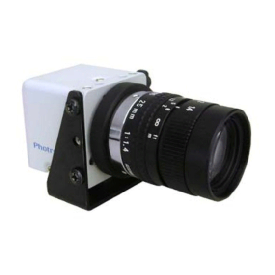
Page 22: Imager (Camera Head)
Chapter 2. Setup 2.2.4. Imager (Camera Head) The FASTCAM MC1’s imager has been designed to be smaller than the previous models. The imager has been reduced to a revolutionary small size, while maintaining high specifications such as a 512 x 512 resolution at recording rates up to 2000 fps. There are two types of interchangeable imagers;... -
Page 23: Lens Mount
2.2.6. Lens mount The basic lens mount for the FASTCAM MC1 is the C mount, which is commonly found on CCTV cameras, microscopes and so on, a wide range of different C mount lenses are available on the market. The C mount can be changed to an optional NF mount, and three different focal length NF mount lenses are available as optional accessories. -
Page 24: Lcd Monitor Keypad (Optional)
Chapter 2. Setup 2.2.7. LCD Monitor Keypad (Optional) The FASTCAM MC1’s LCD monitor keypad (optional, referred to below as the keypad) connects to the KEYPAD connector on the camera controller, and the camera can be operated using it. An LCD monitor is attached to the keypad making it possible to use the keypad as a video monitor to set up the camera and check the images. - Page 25 The FASTCAM MC1 is compatible with RS-422 control through the keypad connector. A separate command list is available for the serial control commands. Please contact Photron or the store where the system was purchased for the command list. (See: 9.1 Contracting Photron).
-
Page 26: I/O Connecters (Bnc Connectors)
Chapter 2. Setup 2.2.9. I/O Connecters (BNC connectors) By inputting an external trigger or synchronization signal, and by outputting an exposure timing or synchronization signal, these signals can be used as a part of the FASTCAM MC1 system. The input/output signal connectors, TRIGGER IN, SYNC IN and GENERAL OUT connecters, on the camera controller provide access to each type of signal. -
Page 27: Dc 18 - 36V 45Va Connector
2.2.10. DC 18 - 36V 45VA Connector The DC power supply input connector. Connect supplied AC adapter or optional High-G Battery. [DC 18 - 36V 45VA Pin Camera Controller-side Cable-side Diagram] Connector Name Signal Name Connector Model Name Connector Model Num. -
Page 28: Device Connections
Chapter 2. Setup 2.3. Device Connections 2.3.1. Connecting the Imager Follow the procedure below to connect the imager to the camera controller. 1. Verify that the camera controller’s power is off. 2. Connect the camera cable. Check the connector part of the imager and camera controller and connect as shown in the pictures below. -
Page 29: Connecting The Keypad
2.3.2. Connecting the Keypad Connect the keypad connector by inserting it into the connector labeled KEYPAD on the front of the camera controller. * The keypad is hot-pluggable. It can be plugged in and removed while the camera controller’s power is on. 2.3.3. -
Page 30: Connecting The Ac Adapter
Chapter 2. Setup 2.3.4. Connecting the AC Adapter Connect the supplied AC adapter to a power supply. Refer to the DC power item in section “7.1.2. General Specifications” for power supplies that can be used. DC 18-36V/32VA Connector AC Cable AC Adapter 1. -
Page 31: Basic Keypad Operation (Optional)
2.4. Basic Keypad Operation (Optional) The optional keypad has been designed with the intention of making frequently repeated functions easy accessible. Detailed settings have also been organized in a menu which can be efficiently operation with using the ARROW keys. This section explains the basic keypad operations when taking images with the FASTCAM MC1. - Page 32 Chapter 2. Setup ■Keypad Explanation ○ ○ ○ ○ ○ ○ ○ ○ ○ ○ ○ ○ ○ ○ ○ ○ ○ ○ ○ ○ ○ ○ Num. Key Name Function Num. Key Name Function ① ⑫ FRAME RATE Frame Rate setting SHUTTER Shutter speed setting ②...
-
Page 33: Startup Screen
2.4.2. Startup Screen 1. After attaching the imager, cables, keypad, and external devices as explained in the previous section, turn the power on by pressing the power switch on the front of the camera controller. Connect to Gigabit Ether Keypad Connect to Keypad Connect to Imager Connect to DC18-36V... - Page 34 The number of frames and the length of time that can be shot at the current setting ④ The current frame rate ⑤ The current resolution ⑥ The current shutter speed ⑦ The Photron logo ⑧ The type of the imager currently displaying LIVE images ⑨ The current time...
-
Page 35: Displaying The Menu List
2.4.3. Displaying the Menu List 1. The menu list is displayed on the video monitor screen by pressing the keypad MENU key. Submenu (BNC Cab Menu Menu List Screen 2. To leave the menu list screen without making a selection (cancel), press the MENU key or the BACK key. -
Page 36: Menu Selection/Confirmation/Cancellation
Chapter 2. Setup 2.4.4. Menu Selection/Confirmation/Cancellation The menu list has a hierarchical structure made of the “menu”, “submenu”, and “setting” layers, in that order. The cursor “ ” on the menu can be moved and the necessary menu commands can be selected by pressing the keypad ARROW keys. -
Page 37: Saving Shot Settings
2.4.5. Saving Shot Settings After using the procedure explained in “2.4.4. Menu Selection/Confirmation/Cancellation” to change settings, to save your settings for the frame rate, shutter speed, and resolution explained in “Chapter 3. Recording”, press the keypad STORE key. However, use caution as the settings below will not be saved by using STORE function. -
Page 38: Menu/Manual Reference List
Chapter 2. Setup 2.4.6. Menu/Manual Reference List The menu has the structure shown below. Submenu Manual Reference Page RECORD RANDOM FRAME P.56 MANUAL TRIGGER P.52 RESERVED ------------ ------------ RESERVED ------------ ------------ RESERVED ------------ ------------ ADJUSTMENT COLOR TEMP P.59 COLOR ENHANCEMENT P.63 LUT SELECT P.64... -
Page 39: Saving/Accessing Camera Settings
2.4.7. Saving/Accessing Camera Settings A maximum of four camera configuration settings can be saved to a FASTCAM MC1. How to save/access those settings is explained next. In addition, refer to “Chapter 3. Recording” for a detailed explanation of how to make the settings for each imager. 1. -
Page 40: Using Low Light Mode
Chapter 2. Setup 2.4.8. Using Low Light Mode As more you increase the frame rate or shutter speed of a high speed camera, the amount of light entering the camera decreases accordingly, making the displayed image dark. Low light mode is a function that temporarily increases the exposure time, making the displayed image easier to see. -
Page 41: Chapter 3. Recording
Chapter 3. Recording 3.1. Selecting the Frame Rate 3.2. Selecting the Resolution 3.3. Selecting the Shutter Speed 3.4. Selecting the Trigger Mode 3.5. White Balance Adjustment (Color Models Only) 3.6. Color Enhancement Adjustment (Color Models Only) 3.7. LUT (Look-Up Table) Operations 3.8. -
Page 42: Selecting The Frame Rate
Chapter 3. Recording 3.1. Selecting the Frame Rate Images can be captured with the FASTCAM MC1 from 60 (50 PAL) to 2000 fps using the full 512x512 pixel resolution of the image sensor. For frame rates higher than 2000 fps, high-speed photography is achieved by limiting the read area of the image sensor. - Page 43 4. The display of the number of frame and the time available for recording also changes at the same time. For frame rates over 2000 fps, the resolution is automatically set to the maximum available at that frame rate. For more details, refer to “7.1.4. Frame Rate and Resolution”. The minimum frame rate in PAL mode is 50 fps.
-
Page 44: Selecting The Resolution
Chapter 3. Recording 3.2. Selecting the Resolution Images with a maximum size of 260K pixels can be taken with the FASTCAM MC1 using the high-speed image sensor, which has a maximum size of 512x512 pixels. Also, by reducing the resolution, images can be taken with even faster frame rates, or the recording duration can be extended accordingly. -
Page 45: Selecting The Shutter Speed
3.3. Selecting the Shutter Speed In the FASTCAM MC1, the shutter speed is independent of the frame rate, and it is possible to control the exposure time for a recording using the electric shutter. By making an exposure that is of a shorter period than the frame rate, high-speed objects can be photographed blur-free. -
Page 46: Changing The Shutter Mode
Chapter 3. Recording 3.3.2. Changing the SHUTTER MODE By switching between MODE1 and MODE2 on the SHUTTER menu, SHUTTER MODE submenu, the shutter speed’s value first used when the frame rate is changed can be set. MODE1: Changing the frame rate automatically sets the shutter speed to 1/frame sec. MODE2: Changing the frame rate does not change the shutter speed, it maintains the current setting. -
Page 47: Selecting The Trigger Mode
3.4. Selecting the Trigger Mode In order to reliably capture high-speed phenomena, many kinds of trigger modes are available for the FASTCAM MC1. These trigger modes are explained next. * This explanation relates to the direct trigger mode setting (Reference:”3.15. Direct Trigger Function”) when the “READY AND TRIG”... -
Page 48: Start Mode
Chapter 3. Recording 3.4.1. START Mode START mode is a trigger mode where recording starts the instant the trigger is input, and the scene is recorded until the memory is full, and then recording ends. This mode is suitable for taking images of high-speed phenomena when what will happen, and when it happen, is known in advance. - Page 49 3. To start recording, press the REC key and the trigger is input. The screen display READY becomes REC during recording, and changes to LIVE when recording is done. Trigger Input Recording Ends 4. Recording is finished. FASTCAM MC1 Hardware Manual...
-
Page 50: Center Mode
Chapter 3. Recording 3.4.2. CENTER Mode CENTER mode is a trigger mode where equal content is recorded before and after the trigger is input is saved to memory equally. This mode is suitable for viewing before and after an important instant. - Page 51 3. Press the REC key on the keypad and the trigger is input. The screen display shows ENDLESS. This puts the system into a state where the images are continuously written to memory in a loop. 4. Press the REC key on the keypad again and the trigger is input. The screen display changes to REC.
-
Page 52: End Mode
Chapter 3. Recording 3.4.3. END Mode END mode is a trigger mode where the content recorded immediately before the trigger is input is saved to memory. This mode is suitable for recording a high-speed phenomenon where it is hard to predict when the important action will start and stop. - Page 53 4. Press the REC key once the desired action has finished. By doing this, the images immediately before the trigger is saved, and the recording operation ends. Verify that the ENDLESS display in the upper part of the screen has changed to LIVE. Trigger Input Recording Ends 5.
-
Page 54: Manual Mode
Chapter 3. Recording 3.4.4. MANUAL Mode MANUAL mode is a trigger mode, similar to CENTER mode, where the content recorded before and after the trigger is input is saved to memory, but the proportion of time before and after the trigger can be set as required. - Page 55 3. The display used to specify the before/after trigger frame count is shown on the left side of the screen. 4. The meaning of each item is explained next. -FRAME The number of frames to save BEFORE the trigger is received. +FRAME The number of frame to save AFTER the trigger is received.
- Page 56 Chapter 3. Recording 6. When the setting is complete, press the ENTER key to finish. If the setting has been made correctly, for example, an after trigger frame count of 100, the trigger mode display in the upper part of the screen will show MANUAL +100FR as shown in the image below. ■...
- Page 57 4. Press the keypad REC key again and the trigger is input. The screen display changes to REC. By doing this, the images before and after when the trigger was input are saved and the recording operation ends. Verify that the REC display has changed to LIVE. Trigger Input Recording Ends 5.
-
Page 58: Random Mode
Chapter 3. Recording 3.4.5. RANDOM Mode RANDOM mode is a trigger mode where each time a trigger is input, only a predetermined number of frames are saved to memory. For example, this function is convenient for a photographic subject which is an irregular and repeated phenomenon which can have a trigger output produced for each cycle or occurrence. - Page 59 3. The RANDOM FRAME menu is shown on the left side of the screen. Similar to the image below, this display is used to specify the number of frames to be recorded for each trigger. 4. Set the number of frames to save for one trigger input. Operate the cursor with the keypad ARROW keys to set the desired frame count.
- Page 60 Chapter 3. Recording ■ Recording in RANDOM Mode The procedure for recording in RANDOM mode is explained next. 1. Following the directions in “3.4. Selecting the Trigger Mode”, verify that the camera is in the LIVE mode and the trigger mode is RANDOM. 2.
-
Page 61: White Balance Adjustment (Color Models Only)
3.5. White Balance Adjustment (Color Models Only) On digital cameras, photographing white as pure white is described as “having the appropriate white balance.” In the FASTCAM MC1 color models as well, the white balance must be adjusted for the color temperature of the light source used, in order to take images with the correct color representation. -
Page 62: Using User White Balance
Chapter 3. Recording 3.5.2. Using User White Balance Each imager can be assigned a user white balance setting in order to achieve the most appropriate white balance for the light source used and the conditions during recording. The values set here are stored for each imager in the camera controller’s internal memory as a user preset, and the values can be loaded by selecting USER. - Page 63 7. Adjust the lens aperture and the light intensity. Verify that the value at the bottom left of the screen changes with the intensity of the light entering the camera. If the brightness on the screen is changing but the display does not, verify that the white standard object is being shot in the middle of the screen.
- Page 64 Chapter 3. Recording Making Settings with EDIT USER The white balance can be set automatically, and the user can adjust the tint by changing the RGB values. The value acquired by AUTO USER can also undergo fine adjustment. The method for using EDIT USER to make settings is explained here.
-
Page 65: Color Enhancement Adjustment (Color Models Only)
3.6. Color Enhancement Adjustment (Color Models Only) Image color enhancement level is adjusted in five steps including OFF setting, with this setting item. 1. Press MENU key on the keypad, then select the COLOR ENHANCEMENT from the ADJUSTMENT submenu and press ENTER key. 2. -
Page 66: Lut (Look-Up Table) Operations
Chapter 3. Recording 3.7. LUT (Look-Up Table) Operations The LUT (Look-Up Table) refers to a reference table that defines the relationship between the pixel brightness gradation of the original image data taken and the brightness gradation displayed on a computer screen or video monitor. The FASTCAM MC1 contains a hardware LUT function that can display the image data taken with improved contrast (light and dark sharpness), or makes an object in the image stand out by emphasizing a specified gray level range. - Page 67 D1: GAIN 1x The input is always linear output. This LUT is used for normal conditions. D2: Gamma 0.6 This LUT is 0.6 gamma correction. D3: Gamma 0.45 This LUT is 0.45 gamma correction. FASTCAM MC1 Hardware Manual...
- Page 68 Chapter 3. Recording D4: Gain 2x The upper bit from the sensor’s 8-bit input is deleted, and the remaining 7-bit data is expanded to 8-bit, which emphasize the dark areas of the image. D5: Gain 4x The upper two bits from the sensor’s 8-bit input are deleted, and the remaining 6-bit data is expanded to 8-bit, which displays the dark areas of the image emphasized.
-
Page 69: Using A Custom Lut
3.7.2. Using a Custom LUT Creating a LUT pattern is done with the PFV. For details, refer to the “Photron FASTCAM Viewer User’s Manual”. About USER A custom LUT created with PFV is used. FASTCAM MC1 Hardware Manual... -
Page 70: Edge Enhancement Function
Chapter 3. Recording 3.8. Edge Enhancement Function Edges within the recorded image are enhanced, in three steps, with the FASTCAM MC1’s edge enhancement setting. 1. Press the MENU key on the keypad, then select the EDGE ENHANCEMENT from the ADJUSTMENT submenu and press the ENTER key. 2. -
Page 71: Setting The Sensor Gain
3.9. Setting the Sensor Gain The sensor gain setting is a setting that adjusts the amplitude voltage inside the sensor. By increasing this setting, when recording in low light, the signal is amplified and the camera can take a higher gain (brighter) image. However, by amplifying the signal, the noise components also increase, resulting in decreased image quality, or more noise. -
Page 72: Input/Output Signal Types
Chapter 3. Recording 3.10. Input/Output Signal Types Many signals can be input and output with the FASTCAM MC1 using the BNC connectors. These signals are listed below. A signal other than the specified signal must not be input to the various connectors. Use extreme caution as there is a risk of damage to both devices, the input device and the output device. -
Page 73: General Out Connector
3.10.3. GENERAL OUT Connector This is also a BNC connector. The signals below can be changed and output from the menu or PFV. Refer to “3.13 GENERAL OUT Signal Settings” for details.. SYNC POS/NEG : Output a vertical synchronization signal. EXPOSEHEAD POS/NEG : Output an exposure period signal to a imager. -
Page 74: Using External Triggers
Chapter 3. Recording 3.11. Using External Triggers Recording on the FASTCAM MC1 can be done by receiving various trigger signals matched to the recording application. The trigger signals that can be used on the FASTCAM MC1 are explained here, along with a description of how to use them. 3.11.1. - Page 75 TRIGGER IN (TTL) Circuit Diagram SYNC IN Circuit Diagram TRIGGER IN (SW) Circuit Diagram MICROSD150-02 NFW31SP506X1E4 TRIG_SW__IN TRIG_SW 220ΩF 0.1μF FASTCAM MC1 Hardware Manual...
-
Page 76: Outputting External Trigger Signals
Chapter 3. Recording 3.11.2. Outputting External Trigger Signals Trigger signals can be output externally on the FASTCAM MC1 from the GENERAL OUT connector. External trigger signal output settings are also made by selecting SYNC IN/OUT from the menu, and then GENERAL OUT from the submenu. The signals are output from the GENERAL OUT connector explained in section “2.2.9. -
Page 77: Using External Synchronization Signals
3.12. Using External Synchronization Signals An external synchronization mode to enable cameras to sync an external signal is provided on the FASTCAM MC1. By using an external synchronization signal, recording can be conducted using multiple complete FASTCAM MC1 systems to synchronize the timing of the shots, or also to synchronize the shots with external measuring devices and lighting. - Page 78 Synchronize with a FASTCAM MC1 TTL level, negative polarity ON OTHERS POS Synchronize with an external device (including other Photron products) TTL level, positive polarity ON OTHERS NEG Synchronize with an external device (including other Photron products) TTL level, negative polarity Select the menu to set with the ARROW ↑↓...
-
Page 79: Outputting An External Synchronization Signal
3.12.2. Outputting an External Synchronization Signal A synchronization signal can be output externally on the FASTCAM MC1. The external synchronization signal is output from the GENERAL OUT connector explained in section “3.10. Input/Output Signal Types”. The procedure for setting external synchronization signal output is explained below. - Page 80 Chapter 3. Recording Reference (Input/Output Menu Display Content Signal Type Delay Amount) Outputs a vertical CMOS (74ACT541 buffer) SYNC POS synchronization signal Approx. 100 ns Output, Positive Polarity with positive polarity. Outputs a vertical CMOS (74ACT541 buffer) SYNC NEG synchronization signal Approx.
-
Page 81: Synchronizing Multiple Fastcam Mc1 Systems
3.12.3. Synchronizing Multiple FASTCAM MC1 Systems On the FASTCAM MC1, multiple camera controllers can be synchronized, using an external synchronization input and output, allowing synchronized shots using more than two cameras.. Conceptual Diagram of a Synchronized Connection CAMERA No.2 CAMERA No.1 (SLAVE) EXT-SYNC IN (MASTER) - Page 82 Chapter 3. Recording Setting the Master Camera Controller (Synchronization Output Controller) First, decide on which camera controller will be the master, and then set it to output the synchronization signal. 1. Press the MENU key on the keypad and the menu list will display. 2.
- Page 83 Setting the Slave Camera Controller (Synchronization Signal Receiving Controller) Next, set the synchronization signal input of the slave camera controller which will receive the synchronization signal supplied by the master camera controller. 1. Input the slave camera controller’s synchronization to the master camera controller. Connect the master camera controller’s GENERAL OUT connector and the slave camera controller’s SYNC IN connector using a BNC cable.
-
Page 84: Synchronizing The System With Other External Devices
Chapter 3. Recording 3.12.4. Synchronizing the system with Other External Devices (Frame Rate Synchronization Recording) On the FASTCAM MC1, in addition to the frame rate set on the camera, a function has been provided that can record by receiving an external synchronization signal after setting the frame rate to the frequency of the signal. - Page 85 Camera Settings 1. Input the synchronization signal from the device to be recorded into the camera. Connect the synchronizing device’s output signal to the camera controller’s SYNC IN connector using a BNC cable. 2. When the synchronization signal is input to the SYNC IN connector, the SYNC IN LED (yellow) on the front of the camera controller will light.
- Page 86 Chapter 3. Recording 7. Output the signal from the synchronization device, and verify that the camera recognizes the output frequency and synchronizes its frame rate. The recognized frame rate will display in the lower left of the video monitor. The frequency of the synchronization signal cannot be changed during the LIVE or recording state. (This is out of spec assurance.) The synchronization signal can be changed if you repeat steps 1 through 7 after changing the frequency.
-
Page 87: Synchronizing The System With Other Cameras
Using the function (frame rate synchronization recording) in the previous section, “3.12.4 Synchronizing the System with Other External Devices”, mixed-type synchronized recording can be performed with other Photron high-speed cameras (except some older products). In particular, the FASTCAM-APX RS, FASTCAM SA1 and the FASTCAM MH4-10K are also compatible with collective control by the PFV control software. -
Page 88: General Out Signal Settings
Chapter 3. Recording 3.13. GENERAL OUT Signal Settings Select a signal for output from the GENERAL OUT connector as explained in section “3.10. Input/Output Signal Types”. 1. Press the MENU key on the keypad and the menu list will display. 2. - Page 89 Menu Display Content Signal Type SYNC POS Output a positive polarity vertical synchronization signal. SYNC NEG Output a negative polarity vertical synchronization signal. EXPOSE POS Output camera image sensor’s exposure period at H level. TTL Level, Positive Polarity EXPOSE NEG Output camera image sensor’s exposure period at L level.
-
Page 90: Signal Delay
Chapter 3. Recording 3.14. Signal Delay A signal delay time or pulsewidth for the various signals that are input and output can be set on the FASTCAM MC1. The procedure for making these settings is explained here. ■TRIG TTL IN DELAY Setting Range: 0-60 (s), in 100 ns units Set from the SYNC IN/OUT submenu, TRIG TTL IN DELAY. - Page 91 ■SYNC OUT DELAY Setting Range: 0-1/frame rate (s), in 100 ns units Set from the SYNC IN/OUT submenu, SYNC OUT DELAY. The synchronization signal will be output later than normal, delayed by the amount of time set here. Increase or decrease the value with the ARROW ↑↓ keys, move the digit with the ←→ keys.
-
Page 92: Direct Trigger Function
Chapter 3. Recording 3.15. Direct Trigger Function Normally for recording, the READY key is input and the camera is put in the READY state, then the trigger is input and the recording operation is performed. However, by setting the direct trigger mode, the recording operation can be performed without the READY key input. - Page 93 Camera Operations for Each Setting ◇READY AND TRIG The READY input is always necessary before the REC trigger. This is the camera’s initial setting. ◇DIRECT TRIG The recording operation can be performed with just the REC trigger, without the READY input. Camera Operations for Each Trigger Mode in Direct Trigger [ ] indicates the camera operations, “trigger”...
-
Page 94: Using User Sw (Programmable Switch)
Chapter 3. Recording 3.16. Using USER SW (Programmable Switch) There are four switches that can be set on the front of the FASTCAM MC1 camera controller. Settings for the switches are made from the menu, and they can each be assigned a different function. -
Page 95: Status Key
3.17. STATUS Key The STATUS key is a display key that can be used to summarize and verify the status of the camera controller settings and the current status of the settings for each of the imagers. Each press of the STATUS key will display the screens below in order. 1. - Page 96 Chapter 3. Recording MEMO...
-
Page 97: Chapter 4. Playback
Chapter 4. Playback 4.1. Video Playback 4.2. Fast-Forward and Rewind Playback 4.3. Single Frame Advance Playback 4.4. Enlarging and Shrinking the Playback Screen (Zoom, Fit, Scroll) 4.5. Segment of Interest Playback 4.6. Using the Playback Event Marker Function... -
Page 98: Video Playback
Chapter 4. Playback 4.1. Video Playback The FASTCAM MC1 can immediately playback images recorded to memory on a connected video monitor or on the keypad’s LCD screen. This procedure is explained here. 1. Switch from LIVE to MEMORY mode. If the camera is in LIVE mode, press the keypad’s LIVE key to switch to playback (memory) mode. -
Page 99: Fast-Forward And Rewind Playback
4.2. Fast-Forward and Rewind Playback Set the camera into MEMORY mode. 1. Press the PLAY key (Playback 2. Press fast-forward, the FF key ( ), and rewind, the FR key ( ), to search for the desired scene. 3. Each time fast-forward, the FF key ( ), or rewind, the FR key ( ), is pressed;... -
Page 100: Single Frame Advance Playback
Chapter 4. Playback 4.3. Single Frame Advance Playback Set the camera into MEMORY mode. 1. Press the PLAY key ( 2. Press fast-forward, the FF key ( ), and rewind, the FR key ( ), to search for the desired scene. 3. -
Page 101: Enlarging And Shrinking The Playback Screen (Zoom, Fit, Scroll)
4.4. Enlarging and Shrinking the Playback Screen (Zoom, Fit, Scroll) On the FASTCAM MC1, recording is done with a sensor that has a maximum resolution of 512x512 pixels. When displaying the images on an NTSC monitor, the resolution of the image is larger vertically than the monitor resolution (640 x 480 pixels), therefore a slight portion of the top and bottom of the image will not be displayed on the monitor in the normal 1:1 display mode. -
Page 102: Video Screen Fit Display
Chapter 4. Playback 4.4.1. Video Screen Fit Display For video output on the FASTCAM MC1, the size of the image at different resolutions is adjusted so that it is displayed at its maximum size on the screen. The following example explains an example where a 512x128 pixel screen is being fit to the video screen. -
Page 103: Displaying The Video Screen Enlarged (Zoom)
4.4.2. Displaying the Video Screen Enlarged (Zoom) For video output on the FASTCAM MC1, the image can be displayed zoomed (enlarged). 1. Press the ZOOM/SCROLL key on the keypad. 2. The ZOOM key LED on the keypad will light. The ZOOM message and the current zoom factor will also be displayed in the upper right of the video output screen. -
Page 104: Scrolling The Video Screen
Chapter 4. Playback 4.4.3. Scrolling the Video Screen For video output on the FASTCAM MC1, the image can be displayed zoomed (enlarged). 1. Press the ZOOM/SCROLL key on the keypad. This button is shared with the zoom function, so verify that the SCROLL key LED on the keypad is illuminated. 2. -
Page 105: Segment Of Interest Playback
4.5. Segment of Interest Playback The playback of images shot at high-speed takes an extraordinary amount of time. For example, when played back at a normal 30 fps, one second of video shot at high-speed at 2000 frames a second takes 66 seconds to playback, in other words, over a minute of playback time. In many cases, the desired range of images is only a few images out the recorded 2000. -
Page 106: Using The Playback Event Marker Function
Chapter 4. Playback 4.6. Using the Playback Event Marker Function During MEMORY mode, 10 playback image frame numbers can be stored, and those stored frame numbers (event marker frame) can be immediately accessed, or jumped to. By marking the desired position while the image is played back, this convenient function can easily recall those positions. -
Page 107: Chapter 5. Connecting A Pc
Chapter 5. Connecting a PC 5.1. Connecting a PC to the Camera Controller’s Gigabit Ether Interface... -
Page 108: Connecting A Pc To The Camera Controller's Gigabit Ether Interface
Connecting the FASTCAM MC1 and a PC (a personal computer) is explained here. On the FASTCAM MC1, the operation of the camera functions can be controlled from a PC using the Gigabit Ether interface. Refer to the “Photron FASTCAM Viewer User’s Manual” for how to operate the software camera controller. -
Page 109: Connecting The Fastcam Mc1 And A Pc
5.1.1. Connecting the FASTCAM MC1 and a PC Connect the LAN cable to the FASTCAM MC1 as shown below. Push the LAN cable into the connector. FASTCAM MC1 Hardware Manual... -
Page 110: Setting The Camera Controller's Ip Address
Chapter 5. Connecting a PC 5.1.2. Setting the Camera Controller’s IP Address The procedure for setting the camera controller’s IP address is shown below. Setting Procedure 1. Press the MENU key on the keypad and the menu list will display. 2. -
Page 111: Using Dhcp (Dynamic Host Configuration Protocol)
DIGITAL I/F SET menu. In this case, the IP address cannot be changed. When using the system with DHCP on, set the IP address on the PFV to “Auto detection”. For details, refer to the “Photron FASTCAM Viewer User’s Manual”. FASTCAM MC1 Hardware Manual... -
Page 112: Connecting The Pc To Multiple Cameras
With PFV3, the FASTCAM MC1 control software, one PC can connect to and control, multiple FASTCAM MC1 or other Photron hi-speed camera systems which have Gigabit Ether interface. When connecting to multiple systems, set the IP address of each camera to a unique setting. -
Page 113: Chapter 6. System Settings
Chapter 6. System Settings 6.1. Display Settings 6.2. Other Detailed Settings... -
Page 114: Display Settings
Chapter 6. System Settings 6.1. Display Settings In addition the image, the FASTCAM MC1 can display many types of information necessary for recording on the video monitor. The procedure for setting the display of this information on the video monitor is explained here. 6.1.1. -
Page 115: Display/Hide On Screen Display (Osd) Text
6.1.2. Display/Hide On Screen Display (OSD) Text 1. Press the MENU key on the keypad and the menu list will display. 2. Select OSD SELECT from the DISPLAY submenu with the ARROW keys and press the ENTER key. 3. Select ON/OFF with the ARROW keys. When ON, text on the screen is displayed. When OFF, text on the screen is not displayed. - Page 116 Chapter 6. System Settings 2. Select CURSOR from the DISPLAY submenu with the ARROW keys on the keypad and press the ENTER key. 3. Select either OFF, ON1, or ON2 with the ↑↓ keys on the keypad, and press the ENTER key.
-
Page 117: Display R/G/B Plane (Color Models Only)
6.1.4. Display R/G/B Plane (Color Models Only) 1. Press the MENU key on the keypad and the menu list will display. 2. Select R/G/B from the DISPLAY submenu with the keypad ARROW keys and press the ENTER key. 3. Select the R/G/B element to be displayed, or to display all of the RGB elements with the keypad ↑↓... -
Page 118: Select The Video Signal Standard (Ntsc Or Pal)
Chapter 6. System Settings 6.1.5. Select the Video Signal Standard (NTSC or PAL) Select the FASTCAM MC1’s video output signal standard. The standard can be selected from NTSC or PAL. 1. Press the MENU key on the keypad and the menu list will display. 2. -
Page 119: Keypad Lcd Settings
6.1.6. Keypad LCD Settings There are three settings for the keypads LCD display, BRIGHT (brightness), CONTRAST (contrast), and COLOR (tint). 1. Press the MENU key on the keypad and the menu list will display. 2. Select KEYPAD from the DISPLAY submenu with the keypad ARROW keys and press the ENTER key. -
Page 120: Other Detailed Settings
Chapter 6. System Settings 6.2. Other Detailed Settings 6.2.1. Setting the Date/Time Set the FASTCAM MC1’s internal clock. Set the date or time, it can be displayed within the recorded image. Once the date/time is set, the entered values are saved even when the system power is turned off. -
Page 121: Post-Recording Auto-Playback Setting (Auto Play)
6.2.2. Post-Recording Auto-Playback Setting (AUTO PLAY) The FASTCAM MC1 is equipped with a mode that automatically switches the system from LIVE mode to MEMORY (playback) mode, displays the trigger frame and pauses the playback immediately the recording is finished. This mode can be used by setting AUTO PLAY to ON. This function is convenient for immediately verifying the recorded video after recording. -
Page 122: Reset To Factory Default State
Chapter 6. System Settings 6.2.3. Reset to Factory Default State The settings (frame rate, resolution, menu settings, etc.) on the FASTCAM MC1 can be reset to the factory default state. Setting Procedure 1. Press the MENU key on the keypad and the menu list will display. 2. -
Page 123: Display The System Revision
6.2.4. Display the System Revision Displays the system version number for the FASTCAM MC1. 1. Press the MENU key on the keypad and the menu list will display. 2. Select SYSTEM REV from the OTHERS submenu with the keypad ARROW keys and press the ENTER key. - Page 124 Chapter 6. System Settings MEMO...
-
Page 125: Chapter 7. Product Specifications
Chapter 7. Product Specifications 7.1. Specifications 7.2. Dimensions... -
Page 126: Specifications
Chapter 7. Product Specifications 7.1. Specifications 7.1.1. Product Specifications Image Sensor CMOS image sensor Sensor Resolution 512 x 512 pixels Frame Rate 2,000 fps full frame Lens Mount C mount, (NF mount is optional) Monochrome 8-bit Recording Color Depth Color RGB, each 8-bit (Bayer color filter method) Shutter Electronic shutter... -
Page 127: General Specifications
Keypad 1310 g. 46.2 Oz Photron has verified two types of AC cables, the type A (standard for Japan, USA, Canada, etc.) and the type SE (standard for Germany, France, etc.). However, when those cables cannot properly receive power when plugged in, user the proper AC cable for the region’s standards, and verify that AC cable works properly. -
Page 128: Options
Chapter 7. Product Specifications 7.1.3. Options User Options Battery Power Supply Unit LCD Monitor Keypad NF Mount / NF mount Lenses (3.5mm, 6mm, 12 mm focal lengths) Dedicated Carrying Case Extra Imager (monochrome/color) -
Page 129: Frame Rate And Resolution
7.1.4. Frame Rate and Resolution Maximum Settable Resolution Frame Resolution 512 x 512 x 512 x 512 x Rate (fps) 512 x 96 50 (PAL) 512 x 512 1000 2000 512 x 352 3000 512 x 256 4000 5000 6000 512 x 128 7000 8000... -
Page 130: Recordable Image Count/Resolution
Chapter 7. Product Specifications 7.1.5. Recordable Image Count/Resolution Recordable image count with 1 Recordable image count with 2 Resolution GB of memory GB of memory 512 x 512 4092 8188 512 x 352 5952 11909 512 x 256 8184 16376 512 x 128 16368 32752... -
Page 131: Dimensions
7.2. Dimensions 7.2.1. Camera Controller All dimensions are in Millimeters (mm) – 25.4 mm equal one inch. These diagrams are not shown to scale. 22.5 29.5 107.5 165.5 132.9 FASTCAM MC1 Hardware Manual... -
Page 132: Imager
Chapter 7. Product Specifications 7.2.2. Imager All dimensions are in Millimeters (mm) – 25.4 mm equal one inch. These diagrams are not shown to scale. 4*2*M3 DEPTH3 9.33 39.83 φ34 45.01... -
Page 133: Lcd Monitor Keypad
7.2.3. LCD Monitor Keypad All dimensions are in Millimeters (mm) – 25.4 mm equal one inch. These diagrams are not shown to scale. 28.3 PRESET1 PRESET2 PRESET3 PRESET4 FRAME RATE RESOLUTION SHUTTER TRIGGER MODE PLAY PAUSE STOP HEAD SELECT LOW LIGHT PARTITION/ PLAYBACK RATE MENU BACK... - Page 134 Chapter 7. Product Specifications ■ Dimensions with Attached Hood 154.4 88.1 PRESET1 PRESET2 PRESET3 PRESET4 FRAME RATE RESOLUTION SHUTTER TRIGGER MODE PLAY PAUSE STOP HEAD SELECT LOW LIGHT PARTITION/ PLAYBACK RATE MENU BACK ZOOM SCROLL SLOW FAST ENTER FIT/1:1 VBS/SDI STORE STATUS SEGMENT PLAYBACK...
- Page 135 ■ Dimensions with Tripod Adapter 154.4 88.1 PRESET1 PRESET2 PRESET3 PRESET4 FRAME RATE RESOLUTION SHUTTER TRIGGER MODE PLAY PAUSE STOP HEAD SELECT LOW LIGHT PARTITION/ PLAYBACK RATE MENU BACK ZOOM SCROLL SLOW FAST ENTER FIT/1:1 VBS/SDI STORE STATUS 1/4-inch screw SEGMENT PLAYBACK LIVE REC READY...
-
Page 136: Ac Adapter
Chapter 7. Product Specifications 7.2.4. AC Adapter All dimensions are in Millimeters (mm) – 25.4 mm equal one inch. These diagrams are not shown to scale. 1500... -
Page 137: Chapter 8. Warranty
Chapter 8. Warranty 8.1. About the Warranty... -
Page 138: About The Warranty
5. Consumable goods (battery, cables) 6. When repair, adjustment, or alternation done by an entity other than Photron service has been performed on the system, or damage or malfunction that is determined to be a result of the responsibility of using the product. -
Page 139: Chapter 9. Contacting Photron
Chapter 9. Contacting Photron 9.1. Contacting Photron... -
Page 140: Contacting Photron
Chapter 9. Contacting Photron 9.1. Contacting Photron For technical inquires related to the system, or for inquires related to the user’s manual, telephone, FAX, or e-mail using the contact information listed below. In addition, the following items will be verified when inquiring, so note them in advance. - Page 141 P u b l i s h e r P H O T R O N L I M I T E D 21F, Jimbocho Mitsui Bldg., 1-105 Kanda Jimbocho, Chiyoda-Ku, Tokyo 101-00511 ©2007. PHOTRON LIMITED, All rights reserved. Control No. E201180521 H...
Need help?
Do you have a question about the FASTCAM MC1 Series and is the answer not in the manual?
Questions and answers