Table of Contents
Advertisement
Advertisement
Table of Contents

Related Manuals for Photron FASTCAM MH6


Summary of Contents for Photron FASTCAM MH6
- Page 1 FASTCAM MH6 Hardware Manual...
- Page 2 The copyright of this manual is held by PHOTRON LIMITED. Product specifications and manual contents are subject to change without notice. PHOTRON LIMITED bears no responsibility for any results by using our products nor by applying this manual to any operations.
- Page 3 This manual contains the operating instructions and warnings necessary for using the system. Before using the system, please read the entire manual. If any part of this manual is unclear, contact Photron using the contact information printed at the back of the manual.
- Page 4 This chapter explains the system’s specifications. Chapter 4, Product Specifications This chapter explains about the warranty. Chapter 5, Contacting Photron This chapter lists the contact information to use when contacting Photron if the system malfunctions or if a portion of the manual is unclear.
- Page 5 Manual Notation The following icons and symbols are used in the explanations in this manual. Icon/Symbol Description This symbol indicates supplementary items to be aware of when using the software. This symbol indicates the location of a reference. This symbol indicates content that should always be read. This symbol indicates instructions that should always be followed when using the software, or things to be careful of when using the software.
- Page 6 In order to prevent injury to yourself and others, and to prevent damage to property, carefully observe the following safety precautions. Photron has given its full attention to the safety of this system. However, the extent of damage and injury potentially caused by ignoring the content of the safety precautions and using the system incorrectly is explained next.
- Page 7 Warning ■Do not perform actions that will damage the AC cable or plug. (Do not damage the cable, modify it, use it near a heater, excessively bend, twist or pull on it, place heavy objects on it, or bundle it.) Using the cable when damaged can cause fire, electric shock, or a short circuit.
- Page 8 Caution ■Always unplug the system when cleaning it or when it is unused for a long period of time. Leaving or storing the system connected to the power source might cause fire from insulation deterioration or electrical discharge. ■Please consult us in advance when you perform an event by which laser light or direct rays fall on the image sensor surface.
- Page 9 Caution ■When installing the camera with a tripod, please check the tripod load capacity and be careful not to exceed the load bearing capacity. Also, when using a tripod, please make sure that the tripod, tripod screw, panhead, and others are properly set, and be careful not to fall down the tripod...
- Page 10 For more information about the recycling of this product, please contact your local city office, waste authority, approved scheme or your household waste disposal service or visit www.photron.com. (EEA: Norway, Iceland and Liechtenstein) This product is in conformity with the protection requirements of EU Council Directive 2014/30/EU (Class A) on the approximation of the laws of the Member States relating to electromagnetic compatibility.
- Page 11 Cleaning of the Image Sensor Surface Electrostatic Discharge (ESD) events may cause immediate and unrecoverable damage to the image sensor. Please read the following instructions and take EXTREME CARE when cleaning the image sensor surface. ■ALWAYS take appropriate anti-static precautions when cleaning or working near the Image sensor.
-
Page 12: Table Of Contents
Contents Setup 1.1. About the System’s Components and Accessories ......... 2 Components ................2 1.1.1. Accessories/Options ............... 2 1.1.2. Type ..................3 1.1.3. 1.2. Part Names ..................4 Main Unit ................4 1.2.1. Main Unit Part Names ............. 5 1.2.2. CameraHead ................ - Page 13 Power Supply Unit ............... 32 3.2.1. I/O 2 PORT Cable ..............32 3.2.2. Contacting Photron 4.1. About the Warranty ................ 34 Contacting Photron 5.1. Contact Information ................ 36 A. Appendix A.1. Reference Information ..............38 A.1.1. Relative Spectral Response (monochrome) ......38 A.1.2.
-
Page 14: Setup
Setup This chapter gives an overview of the components that make up the system. It also explains a list of items that should be checked before using the system. -
Page 15: About The System's Components And Accessories
Camera Cable for MH6 (9m/6m) Cable Removal Prevention Cap Connection Cable for Hi-G Battery (7m/3m) Hi-G Battery (32V type/24V type) FASTCAM MH6 Specialized Carrying Case • The composition of cables turns into composition chosen at the time of purchase. FASTCAM MH6... -
Page 16: Type
When purchasing, it is possible to select the Camera head type and the number of heads according to the application or your demands. The type categories are listed as follows. ◼ Camera head type name and category FASTCAM MH6 Camera Head type 10K-C 1000K-C-64GB Frame Rate Camera Name Censor... -
Page 17: Part Names
Part Names The system is composed of components including the Main Unit, Camera Head, AC Power Supply Unit, and the "Photron FASTCAM Viewer" controls software (referred to below as PFV). For the camera body and the AC power adapter Do not expose the camera body, AC power adapter and other optional components to shock. -
Page 18: Main Unit Part Names
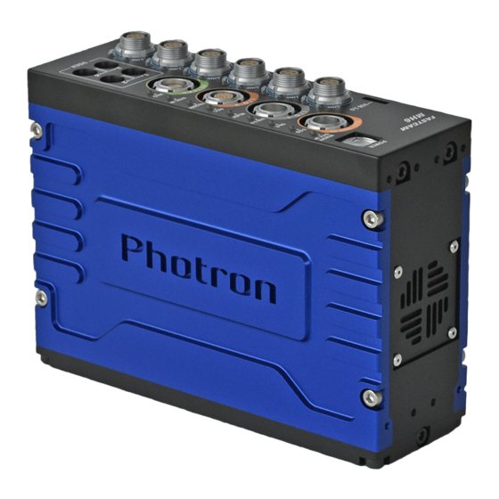
USB 3.0 DC22-32V 135VA IN USB 3.0 Connector Power Supply Connector I/O PORT 1 I/O Port Connector Gigabit Ethernet Connector Camera Connector I/O PORT 2 I/O Port Connector KEYPAD Remote keypad Connector Status Indicator LED USER USER SW1~4 FASTCAM MH6... -
Page 19: Camerahead
また、1台の Main Unit に対し複数接続可能なカメラヘッドは、共通の同期信号にて動作するため、1つの 現象を様々な角度から同時撮影することが可能です。 Camera Head • Since the camera head is not compatible with hot plug, please remove it before turning off the main power. Please note that it will cause malfunction if you turn the power on. FASTCAM MH6... -
Page 20: Camerahead+Bracket
A different Hi-G lens Bracket is prepared for each lens. Please use the Hi-G lens bracket corresponding to each lens. Lenses corresponding to the following brackets LM6HC:KOWA FASTCAM MH6... - Page 21 Below is an example of the procedure for attaching the camera head bracket. 1. Paste gasket. 2. Use M3 x depth6 hex socket cap bolts to attach to the left and right sides. 3. Use M3 × depth6 flat head screws on top. FASTCAM MH6...
- Page 22 5. Use M4 × depth10 hex socket cap bolt and M4 × depth10 hex socket cap bolt. M4×10 hex socket cap bolt M4×10 hex socket cap bolt with M4 washer 6. Use knurled screw and M3 × depth4 bind (both sides) to install the parts. Knurled screw M3×4 bind (両側) Completion FASTCAM MH6...
- Page 23 ◼ Main Unit with Hi-G Bracket ◼ Hi-G Cable Fix Handle FASTCAM MH6...
-
Page 24: Gigabit Ethernet Connector
The maximum cable length between the PC and the system is, compliant to the 1000BASE-T specification, up to 100 m. One PC can connect to a maximum of 64 Photron Gigabit Ethernet interface equipped cameras using a hub. When connecting multiple devices, connect through a switching hub that can connect at 1000BASE-T. - Page 25 • When using the above signals, it is necessary to create a cable with reference to the table. • Sync R, Sync F, Trig R, Trig F has no termination. Sync R, Sync F can be single input. • For other details, please contact our technical staff. • FASTCAM MH6...
- Page 26 • Photron recommends using an STP cable over long distances or in noisy locations. • The system's factory default IP address is below: IP ADDRESS : 192.168.0.10 NETMASK : 255.255.255.0 GATEWAY ADDRESS : 0.0.0.0 FASTCAM MH6...
-
Page 27: Vda_Trig Sync Circuit Diagram
1.2.6. VDA_TRIG SYNC Circuit Diagram FASTCAM MH6... -
Page 28: Io Input_If Circuit Diagram
1.2.7. IO INPUT_IF Circuit Diagram FASTCAM MH6... -
Page 29: Recording
Recording This chapter explains operations related to recording. -
Page 30: Selecting Frame Rate/ Resolution
• At a frame rate faster than 750fps, the resolution is also set to the maximum resolution that can be selected at that frame rate at the same time. For details, refer to "3.1.3 Frame Rate and Resolution", page 22. FASTCAM MH6... -
Page 31: Selecting Shutter Speed
1/1,000 (1msec), and when the frame rate is 1,000 fps or higher, it can be changed from one step shorter shutter speed than '1/frame' second to maximum 1/4,800,000 second (0.2usec) (it depends on the setting). • For more information of Shutter Speed, refer to “3.1.4. Shutter Speed List”, page 23. FASTCAM MH6... - Page 32 Product Specifications This chapter explains the system’s specifications.
-
Page 33: Product Specifications Specifications
I/O1: RS485 (not termination) or +5Vp-p Positive/Negative polarity (switchable) Trigger Input Signal I/O2: TTL +3.3 to +12Vp-p Positive/Negative polarity (switchable), contact Other Output Signals Other timing signal outputs External Control Gigabit Ethernet IF(PC), USB3.0 Digital Interface Gigabit Ethernet(1000BASE-T), USB3.0 FASTCAM MH6... -
Page 34: General Specifications
AC Adapter 670g Photron has verified two types of AC cables, type A (standard for Japan, USA, Canada, etc.) and type SE (standard for Germany, France, etc.). However, when those cables cannot properly receive power when plugged in, use the proper AC cable for the region's standards and verify that AC cable works properly. -
Page 35: Frame Rate And Resolution
○ 1600 ○ ○ ○ ○ ○ ○ ○ 2000 ○ ○ ○ ○ ○ ○ 2640 ○ ○ ○ ○ ○ 3000 ○ ○ ○ ○ 4000 ○ ○ 5000 ○ ○ 6000 7000 8000 9000 10000 FASTCAM MH6... -
Page 36: Shutter Speed List
9,320 18,641 37,282 800x600 8,947 13,421 26,843 53,686 640x480 13,981 20,971 41,943 83,886 512x512 16,384 24,576 49,152 98,304 512x256 32,768 49,152 98,304 196,608 320x240 55,924 83,886 167,772 335,544 * Recording Time = Rec. Frames x 1/frame rate (fps) FASTCAM MH6... - Page 37 • The number of images that can be recorded varies depending on the connected PORT. It is recommended to use the following combination. 6 Heads: CAM 1 to CAM 6 4 heads: CAM 1 to 2, CAM 4 to 5 2 heads: CAM 1, CAM 4 1 Head: CAM 1 FASTCAM MH6...
-
Page 38: Dimensions
Dimensions 3.2.1. Main Unit (mm) (7.5) (27.5) 4-M4×6 4-M4×6 FASTCAM MH6... -
Page 39: Main Unit With Hi-G Brackets
3.2.2. Main Unit with Hi-G Brackets (mm) Right Side Vidw Front View FASTCAM MH6... -
Page 40: Camerahead
3.2.3. CameraHead (mm) Top View (102.1) (66.1) 8-M3 DEPTH2.5 1000±5 35.4 40.4 Front View Right Side View 17.77(Image Sensor Position) 0.7(Sensor Cover Glass) Sensor Position Bottom View FASTCAM MH6... -
Page 41: Camerahead With Hi-G Bracket
3.2.1. CameraHead with Hi-G Bracket (mm) Top View 101.66 97.35 Left Side View FASTCAM MH6... -
Page 42: Hi-G Bracket
3.2.1. Hi-G Bracket Hi-G Bracket (Side A) (mm) 2-M3 Depth3 Diameter of drilling4 59.5 55.5 42.3 39.5 A A 4-M4 Through tap 2-M3 Depth3 Diameter of drilling4 FASTCAM MH6... - Page 43 Hi-G Bracket (Side B) (mm) 53.5 2-M3 depth6 through tap8.5 Hi-G Bracket (Bottom) (mm) A A 6.5(2places) 18.5 55.4 92.4 2-φ6.5 1/4inch helisad 1D SEC.A-A 76.9 21.4 15.5 FASTCAM MH6...
- Page 44 Hi-G Bracket (Top) (mm) 39.5 Hi-G Bracket (Front) (mm) +0.3 φ43 SEC.B-B 40.8 36.4 10.25 M2.6X4.5-SUS303 irisert 5.25 A 2-M3 through tap B B A Sculpture letters Inking (white) Sculpture letters SEC.A-A Inking (white) FASTCAM MH6...
-
Page 45: Power Supply Unit
3.2.1. Power Supply Unit (mm) 3.2.2. I/O 2 PORT Cable TRIG TTL IN TRIG TTL OUT TRIG SW IN S Y N C GENERAL IN GENERAL OUT1 GENERAL OUT2 GENERAL OUT3 T R I G I/O cable FASTCAM MH6... -
Page 46: Contacting Photron
Contacting Photron... -
Page 47: About The Warranty
Consumable goods (cables) ④ When repair, adjustment, or alternation done by an entity other than Photron service has been performed on the system, or damage or malfunction that is determined to be attributed to a fault in the use the product. -
Page 48: Contacting Photron
Contacting Photron This chapter lists the contact information to use when contacting Photron if the system malfunctions or if a portion of the manual is unclear. -
Page 49: Contact Information
Contact Information For inquiries related to FASTCAM MH6, contact Photron at one of the contact points listed below. Additionally, the following items will be required for verification when inquiring. You are kindly asked to prepare them in advance. Items Verified... -
Page 50: Appendix
A. Appendix... -
Page 51: Reference Information
• The spectrum response curve is a nominal (a reference) data of the monochrome image sensor device. A.1.2. Relative Spectral Response (color) • The spectrum response curve is a nominal (a reference) data of the color image sensor device. FASTCAM MH6... - Page 52 FASTCAM MH6 Hardware Manual Revision 4.00E Publication Date: November,2018 Publisher: PHOTRON LIMITED 21F, Jimbocho Mitsui Bldg., 1-105 Kandajimbocho, Chiyoda-Ku, Tokyo 101-0051 © 201 8.P H O TR ON LI MI TE D , Al l r ights res er ved . P rin ted in Ja pan.
Need help?
Do you have a question about the FASTCAM MH6 and is the answer not in the manual?
Questions and answers