Photron FASTCAM SA-Z Hardware Manual
Hide thumbs
Also See for FASTCAM SA-Z:
- First step manual (36 pages) ,
- Hardware manual (74 pages) ,
- Connection manual (53 pages)
Table of Contents
Advertisement
Quick Links
Advertisement
Table of Contents

Related Manuals for Photron FASTCAM SA-Z


Summary of Contents for Photron FASTCAM SA-Z
- Page 2 • This manual was created taking every possible measure to ensure the accuracy of its contents. However, if you find a section which is unclear, a mistake, or an omission, please contact PHOTRON LIMITED using the contact information provided at the end of the manual. • PHOTRON LIMITED bears no responsibility for the results of using the product or from following the instructions in this manual.
- Page 3 This manual contains the operating instructions and warnings necessary for using the system. Before using the system, please read the entire manual. If any part of this manual is unclear, contact Photron using the contact information printed at the back of the manual.
- Page 4 This chapter explains operations related to recording. • Chapter. 4 Connecting a PC This chapter explains the procedure for connecting the system to a PC. Refer to the “Photron FASTCAM Viewer User’s Manual” for additional details on using a PC to control the system. •...
- Page 5 In order to prevent injury to yourself and others, and to prevent damage to property, carefully observe the following safety precautions. Photron has given its full attention to the safety of this system. However, the extent of damage and injury potentially caused by ignoring the content of the safety precautions and using the system incorrectly is explained next.
- Page 6 ■ Do not plug in or unplug the power cord with wet hands. Doing so can cause electric shock. ■ This chapter lists the contact information to use when contacting Photron if the system malfunctions or if a portion of the manual is unclear.
- Page 7 Caution ■ Always unplug the system when cleaning it or when it is unused for a long period of time. Leaving or storing the system connected to the power source might cause fire from insulation deterioration or electrical discharge. ■Please consult us in advance when you perform an event by which laser light or direct rays fall on the image sensor surface.
- Page 8 For more information about the recycling of this product, please contact your local city office, waste authority, approved scheme or your household waste disposal service or visit www.photron.com. (EEA: Norway, Iceland and Liechtenstein) This product is in conformity with the protection requirements of EU Council Directive 2014/30/EU (Class A) on the approximation of the laws of the Member States relating to electromagnetic compatibility.
- Page 9 Cleaning of the Image Sensor Surface Electrostatic Discharge (ESD) events may cause immediate and unrecoverable damage to the image sensor. Please read the following instructions and take EXTREME CARE when cleaning the image sensor surface. ■ ALWAYS take appropriate anti-static precautions when cleaning or working near the Image sensor.
-
Page 10: Table Of Contents
Table of Contents Chapter. 1 Overview 1.1. Product Overview and Features ................2 Chapter. 2 Setup 2.1. About the System’s Components and Accessories ..........4 2.1.1. Components ....................4 2.1.2. Accessories/Options ................... 4 2.1.3. Type ......................5 2.2. Part Names ......................6 2.2.1. - Page 11 3.19.2. Outputting an External Synchronization Signal ........55 3.19.3. Synchronization with a variable frequency ..........56 3.19.4. Synchronizing Multiple FASTCAM SA-Z Systems ........57 (Multiple Unit Synchronized Recording) ..............57 3.19.5. Synchronizing the System with Other External Devices ......59 (Frame Rate Synchronized Recording) ..............
- Page 12 Camera Body .................... 96 5.2.2. Remote Controller (Optional) ..............100 5.2.3. Remote Controller with LCD (Optional) ..........101 5.2.4. AC Power Supply Unit ................102 Chapter. 6 Warranty 6.1. About the Warranty ....................104 Chapter. 7 Contacting Photron 7.1. Contact Information ....................106...
-
Page 13: Chapter. 1 Overview
Chapter. 1 Overview 1.1. Product Overview and Features FASTCAM SA-Z Hardware Manual... -
Page 14: Product Overview And Features
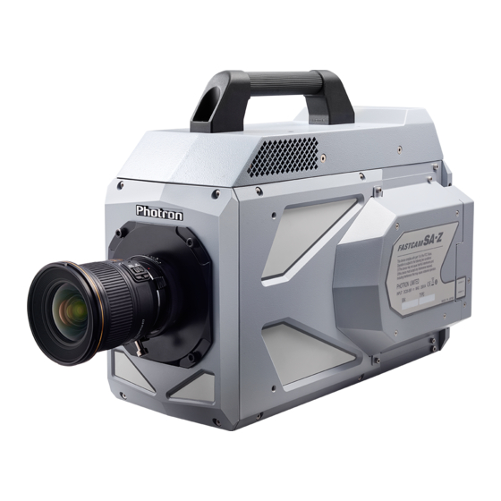
1.1. Product Overview and Features The FASTCAM SA-Z is a powerful engineering tool for use in research and development, design, production, and quality control, and in numerous fields such as science, medicine, biology, aviation and space. The system features superior basic performance with mega pixel resolution, an ultra-sensitive image sensor capable of clear recording in low-light, and an ultra-high speed frame, rate of a maximum of 480,000 fps (frame per second). -
Page 15: Chapter. 2 Setup
Chapter. 2 Setup 2.1. About the System’s Components and Accessories 2.2. Part Names 2.3. Device Connections FASTCAM SA-Z Hardware Manual... -
Page 16: About The System's Components And Accessories
The following options are available for the system. Remote Controller for SA8/SA-X/SA-X2/SA-Z Remote Controller with LCD for SA-X2/SA-Z EF Remote Controll Mount Option for SA-Z FASTCAM SA-Z Specialized Carrying Case Photron Trigger Box Mount with Filter changer(3 type) Mount with Filter changer(1 type) -
Page 17: Type
2.1.3. Type For the FASTCAM SA-Z system, there are monochrome and color versions, and for each of these versions, there are 8 GB standard memory capacity type and 16 GB (or 32GB, 64GB) high capacity type. When purchasing, it is possible to select from these models according to the application or your demands. -
Page 18: Part Names
2.2. Part Names The system is composed of components including the camera body, AC power supply, and the "Photron FASTCAM Viewer" control software (referred to below as PFV). For each of the system components. - Do not expose to shock. - Page 19 Apperance Rear FASTCAM SA-Z Apperance Rear FASTCAM SA-Z FAST Drive model FASTCAM SA-Z Hardware Manual...
-
Page 20: Camera Body Part Names
Chapter. 2 Setup 2.2.2. Camera Body Part Names FASTCAM SA-Z Handle G type F Mount Front Front Handle Status Indicator LEDs POWER SW Power Switch USER SW GIGABIT ETHER Programmable Switch Gigabit Ethernet LAN Cable Connector KEYPAD KEYPAD Connector VIDEO OUT... - Page 21 FASTCAM SA-Z FAST Drive model Handle FAST Drive Mount G type F Mount Front Front Handle POWER SW Power Switch Status Indicator LEDs GIGABIT ETHER Gigabit Ethernet USER SW LAN Cable Connector Programmable Switch FAST Drive KEYPAD Mount Front Locks...
-
Page 22: Status Display Leds On The Rear Of The Camera Body
Chapter. 2 Setup 2.2.3. Status Display LEDs on the Rear of the Camera Body There are a number of LEDs on the rear of the system's camera body. These LEDs indicate the status of the system. The function of each LED is explained here. ... - Page 23 During the Gigabit Ethernet interface initialization LEDs other than POWER (green) and IF LINK/TRANS (red) blink alternately from right to left and from left to right a number of times. • For how to initialize the Gigabit Ethernet interface, refer to "4.1.7. Gigabit Ethernet Interface Initialization", page 77. FASTCAM SA-Z Hardware Manual...
-
Page 24: Interchangeable Lens Mounts
Chapter. 2 Setup 2.2.4. Interchangeable Lens Mounts The lens mount on the system can be changed according to the recording purpose. There are 3 types of interchangeable lens mounts: “G type F-mount”, “C-mount”, and “EF mount(Option)”. The system has mechanical shutter as a standerd feature. •... -
Page 25: Remote Controller (Optional)
ECG.2B.310.CLN S22L0C-P10MJG0-820S KEYPAD Keypad signal (LEMO) (ODU) • The remote controller is optional. It is not included in the standard configuration. • For how to operate of the Remote Controller, refer to "Remote Controller User's Manual". FASTCAM SA-Z Hardware Manual... -
Page 26: Serial Control
For details, check the command list. Serial control commands are available as separate list of commands. Please contact Photron or the dealer where the system was purchased regarding the command list. A cable is also not offered as an accessory. When using RS-422 control, construct a cable using the pin diagram below for reference. -
Page 27: I/O Port Connector
TRIG SW IN SYNC IN I/O PORT (Camera Body) GENERAL IN GENERAL OUT1 GENERAL OUT2 GENERAL OUT3 ECJ.2B.326.CLD IRIG IN • For the signal which can be inputted, refer to “3.17. Input / Output Signal types”, page 50. FASTCAM SA-Z Hardware Manual... - Page 28 Chapter. 2 Setup Camera Body Conector Input Connector Cable Connector Model Signal Name model No. Conector Name No. (Manufacturer) (Manufacturer) (Pin No.) GENERAL OUT2 GENERAL OUT3 RESERVE RESERVE RESERVE RESERVE RESERVE IRIG GND IRIG SYNC IN TRIGGER TTL IN TRIGGER TTL OUT ECJ.2B.326.CLD FGJ2B326CLLD92Z I/O PORT...
-
Page 29: Power Supply Connector
Please use a external power supply with the suitable rating which was estimated by Warning IEC/EN 61010-1 3 Edition (compiled with CI. 6.3 and CI. 2.5), and separated from the main circuit by double insulation or reinforced insulation FASTCAM SA-Z Hardware Manual... -
Page 30: Sd Memory Card Slots
Chapter. 2 Setup 2.2.9. SD Memory Card Slots These slots are for an SD Memory Card to save image data. Insert an SD Memory Card which is on the market. Recorded image data can be saved on an SD card and the saved data can be played and converted to other formats by "PFV". -
Page 31: Device Connections
(Color bars are a reference guide). • One of the connectors can switch the output signal between Live mode and Memory mode, and the other connector will always output Live signal simultaneously. • Use 5C-FB specification cables for HD SDI output. FASTCAM SA-Z Hardware Manual... -
Page 32: Connecting The Ac Power Supply
Chapter. 2 Setup 2.3.2. Connecting the AC Power Supply Connect the supplied AC power supply unit to the power supply. 1, 5 Confirm the Power SW is turned off. Connect the AC power supply unit to the “DC20-36V 230VA” connector on the back of the camera body. -
Page 33: Connecting The Keypad (Optional)
"KEYPAD" on the rear of the camera body. 『VIDEO OUT terminal』 • The Keypad is hot-pluggable. It can be plugged in and removed while the system's power is on. • For how to operate of the Keypad, refer to "Remote Keypad User's Manual". FASTCAM SA-Z Hardware Manual... -
Page 34: Connecting A Pc
The maximum cable length between the PC and the system is 100 m (compliant to the 1000BASE-T specification). One PC can connect to a maximum of 64 Photron Gigabit Ethernet interface equipped cameras using a hub. When connecting multiple devices, connect through a switching hub that can connect at 1000BASE-T. -
Page 35: Chapter. 3 Recording
3.13. Look-Up Table (LUT) Operations 3.14. Edge Enhancement Function 3.15. Partition Memory & Record 3.16. Simultaneous Replay/Record Function 3.17. Input / Output Signal Types 3.18. Using External Triggers 3.19. Using External Synchronization Signals 3.20. GENERAL Signal Settings FASTCAM SA-Z Hardware Manual... - Page 36 Chapter. 3 Recording 3.21. Signal Delay 3.22. Event Marker Function 3.23. Using Programmable Switch (USER SW) 3.24. IRIG Time Code (External Time Synchronization) 3.25. IRIG-sync Operation 3.26. 8bit Recording Mode 3.27. Fan Control 3.28. Direct Trigger / Direct Start Mode...
-
Page 37: Image Initialization (Calibration)
These phenomena can be resolved by executing calibration again. 3.1.1. Executing Calibration Calibration is executed from the "Keypad (optional)" or from PFV. • For the procedure of performing this function, refer to "Remote Keypad User's Manual" or "Photron FASTCAM Viewer User's Manual". 3.1.2. Saving Calibration Settings .The system can save a correction data which is obtained by executing the calibration. -
Page 38: The Operation Of The Mechanical Shutter
Chapter. 3 Recording 3.1.4. The operation of the Mechanical shutter When using the Mechanical shutter, there is no need to shade the light since the shutter will close automatically when carrying out a calibration. • Mechanical shutter option physically restricts available dimension of C-mount lens. Projection from the lens mount flange plane (a): maximum 4 mm Diameter (b) :maximum 80 mm... -
Page 39: Selecting The Frame Rate
To eliminate such a defect, calibration must be carried out before resuming a recording with a new setting of frame rate and/or shutter speed (refer to “3.1.1. Executing Calibration. Frame Rate and Resolution”, page 25). FASTCAM SA-Z Hardware Manual... -
Page 40: Selecting The Resolution
Chapter. 3 Recording 3.3. Selecting the Resolution The maximum resolution of the image sensor is 1,024 x 1,024: total 1,048,576 pixels. By reducing the resolution, images can be taken with even faster frame rates, or the recording duration can be extended accordingly. - Page 41 400,001 fps over 450,001 fps Resolution (Vertical) Resolution (Horizon) 1,024 over 336,001 fps over 360,001 fps over 450,001 fps over 360,001 fps over 400,001 fps over 360,001 fps over 450,001 fps over 400,001 fps over 450,001 fps FASTCAM SA-Z Hardware Manual...
- Page 42 Chapter. 3 Recording • It is possible to exclude the uncertain interval with the setting. (It is excluded at the factory default setting.) The exclusion is applied to just for the shutter speed display and the EXPOSE POS/NEG signal, the exposure uncertain intervals are remains still actually. ...
-
Page 43: Dual Slope Shutter
• When using the DS SHUTTER function on a color model, there are situations where the colors become unbalanced and the color reproducibility degrades. • The amount of adjustment is expressed as %.For the strength of the adjustment, 0% is no adjustment, 99% is the maximum effect. FASTCAM SA-Z Hardware Manual... -
Page 44: Auto Exposure Operation
Chapter. 3 Recording 3.6. AUTO EXPOSURE Operation The system has a function that automatically varies the shutter (the sensor’s exposure time) for the quantity of light input so that it will achieve the desired image output level. After the settings are made once, in a situation where settings cannot be changed, this function displays its effect when recording in an environment where the subject’s amount of light changes. - Page 45 In this case, the variable shutter operation cannot place the image level in the desired [3] position and a phenomenon occurs where the image output level is unstable. When a situation like this occurs, it can be resolved by making RANGE a larger value. FASTCAM SA-Z Hardware Manual...
-
Page 46: Image Trigger
Chapter. 3 Recording 3.7. Image Trigger This system has a function that automatically activates trigger when the target object area hits a predetermined image output level. This is a handy function to use when you shoot a high-speed event that does not output an effective triggering signal, or when you wish to simply automate a recording without using an external trigger signal. - Page 47 The output level must first return to position [1] and then the system activates the trigger at the moment the level hits or goes beyond position [2]. • If the level moves [1]→[2]→[1]→[2]→[1]→[2], the system responds every time the level goes from [1] to [2]. In this example, trigger is activated three times. FASTCAM SA-Z Hardware Manual...
-
Page 48: Selecting The Trigger Mode
Chapter. 3 Recording 3.8. Selecting the Trigger Mode In order to reliably capture high-speed phenomena, many kinds of trigger modes have been made available. These trigger modes are explained next. There are eight types of trigger modes which are listed below. - START - CENTER - END... -
Page 49: End Mode
The number of frames recorded each time the trigger is input can be set as desired, in one frame increments, from one frame to the maximum of all the recordable frames available. FASTCAM SA-Z Hardware Manual... -
Page 50: Random Reset Mode
Chapter. 3 Recording 3.8.6. RANDOM RESET Mode RANDOM RESET mode is explained here by comparing its operation with the normal mode. RANDOM RESET mode is a mode to improve the temporal accuracy of the record start timing and the timing of the trigger input, where, to put it simply, with the input of the trigger signal, at the timing that it is input, the camera’s record timing is reset. -
Page 51: Random Center Mode
• For how to setup of RANDOM Mode, refer to “3.8.5. RANDOM Mode”, page 37. FASTCAM SA-Z Hardware Manual... -
Page 52: Random Manual Mode
Chapter. 3 Recording 3.8.8. RANDOM MANUAL Mode RANDOM MANUAL mode is a trigger mode, similar to RANDOM mode, where each time a trigger is input only a predetermined number of frames are saved to memory. The difference between this mode and RANDOM mode is that in RANDOM mode the number of specified frames are recorded directly after the trigger input, whereas in RANDOM MANUAL mode, at the timing of the trigger input, the frames before and after the trigger, each specified as desired, remain in the recording memory. -
Page 53: Rec On Cmd Mode
Record Record Record Ready Recording Recording Ready Ready • In this mode, you can make the system enter the record ready state but cannot input trigger from PFV. Recordings can be triggered only by external inputs. FASTCAM SA-Z Hardware Manual... -
Page 54: Random Loop Mode
Chapter. 3 Recording 3.8.10. RANDOM LOOP Mode RANDOM LOOP mode is a trigger mode, similar to RANDOM MODE, where each time a trigger is input, only a predetermined number of frames are saved in memory. The difference is that RANDOM LOOP mode continues framing, by using the memory as a loop memory unit, until the trigger input is cut off to stop framing. -
Page 55: Low Light Mode
• The area cannot be moved to the vertical direction at the variable setting of the system. • VARIABLE settings made in the each 20K mode ON/OFF cannot be read in the other mode, and vice versa. All settings that cannot be read are displayed gray. FASTCAM SA-Z Hardware Manual... -
Page 56: White Balance Adjustment (Color Models Only)
Chapter. 3 Recording 3.11. White Balance Adjustment (Color Models Only) On digital video cameras, photographing white as pure white is described as "having the appropriate white balance." On the system's color models as well, in order to take images with the correct color representation, the white balance must be adjusted for the color temperature of the light source used. -
Page 57: Color Enhancement Function (Color Models Only)
The LUT in the system and the relationship between it and video output and the PC software is explained below. • When an image is saved with its brightness converted with the LUT, the image saved is the image that has had its brightness converted. FASTCAM SA-Z Hardware Manual... - Page 58 Chapter. 3 Recording • D1: Gain 1x The input is always linear output. This LUT is used for normal conditions. • D2: Gamma 0.6 This LUT is 0.6.gamma correction • D3: Gamma 0.45 This LUT is 0.45 gamma correction.
- Page 59 The gain is doubled and you can display the dark areas of the image emphasized. This LUT emphasizes the dark portions even more than D4. • D6: Reverse Gradation The input gradation is reversed and then displayed. FASTCAM SA-Z Hardware Manual...
-
Page 60: Using A Custom Lut
3.13.1. Using a Custom LUT Creating a LUT pattern is done with PFV. • For the creation method of a LUT pattern, refer to “Photron FASTCAM Viewer User's Manual”. 3.14. Edge Enhancement Function With the system's edge enhancement setting, you can enhance the edges in the recorded image in four steps, including the OFF setting. -
Page 61: Simultaneous Replay/Record Function
• For detailed explanation of using the function, please look into the Remote Controller Users’ Manual. • To use the simultaneous replay/record function, two sets of video or HD SDI monitors are necessary. (It cannot be used with a combination of a video monitor and an HD SDI monitor) FASTCAM SA-Z Hardware Manual... -
Page 62: Input / Output Signal Types
Chapter. 3 Recording 3.17. Input / Output Signal Types With the system, many signals can be input and output through the I/O cable. Signals that can be input and output from the I/O cable are listed below. A signal other than the specified signal must not be input to the various connectors. Use extreme caution as there is a risk of damage to both, the input device and the output device. -
Page 63: General In Connector
Inputs a change recording ready status signal (READY ON/OFF). • To make the setting from the menu, refer to “3.20.1. GENERAL IN Signal Settings”, page 63. • To make the setting from PFV, refer to "Photron FASTCAM Viewer User’s Manual". 3.17.6. GENERAL OUT (1, 2, 3) Connector These are also BNC connectors. -
Page 64: Using External Triggers
Chapter. 3 Recording 3.18. Using External Triggers With the system, you can record by receiving various trigger signals matched to the recording application. The trigger signals that can be used on the system are explained here, along with a description of how to use them. 3.18.1. - Page 65 • TRIG TTL IN , GENERAL TTL IN , TRIG SW IN , SYNC IN Circuit Diagram FASTCAM SA-Z Hardware Manual...
-
Page 66: Outputting External Trigger Signals
Chapter. 3 Recording 3.18.2. Outputting External Trigger Signals With the system, you can externally output trigger signals. Output is performed with the TRIG TTL OUT connector's dedicated trigger output system provided by the system, and additionally, output can also be optionally set from the GENERAL OUT connector. External trigger signal output settings are also made by selecting [SYNC IN/OUT] from the menu and [TRIG TTL] OUT or [GENERAL OUT] from the submenu. -
Page 67: Using External Synchronization Signals
Delay Time Outputs a positive polarity CMOS (74ACT541 buffer) SYNC POS Approx. 315nsec vertical synchronization signal. output, positive polarity Outputs a negative polarity CMOS (74ACT541 buffer) SYNC NEG Approx. 330nsec vertical synchronization signal. output, negative polarity FASTCAM SA-Z Hardware Manual... -
Page 68: Synchronization With A Variable Frequency
Chapter. 3 Recording 3.19.3. Synchronization with a variable frequency When synchronizing with a varying input frequency signal, the frame rate and resolution specified before recording will be kept as a maximum value, and the camera frequency can alternate to a minimum of about 60Hz(50Hz) following to the input signal, even under the recording mode. -
Page 69: Synchronizing Multiple Fastcam Sa-Z Systems
3.19.4. Synchronizing Multiple FASTCAM SA-Z Systems (Multiple Unit Synchronized Recording) The system can perform synchronized recording by synchronizing multiple units using external. • Synchronization input/output CAMERA No.2 CAMERA No.1 (SLAVE) SYNC IN (MASTER) Trig TTL IN SYNC OUT (BNC Cable) Trig TTL OUT Synchronized recording settings using the system are made with the "remote controller (optional)"... - Page 70 Chapter. 3 Recording ENTER key to select. The master camera is set to output a positive polarity vertical synchronization signal from its GENERAL OUT1 connector. • Setting the Slave Camera (Receives the Synchronization Signal) Next, set the synchronization signal input for the slave camera which will receive the synchronization signal supplied by the master camera.
-
Page 71: Synchronizing The System With Other External Devices
■type 2100K : 60Hz (50Hz for PAL) to 2,100,000Hz ■type 480K : 60Hz (50Hz for PAL) to 480,000Hz ■type 200K : 60Hz (50Hz for PAL) to 224,000Hz ■type 200KS : 60Hz (50Hz for PAL) to 224,000Hz FASTCAM SA-Z Hardware Manual... - Page 72 Chapter. 3 Recording • System Settings Frame rate synchronization signal settings on the system are made with the "remote controller (optional)" or PFV. For PFV (Standard) Verify that the camera mode is in LIVE mode (the image displayed is passed through from the camera).
- Page 73 (an error of about ±1-5Hz is produced). For example, when performing external device synchronization inputting a synchronization signal of 10000Hz, the monitor display error is: 10,000 Hz ±1Hz = 9,999 fps to 10,001 fps. FASTCAM SA-Z Hardware Manual...
-
Page 74: Synchronizing The System With Other Cameras (Mixed Device Synchronized Recording)
• For camera models that can perform synchronized recording or for detailed instructions on making the settings, contact Photron at the contact information in "7.1. Contact Information". -
Page 75: General Signal Settings
READY ON/OFF is switched by a pulse input. FET Input 0V - +12V (H level +2.5V to +12V), Negative Polarity When using the camera as a part of a system, verify the characteristics of the input signals before using them. FASTCAM SA-Z Hardware Manual... -
Page 76: General Out Signal Settings
Chapter. 3 Recording 3.20.2. GENERAL OUT Signal Settings Details of the signals output from the GENERAL OUT connector explained in section “3.17. Contact Information” are shown in the chart below. There are three GENERAL OUT connectors and individual settings can be made for each connector. Menu Display Contents Signal Type... -
Page 77: Signal Delay
1,000 fps Synchronization Signal SYNC OUT Output • An accurate frequency is output, but when SYNC OUT TIMES is set to a large value with a high frame rate, the setting may result in frequency errors. FASTCAM SA-Z Hardware Manual... -
Page 78: Event Marker Function
Chapter. 3 Recording • There are following limitations in SYNC OUT TIMES function Frame Rate Restriction ~ 60,000fps No Limit ~ 60,001fps 90,000fps x30 is unavailable ~ 90,001fps 480,000fps x20 and x30 are unavailable 3.22. Event Marker Function With the system, it is possible to input an external signal during recording, at the instant the frame number is stored, and during playback you can immediately access, or jump to, the stored frame numbers (event markers). -
Page 79: Using Programmable Switch (User Sw)
The same function as the [REC READY] key on the keypad. The same function as the [REC] key on the keypad. LOW LIGHT The same function as the [LOW LIGHT] key on the keypad. CALIBRATE The same function as the [CALIBRATE] key on the keypad. FASTCAM SA-Z Hardware Manual... -
Page 80: Irig Time Code (External Time Synchronization)
The system supports IRIG-B input and can add an IRIG code to each recorded frame. The sample timing for the IRIG code is once each frame. The recorded IRIG code is displayed on the VIDEO display or with the “Photron FASTCAM VIEWER” software. -
Page 81: Irig-Sync Operation
EXPOSURE : Exposure to the camera sensor (exposure is indicated by high duration) CAM_V : Camera’s vertical sync signal • For the settig about the function, refer to the "Photron FASTCAM Viewer User's Manual" or the "Remote Controller User's Manual". FASTCAM SA-Z Hardware Manual... -
Page 82: 8Bit Recording Mode
• For steps to activate Fan Controll feature, see Photron FASTCAM Viewer User’s Manua. 3.28. TRG-EXP (time between trigger and exposure) Display This camera system has a function to display the time delay between the trigger entry and start of exposure. -
Page 83: Direct Trigger / Direct Start Mode
• For details of how to set the camera to DIRECT START Mode, refer to “Remote Controller User’s Manual” or “Photron FASTCAM Viewer User’s Manual”. • For details of GENERL IN signal settings, refer to “3.20.1. GENERAL IN Signal Settings”. - Page 84 Chapter. 3 Recording...
-
Page 85: Chapter. 4 Connecting A Pc
Chapter. 4 Connecting a PC 4.1. Connecting the Gigabit Ethernet Interface to a PC FASTCAM SA-Z Hardware Manual... -
Page 86: Connecting The Gigabit Ethernet Interface To A Pc
• For the setting method of IP address for camera system, refer to “4.1.2. Setting the IP Address”, page 75. • For the setting method of control PC, refer to “Photron FASTCAM Viewer User's Manual”. • Please refer to the [GigabitEthernet Interface Connection Tutorial Manual」 for detail instruction on PC connection setting. -
Page 87: Connecting The System And A Pc
IP addresses that are already in use on the network. • For the procedure for setting the IP address of the system, refer to the "Photron FASTCAM Viewer User's Manual" or the "Remote Controller User's Manual". -
Page 88: Using Dhcp (Dynamic Host Configuration Protocol)
The system is compatible with DHCP. In an environment where DHCP is used, the system's IP address can be acquired from the DHCP server. • For details, refer to the "Photron FASTCAM Viewer User's Manual". 4.1.4. Connecting Multiple Systems and a PC With PFV, the system’s control software, one PC can connect to and control multiple FASTCAM... -
Page 89: Simultaneous Replay/Record Function
With this system, the data recording memory may be divided into two active sections, which allows the user to record an ongoing event into one of the sections while replaying the image recorded in the other section. • For information on the operation of the function, please refer to “Photron FASTCAM Viewer Users’ Manual”. 4.1.7. - Page 90 Chapter. 4 Connecting a PC...
-
Page 91: Chapter. 5 Product Specifications
Chapter. 5 Product Specifications 5.1. Specifications FASTCAM SA-X Hardware Manual... -
Page 92: Specifications
Sensor Resolution 1,024 x 1,024 pixels For full frame operation: 20,000 fps maximum For segmented frame operation: FASTCAM SA-Z (type 2100K): 2,100,000 fps maximum Frame Rate FASTCAM SA-Z (type 480K): 480,000 fps maximum FASTCAM SA-Z (type 200K): 224,000 fps maximum... -
Page 93: General Specifications
AC Adapter 1.0 kg 35.27 oz. Photron has verified two types of AC cables, type A (standard for Japan, USA, Canada, etc.) and type SE (standard for Germany, France, etc.). However, when those cables cannot properly receive power when plugged in, use the proper AC cable for the region's standards and verify that AC cable works properly. -
Page 94: Options
Chapter. 5 Product Specifications 5.1.3. Options User Option Remote Controller for SA8/SA-X/SA-X2/SA-Z Remote Controller with LCD for SA-X2/SA-Z EF Remote Controll Mount Option for SA-Z FASTCAM SA-Z Specialized Carrying Case Photron Trigger Box Mount with Filter changer(3 type) Mount with Filter changer(1 type) - Page 95 FASTCAM SA-Z Hardware Manual...
-
Page 96: Frame Rate And Resolution
Chapter. 5 Product Specifications 5.1.4. Frame Rate and Resolution type 2100K / 480K / 200K / 200KS (20K Mode ON) (1,024x1,024 - 640x280) Resolution 1,024 1,024 1,024 1,024 1,024 × × × × × × × × × × × ×... - Page 97 ✔ ✔ 2,100,000 The ✔ mark indicates a possible setting. Green items are the maximum resolution setting at that frame rate. This table shows default settings. Even finer settings are possible with the variable setting feature. FASTCAM SA-Z Hardware Manual...
- Page 98 Chapter. 5 Product Specifications type 2100K / 480K / 200K / 200KS (20K Mode OFF) (1,024x1,024 - 384x384) Resolution 1,024 1,024 1,024 × × × × × × × × × × × × × × 1,024 Frame rate (fps) 50 (PAL) ✔...
- Page 99 240,000 ✔ ✔ ✔ 288,000 The✔mark indicates a possible setting. Green items are the maxmum resolution setting at that frame rate This table shows default settings. Even finer settings are possible with the variable setting feature. FASTCAM SA-Z Hardware Manual...
-
Page 100: Shutter Speed List (Uncertain Interval Extension: Disable)
Chapter. 5 Product Specifications 5.1.5. Shutter Speed List (uncertain interval extension: Disable) Shutter Speed 1,000 2,105 3,077 5,714 12,308 22,857 160,000 1,020 2,128 3,125 5,882 12,500 23,529 200,000 1,042 2,151 3,175 6,061 12,698 24,242 266,667 1,064 2,174 3,226 6,250 12,903 25,000 400,000 1,087... -
Page 101: Shutter Speed List (Uncertain Interval Extension: Enable)
Unit for the numbers is 1/x seconds (x being the number of fps) • With type 200KS / type 480K, the shutter speed can be set between 1/999 and 1/589,474 seconds. • With other types (types 200K to 2100K), there is no limit on the shutter speed. FASTCAM SA-Z Hardware Manual... -
Page 102: Shutter Speed List (Special Mode)
Chapter. 5 Product Specifications 5.1.7. Shutter Speed List (special mode) Resolution Resolution (Vertical) (Horizontal) 1,024 over 224,001 fps over 240,001 fps over 262,501 fps over 300,001 fps over 240,001 fps over 262,501 fps over 288,001 fps over 315,001 fps over 262,501 fps over 288,001 fps over 315,001 fps over 350,001 fps... - Page 103 FASTCAM SA-Z Hardware Manual...
-
Page 104: Shutter Speed List (20K Mode Off / Uncertain Interval Extension: Disable)
Chapter. 5 Product Specifications 5.1.8. Shutter Speed List (20K mode OFF / Uncertain interval extension: Disable) Shutter Speed 1,000 2,105 3,077 5,714 12,308 22,857 160,000 1,020 2,128 3,125 5,882 12,500 23,529 200,000 1,042 2,151 3,175 6,061 12,698 24,242 266,667 1,064 2,174 3,226 6,250... -
Page 105: Enable)
Unit for the numbers is 1/x seconds (x being the number of fps) • With type 200KS / type 480K, the shutter speed can be set between 1/999 and 1/473,239 seconds • With other type models (types 200K to 2100K), there is no limit on the shutter speed. FASTCAM SA-Z Hardware Manual... -
Page 106: Recordable Image Count/Resolution (12Bit)
Chapter. 5 Product Specifications 5.1.10. Recordable Image Count/Resolution (12bit) 8G Model 16G Model 32G Model 64G Model Resolution Rec. Frames Rec. Frames Rec. Frames Rec. Frames 1,024×1,024 5,455 10,916 21,839 43,684 1,024×1,000 5,586 11,178 22,363 44,733 1,024×840 6,650 13,308 26,623 53,254 1,024×688 8,120... -
Page 107: Recordable Times/Resolution (12Bit)
700,000 0.856 1.712 3.424 6.847 128×56 900,000 1.331 2.662 5.325 10.652 128×32 1,200,000 1.747 3.494 6.990 13.980 128×16 1,440,000 2.911 5.824 11.649 23.300 128×8 2,100,000 3.993 7.987 15.976 31.955 The unit in the chart is seconds. FASTCAM SA-Z Hardware Manual... -
Page 108: Dimensions
Chapter. 5 Product Specifications 5.2. Dimensions 5.2.1. Camera Body FASTCAM SA-Z G type F mount (mm) ※Caution If a screw that is longer than the specified length is forced into the hole, the screw hole and/or the camera may be damaged. - Page 109 FASTCAM SA-Z C mount (mm) ※Caution If a screw that is longer than the specified length is forced into the hole, the screw hole and/or the camera may be damaged. FASTCAM SA-Z Hardware Manual...
- Page 110 Chapter. 5 Product Specifications FASTCAM SA-Z FAST Drive model G type F mount (mm) ※Caution If a screw that is longer than the specified length is forced into the hole, the screw hole and/or the camera may be damaged.
- Page 111 FASTCAM SA-Z FAST Drive model C mount (mm) ※Caution If a screw that is longer than the specified length is forced into the hole, the screw hole and/or the camera may be damaged. FASTCAM SA-Z Hardware Manual...
-
Page 112: Remote Controller (Optional)
Chapter. 5 Product Specifications 5.2.2. Remote Controller (Optional) (mm) 105.4 28.2... -
Page 113: Remote Controller With Lcd (Optional)
PRESET2 PRESET3 PRESET4 FRAME RATE RESOLUTION SHUTTER TRIGGER MODE PLAY PAUSE STOP FUNCTION LOW LIGHT PARTITION/ PLAYBACK RATE MENU BACK ZOOM SCROLL SLOW FAST ENTER FIT/1:1 CALIBRATE STORE STATUS SEGMENT PLAYBACK LIVE REC READY START NO/OFF FASTCAM SA-Z Hardware Manual... -
Page 114: Ac Power Supply Unit
Chapter. 5 Product Specifications 5.2.4. AC Power Supply Unit (mm) 2900 188.4 130 2... -
Page 115: Chapter. 6 Warranty
Chapter. 6 Warranty 6.1. About the Warranty FASTCAM SA-Z Hardware Manual... -
Page 116: About The Warranty
Consumable goods (cables) When repair, adjustment, or alternation done by an entity other than Photron service has been performed on the system, or damage or malfunction that is determined to be attributed to a fault in the use the product. -
Page 117: Chapter. 7 Contacting Photron
Chapter. 7 Contacting Photron 7.1. Contact Information FASTCAM SA-Z Hardware Manual... -
Page 118: Contact Information
Chapter. 7 Contacting Photron 7.1. Contact Information For inquiries related to FASTCAM SA-Z, contact Photron at one of the contact points listed below. Additionally, the following items will be required for verification when inquiring. You are kindly asked to prepare them in advance. - Page 119 Publication Date: JULY, 2016 Publisher: PHOTRON LIMITED 21F, Jimbocho Mitsui Bldg., 1-105 Kandajimbocho, Chiyoda-Ku, Tokyo 101-0051 © 201 6.P H O TR ON LI MI TE D , Al l r ights res er ved . P rin ted in Ja pan...
Need help?
Do you have a question about the FASTCAM SA-Z and is the answer not in the manual?
Questions and answers