Table of Contents
Advertisement
Quick Links
Advertisement
Table of Contents

Related Manuals for Photron FASTCAM SA3


Summary of Contents for Photron FASTCAM SA3
- Page 2 This manual was created taking every possible measure to ensure the accuracy of its contents. However, if you find a section which is unclear, a mistake, or an omission, please contact PHOTRON LIMITED using the contact information provided at the end of the manual. PHOTRON LIMITED bears no responsibility for the results of using the product or from following the instructions in this manual.
- Page 3 Introduction Thank you for your purchase of Photron’s high-speed camera system, the “FASTCAM SA3” (referred to below as the system). This manual contains the operating instructions and warnings necessary for using the system. Before using the system, please read the entire manual. If any part of this manual is unclear, contact Photron using the contact information printed at the back of the manual.
- Page 4 This chapter explains operations related to recording. Chapter. 4 Connecting a PC This chapter explains the procedure for connecting the system to a PC. Refer to the “Photron FASTCAM Viewer User’s Manual” for additional details on using a PC to control the system.
- Page 5 In order to prevent injury to yourself and others, and to prevent damage to property, carefully observe the following safety precautions. Photron has given its full attention to the safety of this system. However, the extent of damage and injury potentially caused by ignoring the content of the safety precautions and using the system incorrectly is explained next.
- Page 6 ■ Do not plug in or unplug the power cord with wet hands. Doing so can cause electric shock. ■ This chapter lists the contact information to use when contacting Photron if the system malfunctions or if a portion of the manual is unclear.
- Page 7 Caution ■ Always unplug the system when cleaning it or when it is unused for a long period of time. Leaving or storing the system connected to the power source might cause fire from insulation deterioration or electrical discharge. ■ Do not set the system in a location where the temperature gets unusually hot. The trunk and inside of a car can get especially hot in summer.
- Page 8 Cleaning Cleaning of the Image Sensor Surface. ■ ALWAYS take appropriate anti-static precautions when cleaning or working near the Image sensor. ■ DO NOT use any form of cleaning equipment using electrostatic or ‘charged fiber’ technology. ■ Please discharge any electrostatic build up in your body by touching a grounded metallic Surface before working near the camera sensor.
-
Page 10: Table Of Contents
Table of Contents Chapter. 1 Overview 1.1. Product Overview and Features ................2 Chapter. 2 Setup 2.1. System Components and Accessories ..............4 2.1.1. Components ....................4 2.1.2. Accessories/Options ................... 4 2.1.3. Type ......................5 2.2. Part Names ......................6 2.2.1. - Page 11 3.17. Using External Synchronization Signals ..............43 3.17.1. Inputting an External Synchronization Signal ........... 43 3.17.2. Outputting an External Synchronization Signal ........43 3.17.3. Synchronizing Multiple FASTCAM SA3 Systems(Multiple Unit Synchronized Recording) ....................44 3.17.4. Synchronizing the System with Other External Devices (Frame Rate Synchronized Recording) ....................
- Page 12 5.2. Dimensions ......................82 5.2.1. Camera Body .................... 82 5.2.2. AC Power Supply Unit ................83 5.2.3. Memory Back up Battery ................83 Chapter. 6 Warranty 6.1. About the Warranty ....................86 Chapter. 7 Contacting Photron 7.1. Contact Information ....................88...
-
Page 13: Chapter. 1 Overview
Chapter. 1 Overview 1.1. Product Overview and Features FASTCAM SA3 Hardware Manual... -
Page 14: Product Overview And Features
1.1. Product Overview and Features The FASTCAM SA3 is a powerful engineering tool for use in research and development, design, production, and quality control, and in numerous fields such as science, medicine, biology, aviation and space. The system features superior basic performance with megapixel resolution, an... -
Page 15: Chapter. 2 Setup
Chapter. 2 Setup 2.1. System Components and Accessories 2.2. Part Names 2.3. Device Connections FASTCAM SA3 Hardware Manual... -
Page 16: System Components And Accessories
1 each G type F Mount Cap (body integrated) FASTCAM Series Setup Disk (Driver / Application DVD) FASTCAM SA3 Hardware Manual (This Manual) Photron FASTCAM Viewer User's Manual Making a Gigabit Ethernet Connection (Simple Procedure Manual) Gigabit Ethernet Interface Cable (LAN Cable) 2.1.2. -
Page 17: Type
There are a total of 12 types according to the combination of options. The types are listed below. Max. Frame Rate Sensor Memory Type Name FASTCAM SA3 type 120K-C1 Color FASTCAM SA3 type 120K-C2 FASTCAM SA3 type 120K-C3 120,000FPS FASTCAM SA3 type 120K-M1... -
Page 18: Part Names
Part Names The system is composed of components including the camera body, AC power supply unit, and the "Photron FASTCAM Viewer" controls software (referred to below as PFV). For each of the system components. - Do not expose to shock outside of specifications. -
Page 19: Camera Body Part Names
Status Display LEDs POWER GIGABIT EHTER Power Supply Switch Gigabit Ethernet LAN Cable Connector USER Programmable Switch I/O PORT I/O Port Connector DC22-32V 60VA Power Supply Connector VIDEO OUT KEYPAD Video Output Connector KEYPAD Connector Rear FASTCAM SA3 Hardware Manual... -
Page 20: Status Display Leds On The Rear Of The Camera Body
Chapter. 2 Setup 2.2.3. Status Display LEDs on the Rear of the Camera Body There are a number of LEDs on the rear of the system's camera body. These LEDs indicate the status of the system. The meaning of each LED is explained here. Status Display LEDs POWER (Green) ... - Page 21 Green: residual battery capacity 100%~90% Yellow: residual battery capacity 89%~21% Red: residual battery capacity 20%~0% Moreover, the status of battery is indicated by blinking of LED. LED ON:Working under an External Power Supply state. LED FLASHING:Battery Powered Memory Protect state. FASTCAM SA3 Hardware Manual...
-
Page 22: Interchangeable Lens Mounts
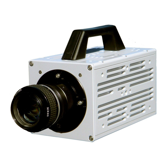
Chapter. 2 Setup 2.2.4. Interchangeable Lens Mounts The lens mount on the system can be changed according to the recording application. There are three types of interchangeable lens mounts, "G type F Mount", "C Mount", "Nikon F Mount", "C Mount", How to change lens mounts (G type F Mount →... -
Page 23: Lcd Remote Controller (Optional)
Keypad signal (Amphenol) (Amphenol) The LCD remote controller is optional. It is not included in the standard configuration. For how to operate of the LCD Remote Controller, refer to "LCD Remote Controller User's Manual". FASTCAM SA3 Hardware Manual... -
Page 24: Serial Control
For details, check the command list. Serial control commands are available as separate list of commands. Please contact Photron or the dealer where the system was purchased regarding the command list. A cable is also not offered as an accessory. When using RS-422 control, construct a cable using the pin diagram below for reference. -
Page 25: I/O Port Connector
Use extreme caution as there is a risk of damage to both devices, the input device and the output device. MCDL I/O PORT (Camera Body) D-sub 9-pin Female PT02A-16-26P (023) For the signal which can be inputted, refer to “3.15. Input/Output Signal Types”, page 38. FASTCAM SA3 Hardware Manual... - Page 26 Chapter. 2 Setup Camera body Cable conector Connector Input Signal Name Conector model No. model No. Name conector (Manufacturer) (Manufacturer) TRIGGER TTL IN TRIGGER TTL OUT TRIGGER SW IN SYNC IN GENERAL IN GENERAL OUT1 GENERAL OUT2 D-sub9 pin MCDL CLK- D-sub9 pin MCDL CLK+ D-sub9 pin...
-
Page 27: Power Supply Connector
Warning power supply you cannot guarantee the safety of. By using a power supply outside of the system specifications, not only is there the danger of the system malfunctioning, but also of fire and electric shock. FASTCAM SA3 Hardware Manual... -
Page 28: Device Connections
Chapter. 2 Setup 2.3. Device Connections 2.3.1. Connecting a Video Monitor A video monitor connected to the camera controller can be used to check the live image (Camera Pass - through image). Connect the video input connector according to the video signal type of the monitor to display to the “VIDEO OUT”... -
Page 29: Connecting The Ac Power Supply
Connect the AC cable to the AC power supply unit. Connect the AC cable to the power outlet. For the specification of the power supply which can be used, refer to “5.1.2. General Specifications”, page 65. FASTCAM SA3 Hardware Manual... -
Page 30: Connecting The Lcd Remote Controller (Optional)
Chapter. 2 Setup 2.3.3. Connecting the LCD Remote Controller (Optional) If you have the optional LCD remote controller, connect it by plugging the LCD remote controller connector into the connector labeled "KEYPAD" on the rear of the camera body. The LCD remote controller is hot-pluggable. It can be plugged in and removed while the system's power is on. -
Page 31: Connecting A Pc
The maximum cable length between the PC and the system is, compliant to the 1000BASE-T specification, up to 100 m. One PC can connect to a maximum of 64 Photron Gigabit Ethernet interface equipped cameras using a hub. When connecting multiple devices, connect through a switching hub that can connect at 1000BASE-T. - Page 32 Chapter. 2 Setup...
-
Page 33: Chapter. 3 Recording
3.20. Event Marker Function 3.21. Using USER SW (Programmable Switch) 3.22. Using MCDL (Multi Channel Data Link) 3.23. IRIG Time Code (External Time Synchronization) 3.24. IRIG-sync Operation 3.25. 8BIT Recording Mode 3.26. Diredt Trigger / Direct Start Mode FASTCAM SA3 Hardware Manual... -
Page 34: Image Initialization (Calibration)
Executing Calibration Calibration is executed from the "LCD remote controller (optional)" or from PFV. For the procedure of performing this function, refer to "LCD Remote Controller User's Manual" or "Photron FASTCAM Viewer User's Manual". 3.1.2. Saving Calibration Settings The black image data for correction use that was obtained by executing the calibration can be saved as one pattern internally on the system. -
Page 35: Selecting The Frame Rate
For more information of relation between Frame Rate and Resolution, refer to “5.1.4. Frame Rate and Resolution”, page 68. FASTCAM SA3 Hardware Manual... -
Page 36: Selecting The Shutter Speed
Chapter. 3 Recording 3.4. Selecting the Shutter Speed With the system, the shutter speed is independent of the frame rate, and you can control the exposure time in one frame using the electric shutter. By making an exposure that is of a shorter period than the frame rate, high-speed objects can be photographed blur-free. -
Page 37: Ds Shutter Function
When using the DS SHUTTER function on a color type, there are situations where the colors become unbalanced and the color reproducibility degrades. The amount of adjustment is expressed as %.For the strength of the adjustment, 0% is no adjustment, 95% is the maximum effect. FASTCAM SA3 Hardware Manual... -
Page 38: Auto Exposure Operation
Chapter. 3 Recording 3.6. AUTO EXPOSURE Operation The system has a function that automatically varies the shutter (the sensor’s exposure time) for the quantity of light input so that it will achieve the desired image output level. After the settings are made once, in a situation where settings cannot be changed, this function displays its effect when recording in an environment where the subject’s amount of light changes. - Page 39 In this case, the variable shutter operation cannot place the image level in the desired ③ position and a phenomenon occurs where the image output level is unstable. When a situation like this occurs, it can be resolved by making RANGE a larger value. FASTCAM SA3 Hardware Manual...
-
Page 40: Selecting The Trigger Mode
Chapter. 3 Recording 3.7. Selecting the Trigger Mode With the system, in order to reliably capture high-speed phenomena, many kinds of trigger modes have been made available. These trigger modes are explained next. There are six types of trigger modes which are listed below. - START - CENTER - END... -
Page 41: End Mode
The number of frames recorded each time the trigger is input can be set as desired, in one frame increments, from one frame to the maximum of all the recordable frames available. FASTCAM SA3 Hardware Manual... -
Page 42: Random Reset Mode
Chapter. 3 Recording 3.7.6. RANDOM RESET Mode RANDOM RESET mode is explained here by comparing its operation with the normal mode. RANDOM RESET mode is a mode to improve the temporal accuracy of the record start timing and the timing of the trigger input, where, to put it simply, with the input of the trigger signal, at the timing that it is input, the camera’s record timing is reset. -
Page 43: Two Stages Mode
[GENERAL IN] connector. There is only one section of high-speed recording within the recording time. GENERAL_IN Input"H" High-speed setting operation from next frame GENERAL_IN Input "L" Low-speed setting operation from next frame (When the polarity is positive) FASTCAM SA3 Hardware Manual... -
Page 44: Low Light Mode
Chapter. 3 Recording 3.8. LOW LIGHT Mode The more you increase the frame rate or shutter speed of the camera, the more the amount of light entering the camera decreases, making the displayed image darker. Low light mode is a function that temporarily increases the exposure time, making the displayed image easier to see to enable you to focus and setup camera. -
Page 45: White Balance Adjustment (Color Types Only)
The values set here are stored in the camera body's internal memory as the user preset, and they can be loaded by selecting USER. There are also two methods for setting user white balance, AUTO USER and EDIT USER. FASTCAM SA3 Hardware Manual... -
Page 46: Color Enhancement Function (Color Types Only)
Chapter. 3 Recording 3.11. Color Enhancement Function (Color Types Only) Color types feature an image color enhancement setting. The image color enhancement level can be adjusted in five steps, including the OFF setting. Menu Display Contents Turns the color enhancement mode off S Sets x0.5 color enhancement x0.5 (LEVEL1) S Sets x1 (default) color enhancement... - Page 47 D1: Gain 1x The input is always linear output. This LUT is used for normal conditions. D3: Gamma 0.6 This LUT is 0.6 gamma correction. D3: Gamma 0.45 This LUT is 0.45 gamma correction. FASTCAM SA3 Hardware Manual...
- Page 48 Chapter. 3 Recording D4: Gain 2x The gain is doubled and you can display the dark areas of the image emphasized. D5: Gain 4x The gain is doubled and you can display the dark areas of the image emphasized. This LUT emphasizes the dark portions even more than D4.
-
Page 49: Using A Custom Lut
3.12.2. Using a Custom LUT Creating a LUT pattern is done with PFV. For the creation method of a LUT pattern, refer to “Photron FASTCAM Viewer User's Manual”. 3.13. Edge Enhancement Function With the system's edge enhancement setting, you can enhance the edges in the recorded image in three steps. -
Page 50: Input/Output Signal Types
Chapter. 3 Recording 3.15. Input/Output Signal Types With the system, many signals can be input and output through the I/O cable. Signals that can be input and output from the I/O cable are listed below. A signal other than the specified signal must not be input to the various connectors. Use extreme caution as there is a risk of damage to both devices, the input device and the output device. -
Page 51: General In Connector
Inputs a change recording ready status signal (READY ON/OFF). To make the setting from the menu, refer to “3.18.1. GENERAL IN Signal Settings” ,page49. To make the setting from PFV, refer to the “Photron FASTCAM Viewer User’s Manual”. 3.15.6. GENERAL OUT (1,2,3) Connector These are also BNC connectors. -
Page 52: Using External Triggers
Chapter. 3 Recording 3.16. Using External Triggers With the system, you can record by receiving various trigger signals matched to the recording application. The trigger signals that can be used on the system are explained here, along with a description of how to use them. 3.16.1. - Page 53 OUT2 390ΩF IN2- 0.1μF SIGNAL_GND GENERAL TTL IN Circuit Diagram IL611-3 390ΩF IN1+ SYNC SYNC_IN IN1- OUT1 IN2+ OUT2 GENERAL_IN IN2- GENERAL 390ΩF 0.1μF SIGNAL_GND TRIG SW IN Circuit Diagram MICROSD150-02 NFW31SP506X1E4 TRIG_SW__IN TRIG_SW 220ΩF 0.1μF FASTCAM SA3 Hardware Manual...
-
Page 54: Outputting External Trigger Signals
Chapter. 3 Recording 3.16.2. Outputting External Trigger Signals With the system, you can externally output trigger signals. Output is performed with the TRIG TTL OUT connector's dedicated trigger output system provided by the system, and additionally, output can also be optionally set from the GENERAL OUT connector. External trigger signal output settings are also made by selecting [SYNC IN/OUT] from the menu and [TRIG TTL] OUT or [GENERAL OUT] from the submenu. -
Page 55: Using External Synchronization Signals
I/O delay amuont Outputs a positive polarity CMOS (74ACT541 buffer) SYNC POS Approx. 160nsec vertical synchronization signal. output, positive polarity Outputs a negative polarity CMOS (74ACT541 buffer) SYNC NEG Approx. 170nsec vertical synchronization signal. output, negative polarity FASTCAM SA3 Hardware Manual... -
Page 56: Synchronizing Multiple Fastcam Sa3 Systems(Multiple Unit Synchronized Recording)
Chapter. 3 Recording 3.17.3. Synchronizing Multiple FASTCAM SA3 Systems(Multiple Unit Synchronized Recording) The system can perform synchronized recording by synchronizing multiple units using external. Synchronization input/output CAMERA No.2 CAMERA No.1 (SLAVE) SYNC IN (MASTER) SYNC OUT (BNC Cable) Synchronized recording settings using the system are made with the "LCD remote controller (optional)"... - Page 57 ENTER key to select. If steps, 2 to 3 are completed when no synchronization signal is being input, the camera will not operate normally. As detailed in the procedure, make the settings when the signal is being input. FASTCAM SA3 Hardware Manual...
-
Page 58: Synchronizing The System With Other External Devices (Frame Rate Synchronized Recording)
Chapter. 3 Recording 3.17.4. Synchronizing the System with Other External Devices (Frame Rate Synchronized Recording) With the system, in addition to the frame rate preset in the system, a function has been provided where you can receive a synchronization signal externally, set the frame rate with that frequency, and record. - Page 59 (an error of about ±1-5Hz is produced). For example, when performing external device synchronization inputting a synchronization signal of 10,000Hz, the monitor display error is: 10,000 Hz ±1Hz = 9,999 fps to 10,001 fps. The specifications of 60K type is 60,000fps FASTCAM SA3 Hardware Manual...
-
Page 60: Synchronizing The System With Other Cameras (Mixed Device Synchronized Recording)
For camera types that can perform synchronized recording or for detailed instructions on making the settings, contact Photron at the contact information in "7.1. Contact Information"... -
Page 61: General Signal Settings
When using the camera as a part of a system, verify the characteristics of the input signals before using them. For the details of an EVENT POS/NEG setup, refer to “3.20. Event Marker Function”, page 52. FASTCAM SA3 Hardware Manual... -
Page 62: General Out Signal Settings
Chapter. 3 Recording 3.18.2. GENERAL OUT Signal Settings Details of the signals output from the GENERAL OUT connector explained in section “3.15. Input/Output Signal Types” are shown in the chart below. There are three GENERAL OUT connectors and individual settings can be made for each connector. Menu Display Contents Signal Type... -
Page 63: Signal Delay
When the frame rate is set to 96,000 fps or higher, x20 and x30 cannot be set. An accurate frequency is output, but when SYNC OUT TIMES is set to a large value with a high frame rate, the setting may result in frequency errors. FASTCAM SA3 Hardware Manual... -
Page 64: Event Marker Function
Chapter. 3 Recording 3.20. Event Marker Function With the system, it is possible to input an external signal during recording, at the instant the frame number is stored, and during playback you can immediately access, or jump to, the stored frame numbers (event markers). -
Page 65: Using User Sw (Programmable Switch)
The same function as the [REC READY] key on the keypad. The same function as the [REC] key on the keypad. LOW LIGHT The same function as the [LOW LIGHT] key on the keypad. CALIBRATE The same function as the [CALIBRATE] key on the keypad. FASTCAM SA3 Hardware Manual... -
Page 66: Using Mcdl (Multi Channel Data Link)
1/10th of the interval of each frame rate. The saved data can be played as a waveform image the “Photron FASTCAM VIEWER” (PFV) software. Additionally, it can easily be played on the VIDEO display. -
Page 67: Irig Time Code (External Time Synchronization)
The system supports IRIG-B input and can add an IRIG code to each recorded frame. The sample timing for the IRIG code is once each frame. The recorded IRIG code is displayed on the VIDEO display or with the “Photron FASTCAM VIEWER” software. -
Page 68: Irig-Sync Operation
EXPOSURE : Exposure to the camera sensor (exposure is indicated by high duration) CAM_V : Camera’s vertical sync signal For the settig about the function, refer to the "Photron FASTCAM Viewer User's Manual" or the "LCD Remote Controller User's Manual". -
Page 69: 8Bit Recording Mode
12bits record. Therefore, more long time data storage becomes possible. 8bit Recording Mode setting can be made with the "LCD remote controller (optional)" or PFV. For the details of a 8 bit Recording Mode setup, refer to「5.1.6. Recordable Image Count/ Resolution(Bit depth)」,Page 72 FASTCAM SA3 Hardware Manual... -
Page 70: Direct Trigger / Direct Start Mode
For details of how to set the camera to DIRECT START Mode, refer to “LCD Remote Controller User’s Manual” or “Photron FASTCAM Viewer User’s Manual”. For details of GENERL IN signal settings, refer to “3.16.1. GENERAL IN Signal Settings”. -
Page 75: Chapter. 5 Product Specifications
Chapter. 5 Product Specifications 5.1. Specifications 5.2. Dimensions FASTCAM SA3 Hardware Manual... -
Page 76: Specifications
Chapter. 5 Product Specifications 5.1. Specifications 5.1.1. Product Specifications 60K type 120K type Image Sensor CMOS image sensor Sensor Resolution (full) 1,024x1,024 pixels Max. Full Frame Rate 1,000 fps (1,024x1,024) 2,000 fps (1,024x1,024) Max. Frame Rate 60,000 fps (128x16) 120,000 fps (128x16) Min. -
Page 77: General Specifications
AC Power Suppy Unit 670 g Photron has verified two types of AC cables, type A (standard for Japan, USA, Canada, etc.) and type SE (standard for Germany, France, etc.). However, when those cables cannot properly receive power when plugged in, use the proper AC cable for the region's standards and verify that AC cable works properly. -
Page 78: Options
Chapter. 5 Product Specifications 5.1.3. Options User Options LCD remote controller I/O Cable F Mount Adapter C Mount Adapter 4 output trigger box Spare power supply connector (for a custom cable) Dust-proof cover for the LAN connector Dedicated carry case Memory backup battery External battery for operation... - Page 79 FASTCAM SA3 Hardware Manual...
-
Page 80: Frame Rate And Resolution
Chapter. 5 Product Specifications 5.1.4. Frame Rate and Resolution FASTCAM SA3 type 60K (1,024×1,024~1,024×16) Image 1,024 1,024 1,024 1,024 1,024 1,024 1,024 1,024 1,024 Size × × × × × × × × × Frame 1,024 Rate ○ ○ ○... - Page 81 FASTCAM SA3 type 60K (768×1,024~768×16) Image Size × × × × × × × × × Frame 1,024 Rate ○ ○ ○ ○ ○ ○ ○ ○ ○ 50(PAL) ○ ○ ○ ○ ○ ○ ○ ○ ○ ○ ○...
- Page 82 Chapter. 5 Product Specifications FASTCAM SA3 type 60K (512×1,024~512×16) Image Size × × × × × × × × Frame 1,024 Rate ○ ○ ○ ○ ○ ○ ○ ○ 50(PAL) ○ ○ ○ ○ ○ ○ ○ ○ ○...
- Page 83 FASTCAM SA3 type 60K (256×1,024~256×16) Image Size × × × × × × × × Frame 1,024 Rate ○ ○ ○ ○ ○ ○ ○ ○ 50(PAL) ○ ○ ○ ○ ○ ○ ○ ○ ○ ○ ○ ○ ○...
- Page 84 Chapter. 5 Product Specifications FASTCAM SA3 type 60K (128×1,024~128×16) Image Size × × × × × × × × Frame 1,024 Rate ○ ○ ○ ○ ○ ○ ○ ○ 50(PAL) ○ ○ ○ ○ ○ ○ ○ ○ ○...
- Page 85 FASTCAM SA3 Hardware Manual...
- Page 86 Chapter. 5 Product Specifications FASTCAM SA3 type 120K (1,024×1,024~1,024×16) Image 1,024 1,024 1,024 1,024 1,024 1,024 1,024 1,024 1,024 Size × × × × × × × × × Frame 1,024 Rate ○ ○ ○ ○ ○ ○ ○ ○...
- Page 87 FASTCAM SA3 type 120K (768×1,024~640×640) Image Size × × × × × × × × × Frame 1,024 Rate ○ ○ ○ ○ ○ ○ ○ ○ ○ 50(PAL) ○ ○ ○ ○ ○ ○ ○ ○ ○ ○ ○...
- Page 88 Chapter. 5 Product Specifications FASTCAM SA3 type 120K (512×1,024~512×16) Image Size × × × × × × × × Frame 1,024 Rate ○ ○ ○ ○ ○ ○ ○ ○ 50(PAL) ○ ○ ○ ○ ○ ○ ○ ○ ○...
- Page 89 FASTCAM SA3 type 120K (256×1,024~256×16) Image Size × × × × × × × × Frame 1,024 Rate ○ ○ ○ ○ ○ ○ ○ ○ 50(PAL) ○ ○ ○ ○ ○ ○ ○ ○ ○ ○ ○ ○ ○...
- Page 90 Chapter. 5 Product Specifications FASTCAM SA3 type 120K (128×1,024~128×16) Image Size × × × × × × × × Frame 1,024 Rate ○ ○ ○ ○ ○ ○ ○ ○ 50(PAL) ○ ○ ○ ○ ○ ○ ○ ○ ○...
-
Page 91: Recordable Image Count/Resolution
5.1.5. Recordable Image Count/Resolution FASTCAM SA3 type 60K Memory 2 GB Type Memory 4 GB Type Memory 8 GB Type Resolution Frame Rate Rec. Time Rec. Frames Rec. Time Rec. Frames Rec. Time Rec. Frames (seconds) (count) (seconds) (count) (seconds) (count) 1,024×1,024... -
Page 92: Recordable Image Count/ Resolution (Bit Depth)
Chapter. 5 Product Specifications 5.1.6. Recordable Image Count/ Resolution (Bit depth) FASTCAM SA3 type 60K / 120K Memory 2 GB Type Memory 4 GB Type Memory 8 GB Type Resolution 8 bit 12 bit 8 bit 12 bit 8 bit... -
Page 93: Shutter Speed List
1/ 50,000 1/ 60,000 1/ 75,000 1/ 100,000 1/ 120,000 1/ 200,000 1/ 240,000 1/ 300,000 1/ 400,000 1/ 500,000 * For frame rates 2,000 fps or lower, you can set each as far as "1/frame". FASTCAM SA3 Hardware Manual... -
Page 94: Dimensions
Chapter. 5 Product Specifications 5.2. Dimensions 5.2.1. Camera Body All dimensions are in millimeters (mm) – 25.4 mm equals one inch. These diagrams are not shown to scale. 261.07 253.47 37.67 65.62 6-M5 DEPTH 6 126.97 2-Φ5 DEPTH 140.97 145.62 1/4-20UNC DEPTH 6 154.97 225.62... -
Page 95: Ac Power Supply Unit
(mm) 261.07 253.47 246.1 190.7 140.6 37.67 65.62 2-Φ5 DEPTH 6-M5 DEPTH 6 126.97 140.97 1/4-20UNC DEPTH 6 145.62 154.97 225.62 225.62 154.97 145.62 140.97 126.97 65.62 6-M5 DEPTH 6 1/4-20UNC DEPTH 6 2-φ5 DEPTH 6 FASTCAM SA3 Hardware Manual... - Page 96 Chapter. 5 Product Specifications 5.2.4. AC Power Supply Unit All dimensions are in millimeters (mm) – 25.4 mm equals one inch. These diagrams are not shown to scale. 3000...
-
Page 97: Chapter. 6 Warranty
Chapter. 6 Warranty 6.1. About the Warranty FASTCAM SA3 Hardware Manual... -
Page 98: About The Warranty
Consumable goods (cables) When repair, adjustment, or alternation done by an entity other than Photron service has been performed on the system, or damage or malfunction that is determined to be attributed to a fault in the use the product. -
Page 99: Chapter. 7 Contacting Photron
Chapter. 7 Contacting Photron 7.1. Contact Information FASTCAM SA3 Hardware Manual... -
Page 100: Contact Information
Chapter. 7 Contacting Photron 7.1. Contact Information For inquires related to PFV, contact Photron at the contact information listed below. Additionally, the following items will be verified when inquiring, so please prepare them in advance. Items Verified Concrete Example Company, school or organization name,... - Page 101 Hardware Manual Revision 1.06E Publication Date June, 2013 Publisher PHOTRON LIMITED Chiyoda Fujimi Bldg., Fujimi 1-1-8, Chiyoda-ku, Tokyo 102-0071 © 2013.PHO T RON LIMIT ED, All rights reserved. Printed i n Japa n. (Control No. E1306013518U)
Need help?
Do you have a question about the FASTCAM SA3 and is the answer not in the manual?
Questions and answers