Table of Contents
Advertisement
Quick Links
Advertisement
Table of Contents

Related Manuals for Photron FASTCAM SA8


Summary of Contents for Photron FASTCAM SA8
- Page 2 The copyright of this manual is held by PHOTRON LIMITED. Product specifications and manual contents are subject to change without notice. PHOTRON LIMITED bears no responsibility for any results by using our products nor by applying this manual to any operations.
- Page 3 Introduction Thank you for your purchase of Photron’s high-speed camera system, the “FASTCAM SA8” (referred to below as the system). This manual contains the operating instructions and warnings necessary for using the system. Before using the system, please read the entire manual. If any part of this manual is unclear, contact Photron using the contact information printed at the back of the manual.
- Page 4 This chapter explains operations related to recording. Chapter. 4 Connecting a PC This chapter explains the procedure for connecting the system to a PC. Refer to the “Photron FASTCAM Viewer User’s Manual” for additional details on using a PC to control the system.
- Page 5 In order to prevent injury to yourself and others, and to prevent damage to property, carefully observe the following safety precautions. Photron has given its full attention to the safety of this system. However, the extent of damage and injury potentially caused by ignoring the content of the safety precautions and using the system incorrectly is explained next.
- Page 6 ■ Do not plug in or unplug the power cord with wet hands. Doing so can cause electric shock. ■ This chapter lists the contact information to use when contacting Photron if the system malfunctions or if a portion of the manual is unclear.
- Page 7 Warning ■Do not use the accessories by the usage that a manufacturer does not specify. It may cause damage of protection. ■ When throwing away this product, it can’t throw away as waste. Please contact PHOTRON EUROPE LIMITED.
- Page 8 Caution ■ Always unplug the system when cleaning it or when it is unused for a long period of time. Leaving or storing the system connected to the power source might cause fire from insulation deterioration or electrical discharge. ■Please consult us in advance when you perform an event by which laser light or direct rays fall on the image sensor surface.
- Page 9 For more information about the recycling of this product, please contact your local city office, waste authority, approved scheme or your household waste disposal service or visit www.photron.com. (EEA: Norway, Iceland and Liechtenstein) This product is in conformity with the protection requirements of EU Council Directive 2014/30/EU (Class A) on the approximation of the laws of the Member States relating to electromagnetic compatibility.
- Page 10 Cleaning of the Image Sensor Surface Electrostatic Discharge (ESD) events may cause immediate and unrecoverable damage to the image sensor. Please read the following instructions and take EXTREME CARE when cleaning the image sensor surface. ■ ALWAYS take appropriate anti-static precautions when cleaning or working near the Image sensor.
-
Page 12: Table Of Contents
Table of Contents Chapter. 1 Overview 1.1. Product Overview and Features ................2 Chapter. 2 Setup 2.1. System Components and Accessories ..............4 2.1.1. Components ....................4 2.1.2. Accessories/Options ................... 4 2.1.3. Type ......................5 2.2. Part Names ......................6 2.2.1. - Page 13 3.12. Using External Synchronization Signals ..............35 3.12.1. Inputting an External Synchronization Signal ........... 35 3.12.2. Outputting an External Synchronization Signal ........35 3.12.3. Synchronizing Multiple FASTCAM SA8 Systems (Multiple Unit Synchronized Recording) ........... 36 3.12.4. Synchronizing the System with Other Cameras (Mixed Device Synchronized Recording) ..........
- Page 14 Camera Body(C Mount) ................65 5.2.3. AC / DC Adaptor ..................66 5.2.4. Memory Backup Buttery ................66 5.2.5. Remote Keypad (Option) ................67 Chapter. 6 Warranty 6.1. About the Warranty ....................70 Chapter. 7 Contacting Photron 7.1. Contact Information....................72...
-
Page 15: Chapter. 1 Overview
Chapter. 1 Overview 1.1. Product Overview and Features FASTCAM SA8 Hardware Manual... -
Page 16: Product Overview And Features
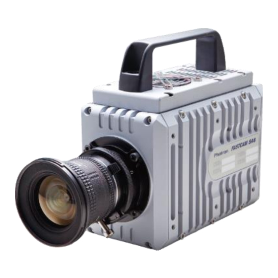
1.1. Product Overview and Features The FASTCAM SA8 is a powerful engineering tool for use in research and development, design, production, and quality control, and in numerous fields such as science, medicine, biology, aviation and space. -The system features superior basic performance with megapixel resolution, an... -
Page 17: Chapter. 2 Setup
Chapter. 2 Setup 2.1. System Components and Accessories 2.2. Part Names 2.3. Device Connections FASTCAM SA8 Hardware Manual... -
Page 18: System Components And Accessories
Chapter. 2 Setup 2.1. System Components and Accessories 2.1.1. Components Refer to the attached packing list for this product's standard components and accessories. 2.1.2. Accessories/Options The following options are available for the system. Remote Keypad 4 Output Trigger Box Specialized Spare Power Supply Connector (For Creating a Custom Cable) Specialized Dust-Proof Cover for the LAN Connector Specialized Carrying Case Specialized Memory Backup Battery... -
Page 19: Type
There are a total of 8 types according to the combination of options. The types are listed below. Full Frame Max. Frame Rate Sensor Type Memory Type Name Max Frame Rate FASTCAM SA8 type 30K-C1 Color FASTCAM SA8 type 30K-C2 30,000fps 3,500fps FASTCAM SA8 type 30K-M1 Monochrome FASTCAM SA8 type 30K-M2... -
Page 20: Part Names
Part Names The system is composed of components including the camera body, AC / DC Adaptor, and the "Photron FASTCAM Viewer" control software (referred to below as PFV). For each of the system components. - Do not expose to shock outside of specifications. -
Page 21: Camera Body Part Names
Power Supply Switch Backup Battely LEDs USER Programmable Switch KEYPAD Remote Keypad Connector GIGABIT EHTER Gigabit Ethernet LAN Cable Connector DC22-32V 65VA Power Supply Connector VIDEO OUT Video Output Connector Rear I/O PORT I/O Port Connector FASTCAM SA8 Hardware Manual... -
Page 22: Status Display Leds On The Rear Of The Camera Body
Chapter. 2 Setup 2.2.3. Status Display LEDs on the Rear of the Camera Body There are a number of LEDs on the rear of the system's camera body. These LEDs indicate the status of the system. The meaning of each LED is explained here. Status Display LEDs ... - Page 23 Be sure to check the status with LEDs or video monitor in using camera with backup battery. If thermal protection works or abnormal status is indicated, power off the camera and remove the cause or contact Photron. Video monitor in case of failure BATTERY ERROR FASTCAM SA8 Hardware Manual...
-
Page 24: Interchangeable Lens Mounts
Chapter. 2 Setup 2.2.4. Interchangeable Lens Mounts The lens mount on the system can be changed according to the recording application. There are three types of interchangeable lens mounts, "G type F Mount", "C Mount", and Lens mount with filter changer. How to change lens mounts (G type F Mount →... -
Page 25: Remote Controller (Optional)
G52L0C-P10QJ00-0000 S22L0C-P10MJG0-820S KEYPAD Keypad signal (ODU) (ODU) The remote controller is optional. It is not included in the standard configuration. For how to operate of the Remote Controller, refer to "Remote Controller User's Manual". FASTCAM SA8 Hardware Manual... -
Page 26: Rs-422 Serial Control
For details, check the command list. Serial control commands are available as separate list of commands. Please contact Photron or the dealer where the system was purchased regarding the command list. A cable is also not offered as an accessory. When using RS-422 control, construct a cable using the pin diagram below for reference. -
Page 27: I/O Port Connector
Use extreme caution as there is a risk of damage to both devices, the input device and the output device. I/O PORT (Camera Body) ECJ.2B.326.CLD(LEMO) For the signal which can be inputted, refer to “3.10. Input / Output Signal Types”, page 30. FASTCAM SA8 Hardware Manual... - Page 28 Chapter. 2 Setup Camera body Cable connector Connector Input Signal Name Connector type No. type No. Name connector (Manufacturer) (Manufacturer) GENERAL OUT2 RESERVE RESERVE RESERVE RESERVE RESERVE RESERVE IRIG GND IRIG SYNC IN TRIG TTL IN TRIG TTL OUT ECJ.2B.326.CLD FGJ.2B.326.CLLD92Z I/O PORT (LEMO)
-
Page 29: Power Supply Connector
Please use a external power supply with the suitable rating which was estimated by Warning IEC/EN 61010-1 3 Edition (compiled with CI. 6.3 and CI. 2.5), and separated from the main circuit by double insulation or reinforced insulation FASTCAM SA8 Hardware Manual... -
Page 30: Device Connections
Chapter. 2 Setup 2.3. Device Connections 2.3.1. Connecting a Video Monitor A video monitor connected to the camera controller can be used to check the live image (Camera Pass - through image). Connect the video input connector according to the video signal type of the monitor to display to the “VIDEO OUT”... -
Page 31: Connecting The Power Supply
Connect the AC cable to the AC / DC Adaptor. Connect the AC cable to the power outlet. Turn on the Power SW one the system For the specification of the power supply which can be used, refer to “5.1.2. General Specifications”, page 53. FASTCAM SA8 Hardware Manual... -
Page 32: Connecting The Keypad (Optional)
Chapter. 2 Setup 2.3.3. Connecting the Keypad (Optional) If you have the optional Keypad, connect it by plugging the Keypad connector into the connector labeled "KEYPAD" on the rear of the camera body. The Keypad is hot-pluggable. It can be plugged in and removed while the system's power is on. ... -
Page 33: Connecting A Pc
The maximum cable length between the PC and the system is 100 m (compliant to the 1000BASE-T specification). One PC can connect to a maximum of 64 Photron Gigabit Ethernet interface equipped cameras using a hub. When connecting multiple devices, connect through a switching hub that can connect at 1000BASE-T. -
Page 34: Memory Backup Battery (Option)
Chapter. 2 Setup 2.3.6. Memory Backup Battery (Option) As an optional accessory, a battery set for conserving video information in the camera memorys is avalible. In case of an outer power-fail, it can maintain the content of the memory for about 30 minutes in maximum. -
Page 35: Chapter. 3 Recording
3.10. Input / Output Signal Types 3.11. Using External Triggers 3.12. Using External Synchronization Signals 3.13. GENERAL Signal Settings 3.14. Signal Delay 3.15. Using USER SW (Programmable Switch) 3.16. IRIG Time Code (External Time Synchronization) 3.18. 8bit Recording Mode FASTCAM SA8 Hardware Manual... -
Page 36: Selecting The Frame Rate
Chapter. 3 Recording 3.1. Selecting the Frame Rate With the system, you can record images from 60 to 3,500 fps (or 2,000 fps at 15Ktype) using the full 1,280x1,024 pixel resolution of the image sensor. For frame rates faster than 2,000 fps, high-speed photography is achieved by limiting the read area of the image sensor. -
Page 37: Selecting The Trigger Mode
For example, in a situation with a maximum useable memory for two seconds of recording, one second before and one second after the trigger was input is recorded for a total of two seconds of high-speed video. FASTCAM SA8 Hardware Manual... -
Page 38: End Mode
Chapter. 3 Recording 3.4.3. END Mode END mode is a trigger mode where the content recorded immediately before the trigger is input is saved to memory. This mode is suitable for recording a high-speed phenomenon where it is hard to predict when the important action will start and stop. -
Page 39: Low Light Mode
The values set here are stored in the camera body's internal memory as the user preset, and they can be loaded by selecting USER. There are also two methods for setting user white balance, AUTO USER and EDIT USER. FASTCAM SA8 Hardware Manual... -
Page 40: Color Enhancement Function (Color Types Only)
Chapter. 3 Recording 3.7. Color Enhancement Function (Color Types Only) Color types feature an image color enhancement setting. The image color enhancement level can be adjusted in five steps, including the OFF setting. Display Contents Turns the color enhancement mode off x0.5 (LEVEL1) S Sets x0.5 color enhancement x1... - Page 41 DEF1: Gain 1x The input is always linear output. DEF2: Gamma 0.8 This LUT is 0.8 gamma correction. This LUT is used for normal conditions. DEF3: Gamma 0.6 This LUT is 0.6 gamma correction. FASTCAM SA8 Hardware Manual...
- Page 42 Chapter. 3 Recording DEF4: Gain 2x The gain is doubled and you can display the dark areas of the image emphasized. DEF5: Gain 4x The gain is quadrupled and you can display the dark areas of the image emphasized. This LUT emphasizes the dark portions even more than D4.
-
Page 43: Using A Custom Lut
3.8.2. Using a Custom LUT Creating a LUT pattern is done with PFV. For the creation method of a LUT pattern, refer to “Photron FASTCAM Viewer User's Manual”. 3.9. Edge Enhancement Function With the system's edge enhancement setting, you can enhance the edges in the recorded image in three steps. -
Page 44: Input / Output Signal Types
Chapter. 3 Recording 3.10. Input / Output Signal Types With the system, many signals can be input and output through the I/O cable. Signals that can be input and output from the I/O cable are listed below. A signal other than the specified signal must not be input to the various connectors. Use extreme caution as there is a risk of damage to both the input device and the output device. -
Page 45: General In Connector
READY POS/NEG Inputs a change recording ready status signal (READY ON/OFF). To make the setting from PFV, refer to the “Photron FASTCAM Viewer User’s Manual”. 3.10.6. GENERAL OUT (1, 2) Connector These are also BNC connectors. The signals below can be changed and output from the PFV. -
Page 46: Using External Triggers
Chapter. 3 Recording 3.11. Using External Triggers With the system, you can record by receiving various trigger signals matched to the recording application. The trigger signals that can be used on the system are explained here, along with a description of how to use them. 3.11.1. - Page 47 TRIG TTL IN / GENERAL TTL IN / TRIG SW IN Circuit Diagram FASTCAM SA8 Hardware Manual...
-
Page 48: Outputting External Trigger Signals
Chapter. 3 Recording 3.11.2. Outputting External Trigger Signals With the system, you can externally output trigger signals. Output is performed with the TRIG TTL OUT connector's dedicated trigger output system provided by the system, and additionally, output can also be optionally set from the GENERAL OUT connector. You can change External trigger signal output settings by PFV. -
Page 49: Using External Synchronization Signals
Delay Time Outputs a positive polarity CMOS (74ACT541 buffer) SYNC POS Approx. 253nsec vertical synchronization signal. output, positive polarity Outputs a negative polarity CMOS (74ACT541 buffer) SYNC NEG Approx. 288nsec vertical synchronization signal. output, negative polarity FASTCAM SA8 Hardware Manual... -
Page 50: Synchronizing Multiple Fastcam Sa8 Systems(Multiple Unit Synchronized Recording)
Chapter. 3 Recording 3.12.3. Synchronizing Multiple FASTCAM SA8 Systems(Multiple Unit Synchronized Recording) The system can perform synchronized recording by synchronizing multiple units using external. Synchronization input/output CAMERA No.2 CAMERA No.1 (SLAVE) SYNC IN (MASTER) SYNC OUT (BNC Cable) Synchronized recording settings using the system are made with PFV. The conceptual settings when performing synchronized recording using two systems are explained here. - Page 51 ENTER key to select. If steps, 2 to 3 are completed when no synchronization signal is being input, the camera will not operate normally. As detailed in the procedure, make the settings when the signal is being input. FASTCAM SA8 Hardware Manual...
-
Page 52: Synchronizing The System With Other Cameras (Mixed Device Synchronized Recording)
For camera types that can perform synchronized recording or for detailed instructions on making the settings, contact Photron at the contact information in "7.1. Contact Information"... -
Page 53: General Signal Settings
FET Input 0V - +12V (L level +1.0 or less, H level +2.8V to +12V), Negative Polarity When using the camera as a part of a system, verify the characteristics of the input signals before using them. FASTCAM SA8 Hardware Manual... -
Page 54: General Out Signal Settings
Chapter. 3 Recording 3.13.2. GENERAL OUT Signal Settings Details of the signals output from the GENERAL OUT connector explained in section “3.10. Input / Output Signal Types” are shown in the chart below. There are three GENERAL OUT connectors and individual settings can be made for each connector. -
Page 55: Signal Delay
1000 fps Synchronization Signal SYNC OUT Output An accurate frequency is output, but when SYNC OUT TIMES is set to a large value with a high frame rate, the setting may result in frequency errors. FASTCAM SA8 Hardware Manual... -
Page 56: Using User Sw (Programmable Switch)
Chapter. 3 Recording 3.15. Using USER SW (Programmable Switch) There is a switch that can be set on the back of the system. A setting for the switch is made from the PFV and it can be assigned a different function. As an example, setting the “USER SW” switch on the back of the camera body is explained here. -
Page 57: Irig Time Code (External Time Synchronization)
The system supports IRIG-B input and can add an IRIG code to each recorded frame. The sample timing for the IRIG code is once each frame. The recorded IRIG code is displayed on the VIDEO display or with the “Photron FASTCAM VIEWER” software. -
Page 58: Irig-Sync Operation
EXPOSURE : Exposure to the camera sensor (exposure is indicated by high duration) CAM_V : Camera’s vertical sync signal For the settig about the function, refer to the "Photron FASTCAM Viewer User's Manual" or the "LCD Remote Controller User's Manual". -
Page 59: 8Bit Recording Mode
Therefore, it is possible to record for a longer amount of time. 8bit Recording Mode setting can be made with the “Remote controller (optional)" or PFV. For the details of a 8 bit Recording Mode setup, refer to「5.1.7. Recordable Image Count/Resolution(8bit)」,Page 61. FASTCAM SA8 Hardware Manual... - Page 60 Chapter. 3 Recording...
-
Page 61: Chapter. 4 Connecting A Pc
Chapter. 4 Connecting a PC 4.1. Connecting the Gigabit Ethernet Interface to a PC FASTCAM SA8 Hardware Manual... -
Page 62: Connecting The Gigabit Ethernet Interface To A Pc
The maximum cable length between the PC and the system is, compliant to the 1000BASE-T specification, up to 100 m. One PC can connect to a maximum of 64 Photron Gigabit Ethernet interface equipped cameras using a hub. When connecting multiple devices, connect through a switching hub that can connect at 1000BASE-T. -
Page 63: Connecting The System And A Pc
IP addresses that are already in use on the network. For the procedure for setting the IP address of the system, refer to the "Photron FASTCAM Viewer User's Manual". -
Page 64: Connecting Multiple Systems And A Pc
Connecting Multiple Systems and a PC With PFV, the system’s control software, one PC can connect to and control multiple FASTCAM SA5,FASTCAM SA4 ,FASTCAM 2 ,FASTCAM 1.1, FASTCAM SA7,FASTCAM SA8, FASTCAM APX-RS, and FASTCAM MH4-10K systems. When connecting to multiple systems, set the IP address of each one to a unique setting. -
Page 65: Chapter. 5 Product Specifications
Chapter. 5 Product Specifications 5.1. Specifications 5.2. Dimensions FASTCAM SA8 Hardware Manual... -
Page 66: Specifications
Chapter. 5 Product Specifications 5.1. Specifications 5.1.1. Product Specifications 30K type 15K type Image Sensor CMOS image sensor Sensor Resolution (full) 1,280x1,024 pixels Max. Full Frame Rate 3,500 fps (1,280x1,024) 2,000 fps (1,280x1,024) Max. Frame Rate 30,000 fps (320x256) 15,000 fps (320x256) Min. -
Page 67: General Specifications
Camera + Memory Battery 4.7kg Photron has verified two types of AC cables, type A (standard for Japan, USA, Canada, etc.) and type SE (standard for Germany, France, etc.). However, when those cables cannot properly receive power when plugged in, use the proper AC cable for the region's standards and verify that AC cable works properly. -
Page 68: Options
Chapter. 5 Product Specifications 5.1.4. Options User Options Remote Keypad 4 output trigger box Specialized Spare power supply connector (for a custom cable) Specialized Dust-proof cover for the LAN connector Specialized Dedicated carry case Specialized Memory backup battery... - Page 69 FASTCAM SA8 Hardware Manual...
-
Page 70: Frame Rate And Resolution
Chapter. 5 Product Specifications 5.1.5. Frame Rate and Resolution FASTCAM SA8 type 30K (1,280 x 1,024 to 1,024 x 768) Image 1,280 1,280 1,280 1,280 1,280 1,280 1,280 1,024 1,024 Size × × × × × × × × ×... - Page 71 FASTCAM SA8 type 30K (960 x 720 to 320 x 256) Image Size × × × × × × × × × frame rate(fps) ○ ○ ○ ○ ○ ○ ○ ○ ○ 50(PAL) ○ ○ ○ ○ ○ ○...
- Page 72 Chapter. 5 Product Specifications FASTCAM SA8 type 15K (1,280 x 1,024 to 1,024 x 768) Image 1,280 1,280 1,280 1,280 1,280 1,280 1,280 1,024 1,024 Size × × × × × × × × × frame 1,024 1,024 rate(fps) ○...
- Page 73 FASTCAM SA8 type 15K (960 x 720 to 320 x 256) Image Size × × × × × × × × × frame rate(fps) ○ ○ ○ ○ ○ ○ ○ ○ ○ 50(PAL) ○ ○ ○ ○ ○ ○...
-
Page 74: Recordable Image Count/Resolution(12Bit)
Chapter. 5 Product Specifications 5.1.6. Recordable Image Count/Resolution(12bit) FASTCAM SA8 type 30K Memory 4GB type Memory 8GB type Resolution FrameRate Rec time Rec frames Rec time Rec frames (second) (frame) (second) (frame) 1,280×1,024 3,500 fps 0.622 2,180 1.247 4,365 1,280×768 4,000 fps 0.726... -
Page 75: Recordable Image Count/Resolution(8Bit)
5.1.7. Recordable Image Count/Resolution(8bit) FASTCAM SA8 type 30K Memory 4GB type Memory 8GB type Resolution FrameRate Rec time Rec frames Rec time Rec frames (second) (frame) (second) (frame) 1,280×1,024 3,500 fps 0.934 3,272 1.871 6,549 1,280×768 4,000 fps 1.090 4,363 2.183... -
Page 76: Shutter Speed List
Chapter. 5 Product Specifications 5.1.8. Shutter Speed List Setting Value 1/ 125 1/ 250 1/ 500 1/ 1,000 1/ 1,600 1/ 2,000 1/ 2,500 1/ 2,857 1/ 3,000 1/ 3,333 1/ 4,000 1/ 5,000 1/ 5,556 1/ 6,000 1/ 6,250 1/ 7,000 1/ 7,143 1/ 8,000... - Page 77 FASTCAM SA8 Hardware Manual...
-
Page 78: Dimensions
Chapter. 5 Product Specifications 5.2. Dimensions 5.2.1. Camera Body(G type F Mount) All dimensions are in millimeters (mm) – 25.4 mm equals one inch. These diagrams are not shown to scale. 40.2 195.2 AST C A M IP ADDRESS 1 IP ADDRESS 2 192.168.000.010 192.168.001.010... -
Page 79: Camera Body(C Mount)
12.4 195.2 A ST C A M IP ADDRESS 1 IP ADDRESS 2 192.168.000.010 192.168.001.010 NETWORK MASK 1 NETWORK MASK 2 255.255.255.000 255.255.255.000 Front Side 3/8-19UNC 1/4-20UNC Φ4.7 4-M5 15 14 75.3 29.6 132.7 Botton FASTCAM SA8 Hardware Manual... -
Page 80: Ac / Dc Adaptor
Chapter. 5 Product Specifications 5.2.3. AC / DC Adaptor All dimensions are in millimeters (mm) – 25.4 mm equals one inch. These diagrams are not shown to scale. 1219±50 LED INDICATOR 207.6 AC INPUT, IEC 320/C14 INLET(Class Ⅰ) 190.2 58.8 RUBBER FOOT 5.2.4. -
Page 81: Remote Keypad (Option)
5.2.5. Remote Keypad (Option) (mm) 105.4 28.2 FASTCAM SA8 Hardware Manual... - Page 82 Chapter. 5 Product Specifications...
-
Page 83: Chapter. 6 Warranty
Chapter. 6 Warranty 6.1. About the Warranty FASTCAM SA8 Hardware Manual... -
Page 84: About The Warranty
Consumable goods (cables) When repair, adjustment, or alternation done by an entity other than Photron service has been performed on the system, or damage or malfunction that is determined to be attributed to a fault in the use the product. -
Page 85: Chapter. 7 Contacting Photron
Chapter. 7 Contacting Photron 7.1. Contact Information FASTCAM SA8 Hardware Manual... -
Page 86: Contact Information
Chapter. 7 Contacting Photron 7.1. Contact Information For inquires related to PFV, contact Photron at the contact information listed below. Additionally, the following items will be verified when inquiring, so please prepare them in advance. Items Verified Concrete Example Company, school or organization name,... - Page 87 Publication Date April, 2018 Publisher PHOTRON LIMITED 21F, Jimbocho Mitsui Bldg., 1-105 Kanda Jimbocho, Chiyoda-Ku, Tokyo 101-0051 © 201 6.P H O TR ON LI MI TE D , Al l r ights res er ved . P rin ted in Ja pan.
Need help?
Do you have a question about the FASTCAM SA8 and is the answer not in the manual?
Questions and answers