
Subscribe to Our Youtube Channel
Related Manuals for Photron FASTCAM SA5


Summary of Contents for Photron FASTCAM SA5
- Page 2 This manual was created taking every possible measure to ensure the accuracy of its contents. However, if you find a section which is unclear, a mistake, or an omission, please contact Photron LIMITED using the contact information provided at the end of the manual. Photron LIMITED bears no responsibility for the results of using the product or from following the instructions in this manual.
- Page 3 This manual contains the operating instructions and warnings necessary for using the system. Before using the system, please read the entire manual. If any part of this manual is unclear, contact Photron using the contact information printed at the back of the manual.
- Page 4 This chapter explains operations related to recording. Chapter. 4 Connecting a PC This chapter explains the procedure for connecting the system to a PC. Refer to the “Photron FASTCAM Viewer User’s Manual” for additional details on using a PC to control the system.
- Page 5 In order to prevent injury to yourself and others, and to prevent damage to property, carefully observe the following safety precautions. Photron has given its full attention to the safety of this system. However, the extent of damage and injury potentially caused by ignoring the content of the safety precautions and using the system incorrectly is explained next.
- Page 6 ■ Do not plug in or unplug the power cord with wet hands. Doing so can cause electric shock. ■ This chapter lists the contact information to use when contacting Photron if the system malfunctions or if a portion of the manual is unclear.
- Page 7 Caution ■ Always unplug the system when cleaning it or when it is unused for a long period of time. Leaving or storing the system connected to the power source might cause fire from insulation deterioration or electrical discharge. ■ Do not set the system in a location where the temperature gets unusually hot. The trunk and inside of a car can get especially hot in summer.
- Page 8 Cleaning of the Image Sensor Surface Electrostatic Discharge (ESD) events may cause immediate and unrecoverable damage to the image sensor. Please read the following instructions and take EXTREME CARE when cleaning the image sensor surface. ■ ALWAYS take appropriate anti-static precautions when cleaning or working near the Image sensor.
-
Page 9: Table Of Contents
Table of Contents Chapter. 1 Overview 1.1. Product Overview and Features ................2 Chapter. 2 Setup 2.1. About the System’s Components and Accessories ..........4 2.1.1. Components ....................4 2.1.2. Accessories/Options ................... 4 2.1.3. Model ......................5 2.2. Part Names ......................6 2.2.1. - Page 10 3.15.1. Inputting an External Synchronization Signal ........... 46 3.15.2. Outputting an External Synchronization Signal ........46 3.15.3. Synchronizing Multiple FASTCAM SA5 Systems ........47 (Multiple Unit Synchronized Recording) ..............47 3.15.4. Synchronizing the System with Other External Devices ......49 (Frame Rate Synchronized Recording) ..............
- Page 11 Camera Body .................... 83 5.2.2. LCD Remote Controller (Optional) ............85 5.2.3. AC Power Supply Unit ................88 5.3. Cleaning the Filter ....................89 Chapter. 6 Warranty 6.1. About the Warranty ....................92 Chapter. 7 Contacting Photron 7.1. Contact Information ....................94...
-
Page 13: Chapter. 1 Overview
Chapter. 1 Overview 1.1.Product Overview and Features FASTCAM SA5 / SA5 RV Hardware Manual... -
Page 14: Product Overview And Features
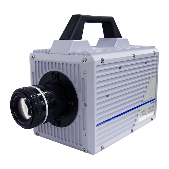
1.1. Product Overview and Features The FASTCAM SA5 / SA5 RV is a powerful engineering tool for use in research and development, design, production, and quality control, and in numerous fields such as science, medicine, biology, aviation and space. The system features superior basic performance with mega pixel resolution, an ultra-sensitive image sensor capable of clear recording in low-light, and an ultra-high speed frame, rate of a maximum of 775,000 fps (frame per second). -
Page 15: Chapter. 2 Setup
Chapter. 2 Setup 2.1. About the System’s Components and Accessories 2.2. Part Names 2.3. Device Connections FASTCAM SA5 / SA5 RV Hardware Manual... -
Page 16: About The System's Components And Accessories
Lens Mount Cap (built into the camera body) I/O (Input and Output) Cable FASTCAM Series Setup Disk (Driver/Application CD) FASTCAM SA5 / SA5 RV Hardware Manual (this manual) Photron FASTCAM Viewer (PFV) User's Manual 10. How to Make a Gigabit Ethernet Connection (Simple Procedure Manual) 11. -
Page 17: Model
FASTCAM SA5 775K-M1 Monochrome 16GB FASTCAM SA5 775K-M2 32GB FASTCAM SA5 775K-M3 "RV (Range Version) type” is prepared for each model. It has be sealed-up a camera chassis for keep it free of dust. FASTCAM SA5 / SA5 RV Hardware Manual... -
Page 18: Part Names
2.2.1. Camera Body For the FASTCAM SA5 system, there are monochrome and a color version, and for each of these versions, there are 8 GB standard memory capacity type and 16 GB (or 32GB) high capacity type. When purchasing, it is possible to select from these models according to the application or your demands. - Page 19 Apperance Rear FASTCAM SA5 RV FASTCAM SA5 / SA5 RV Hardware Manual...
-
Page 20: Camera Body Part Names
Chapter. 2 Setup 2.2.2. Camera Body Part Names Handle FASTCAM SA5 F Mount Front Front Handle Duct (filter) Status Indicator LEDs POWER SW Power Switch USER SW SYNC SYNC POWER TRIGGER IRIG LINK/TRANS MODE READY Programmable Switch GIGABIT ETHER Gigabit Ethernet... - Page 21 I/O PORT I/O Port Connector DC 20 -3 6V 1 30 VA H D SD I H D SD I K EY PA D KEYPAD HD SDI KEYPAD Connector Back HD SDI Output Connector FASTCAM SA5 / SA5 RV Hardware Manual...
-
Page 22: Status Display Leds On The Rear Of The Camera Body
Chapter. 2 Setup 2.2.3. Status Display LEDs on the Rear of the Camera Body There are a number of LEDs on the rear of the system's camera body. These LEDs indicate the status of the system. The function of each LED is explained here. POWER (Green) ... -
Page 23: Interchangeable Lens Mounts
Install the C-mount unit using the bolts with hexagonal holes in the 90° diagonal holes. After installation, always verify that the unit is not loose and does not rattle. C Mount Nikon F Mount (Standard) FASTCAM SA5 / SA5 RV Hardware Manual... -
Page 24: Lcd Remote Controller (Optional)
Chapter. 2 Setup 2.2.5. LCD Remote Controller (Optional) The system can be operated while checking the monitor by connecting the optional LCD remote controller to the "KEYPAD" connector on the rear of the camera body. The LCD remote controller is also hot-pluggable, it can be plugged into and unplugged from the camera while the power is on. -
Page 25: Serial Control
For details, check the command list. Serial control commands are available as separate list of commands. Please contact Photron or the dealer where the system was purchased regarding the command list. A cable is also not offered as an accessory. When using RS-422 control, construct a cable using the pin diagram below for reference. -
Page 26: I/O Port Connector
Chapter. 2 Setup 2.2.7. I/O Port Connector By inputting an external trigger or synchronization signal and by outputting exposure timing or synchronization signal, these signals can be used as a part of the system. The input/output signal connectors on the system have been bundled into a single connector, the "I/O PORT" connector, and it is possible to connect to and access each type of signal by using the specialized multi-connector. - Page 27 GENERAL OUT3 SIGNAL GND SIGNAL GND N.C. SIGNAL GND +20 -+V36 +20 -+V36 +20 -+V36 IRIG IRIG GND Pin S / U / V / X's GND is the common ground for BNC. FASTCAM SA5 / SA5 RV Hardware Manual...
-
Page 28: Power Supply Connector
Chapter. 2 Setup 2.2.8. Power Supply Connector The DC power supply input connector. Connect to the supplied AC adapter or the optional High-G Battery. The cable connector is optionally available. When using other power supplies, construct a cable using the pin diagram below as a reference. DC 20-36V 130VA Pin Diagram PT02A-8-4P (023) -
Page 29: Device Connections
Since the output of composite video/HD SDI is exclusive, color bars are displayed on the output not selected. (Color bars are a reference guide). Use 5C-FB specification cables for HD SDI output. FASTCAM SA5 / SA5 RV Hardware Manual... -
Page 30: Connecting The Ac Power Supply
Chapter. 2 Setup 2.3.2. Connecting the AC Power Supply Connect the supplied AC power supply unit to the power supply. ① ② Connect the AC power supply unit to the “DC20-36V 130VA” connector on the back of the camera body. Connect the AC cable to the AC power supply unit. -
Page 31: Connecting The Lcd Remote Controller (Optional)
The LCD remote controller is hot-pluggable. It can be plugged in and removed while the system's power is on. For how to operate of the LCD Remote Controller, refer to "LCD Remote Controller User's Manual". FASTCAM SA5 / SA5 RV Hardware Manual... -
Page 32: Connecting A Pc
The maximum cable length between the PC and the system is, compliant to the 1000BASE-T specification, up to 100 m. One PC can connect to a maximum of 64 Photron Gigabit Ethernet interface equipped cameras using a hub. When connecting multiple devices, connect through a switching hub that can connect at 1000BASE-T. -
Page 33: Chapter. 3 Recording
3.16. GENERAL Signal Settings 3.17. Signal Delay 3.18. Event Marker Function 3.19. Using USER SW (Programmable Switch) 3.20. Using MCDL (Multi Channel Data Link) 3.21. IRIG Time Code (External Time Synchronization) 3.22. IRIG-sync Operation FASTCAM SA5 / SA5 RV Hardware Manual... -
Page 34: Image Initialization (Calibration)
Executing Calibration Calibration is executed from the "LCD remote controller (optional)" or from PFV. For the procedure of performing this function, refer to "LCD Remote Controller User's Manual" or "Photron FASTCAM Viewer User's Manual". 3.1.2. Saving Calibration Settings The black image data for correction use that was obtained by executing the calibration can be saved as one pattern internally on the system. -
Page 35: Selecting The Frame Rate
The user may choose either mode depending on the frame rate and image quality required by the particular application. Table of frame rates and image resolutions, refer to “5.1.4. Frame Rate and Resolution”, page 70. FASTCAM SA5 / SA5 RV Hardware Manual... -
Page 36: Selecting The Resolution
Chapter. 3 Recording 3.3. Selecting the Resolution Images with a maximum size of 1,048,576 pixels can be taken with the system using the high-speed image sensor, which has a maximum size of 1,024x1,024 pixels. By reducing the resolution, images can be taken with even faster frame rates, or the recording duration can be extended accordingly. The recording time when the horizontal resolution is set to 1,920 is the same as when the horizontal resolution is 2,048. -
Page 37: Selecting The Shutter Speed
[SHUTTER] menu, the shutter speed value first used when the frame rate is changed can be set. MODE1: Changing the frame rate automatically sets the shutter speed to 1/frame s. MODE2: Changing the frame rate does not change the shutter speed, it maintains the current. FASTCAM SA5 / SA5 RV Hardware Manual... -
Page 38: Setting Dual Slope Shutter Function
Chapter. 3 Recording 3.4.2. Setting Dual Slope Shutter function DS SHUTTER is a mode that records the high brightness portion and low brightness portion in one image at the same time by adjusting the light exposure internally in the sensor. By using this function, when recording a subject with an extremely large difference in the brightness in the image, the sensor functions so that it can record at the proper light exposure for both the high brightness and low brightness portions. -
Page 39: Auto Exposure Operation
(sensor's exposure time). Therefore, the image may deteriorate as the shutter speed varies from the calibrated setting while using this function. Please refer to "3.1. Image Initialization (Calibration) ", page 22 for details. FASTCAM SA5 / SA5 RV Hardware Manual... - Page 40 Chapter. 3 Recording When the auto exposure function is operating, the camera will not perform a shutter operation with an exposure time longer than the shutter value set here. These settings are shown in the diagram below. ① + RANGE ③...
-
Page 41: Selecting The Trigger Mode
For example, in a situation with a maximum useable memory for two seconds of recording, one second before and one second after the trigger was input is recorded for a total of two seconds of high-speed video. FASTCAM SA5 / SA5 RV Hardware Manual... -
Page 42: End Mode
Chapter. 3 Recording 3.5.3. END Mode END mode is a trigger mode where the content recorded immediately before the trigger is input is saved to memory. This mode is suitable for recording a high-speed phenomenon where it is hard to predict when the important action will start and stop. -
Page 43: Random Reset Mode
For this reason, the trigger input time and the timing of the start point of the first frame are constant. The interval from when the trigger is input until the exposure begins is approximately 0.35 us. FASTCAM SA5 / SA5 RV Hardware Manual... -
Page 44: Random Center Mode
Chapter. 3 Recording 3.5.7. RANDOM CENTER Mode RANDOM CENTER mode is a trigger mode, similar to RANDOM mode, where each time a trigger is input only a predetermined number of frames are saved to memory. The difference between this mode and RANDOM mode is that in RANDOM mode the number of specified frames are recorded directly after the trigger signal, whereas in RANDOM CENTER mode, at the timing of the trigger signal, the frames before and after the trigger remain in the recording memory. -
Page 45: Random Manual Mode
For how to setup of RANDOM Mode, refer to “3.5.5. RANDOM Mode”, page 30. Setting the RANDOM MANUAL mode frame count To use RANDOM MANUAL mode, the proportion of frames to record before and after the trigger must be set in advance before recording. FASTCAM SA5 / SA5 RV Hardware Manual... -
Page 46: Two Stages Mode
Chapter. 3 Recording 3.5.9. TWO STAGES Mode TWO STAGES mode is a recording mode which can vary the frame rate during recording. For example, while continuously recording a shot of a basketball player as shown below, unique recording is possible such as recording the scene by raising the time resolution at only the instant of the jump. -
Page 47: Low Light Mode
The range cannot be moved in the vertical direction with the system’s variable setting. VARIABLE settings made in the each mode cannot be read in the others mode, and vice versa. All settings that cannot be read are displayed gray. FASTCAM SA5 / SA5 RV Hardware Manual... -
Page 48: White Balance Adjustment (Color Models Only)
Chapter. 3 Recording 3.8. White Balance Adjustment (Color Models Only) On digital video cameras, photographing white as pure white is described as "having the appropriate white balance." On the system's color models as well, in order to take images with the correct color representation, the white balance must be adjusted for the color temperature of the light source used. -
Page 49: Color Enhancement Function (Color Models Only)
The LUT in the system and the relationship between it and video output and the PC software is explained below. When an image is saved with its brightness converted with the LUT, the image saved is the image that has had its brightness converted. FASTCAM SA5 / SA5 RV Hardware Manual... - Page 50 Chapter. 3 Recording D1: Gain 1x The input is always linear output. This LUT is used for normal conditions. D2: Gamma 0.6 This LUT is 0.6.gamma correction D3: Gamma 0.45 This LUT is 0.45 gamma correction.
- Page 51 The gain is doubled and you can display the dark areas of the image emphasized. This LUT emphasizes the dark portions even more than D4. D6: Reverse Gradation The input gradation is reversed and then displayed. FASTCAM SA5 / SA5 RV Hardware Manual...
-
Page 52: Using A Custom Lut
3.10.1. Using a Custom LUT Creating a LUT pattern is done with PFV. For the creation method of a LUT pattern, refer to “Photron FASTCAM Viewer User's Manual”. 3.11. Edge Enhancement Function With the system's edge enhancement setting, you can enhance the edges in the recorded image in three steps. -
Page 53: Input/Output Signal Types
The system recognizes a TTL signal from other devices as a synchronization signal. Input voltage is 0V to +12V (H level +4.5V to +12V), positive or negative polarity, pulsewidth is 50 ns or greater. Operating current is 10 mA recommended, 30 mA maximum. FASTCAM SA5 / SA5 RV Hardware Manual... -
Page 54: General In Connector
Inputs a change recording ready status signal (READY ON/OFF). To make the setting from the menu, refer to “3.16.1. GENERAL IN Signal Settings”, page 53. To make the setting from PFV, refer to "Photron FASTCAM Viewer User’s Manual". 3.13.6. GENERAL OUT (1,2,3) Connector These are also BNC connectors. -
Page 55: Using External Triggers
GENERAL IN trigger signal inputs as there is a risk of damage to the equipment. For the setting method of the signal inputted into GENERAL IN, refer to “3.16.1. GENERAL IN Signal Settings”, page 53. FASTCAM SA5 / SA5 RV Hardware Manual... - Page 56 Chapter. 3 Recording TRIG TTL IN Circuit Diagram IL611-3 IN1+ TRIG_TTL_IN IN1- OUT1 TRIG_TTL IN2+ OUT2 390ΩF IN2- 0.1μF SIGNAL_GND GENERAL TTL IN Circuit Diagram IL611-3 390ΩF IN1+ SYNC SYNC_IN IN1- OUT1 IN2+ OUT2 GENERAL_IN IN2- GENERAL 390ΩF 0.1μF SIGNAL_GND TRIG SW IN Circuit Diagram MICROSD150-02 NFW31SP506X1E4...
-
Page 57: Outputting External Trigger Signals
17.5usec. Positive Polarity. For TRIG TTL IN GENERAL OUT GENERAL IN, TTL, SW, SOFT, all TRIG pulse output approx. TRIG NEG CMOS (74ACT541 buffer) output, POS: 90n sec. Negative Polarity NEG: 100n sec FASTCAM SA5 / SA5 RV Hardware Manual... -
Page 58: Using External Synchronization Signals
Isolated IC Input 0V - +12V (H ON OTHERS POS from an external device level +4.5 - +12V), (including other Photron products). Positive Polarity Synchronizes to a negative polarity signal Isolated IC Input 0V - +12V (H ON OTHERS NEG from an external device (including other level +4.5 - +12V),... -
Page 59: Synchronizing Multiple Fastcam Sa5 Systems
ARROW keys and press the ENTER key. From the menu, select the signal to output from the master camera’s GENERAL OUT1 connector. Move the cursor to the SYNC POS item with the ARROW keys and press the FASTCAM SA5 / SA5 RV Hardware Manual... - Page 60 Chapter. 3 Recording ENTER key to select. The master camera is set to output a positive polarity vertical synchronization signal from its GENERAL OUT1 connector. Setting the Slave Camera (Receives the Synchronization Signal) Next, set the synchronization signal input for the slave camera which will receive the synchronization signal supplied by the master camera.
-
Page 61: Synchronizing The System With Other External Devices
(When 150K Mode is used, 60 Hz (50 Hz for PAL) to 150,000 Hz) Synchronization Signals That Can Be Input When conducting frame rate synchronization recording with the system, the signal that can be input must meet the following conditions. FASTCAM SA5 / SA5 RV Hardware Manual... - Page 62 Chapter. 3 Recording System Settings Frame rate synchronization signal settings on the system are made with the "LCD remote controller (optional)" or PFV. For PFV (Standard) Verify that the camera mode is in LIVE mode (the image displayed is passed through from the camera).
- Page 63 (an error of about ±1-5Hz is produced). For example, when performing external device synchronization inputting a synchronization signal of 10000Hz, the monitor display error is: 10,000 Hz ±1Hz = 9,999 fps to 10,001 fps. FASTCAM SA5 / SA5 RV Hardware Manual...
-
Page 64: Synchronizing The System With Other Cameras
BNC cable, select the synchronization signal output polarity on the master camera, and then set the slave camera to be operated by that signal. For camera models that can perform synchronized recording or for detailed instructions on making the settings, contact Photron at the contact information in "7.1. Contact Information"... -
Page 65: General Signal Settings
When using the camera as a part of a system, verify the characteristics of the input signals before using them. For the details of an EVENT POS/NEG setup, refer to “3.18.Event Marker Function”, page 56. FASTCAM SA5 / SA5 RV Hardware Manual... -
Page 66: General Out Signal Settings
Chapter. 3 Recording 3.16.2. GENERAL OUT Signal Settings Details of the signals output from the GENERAL OUT connector explained in section “3.13. Input/Output Signal Types” are shown in the chart below. There are three GENERAL OUT connectors and individual settings can be made for each connector. Menu Display Contents Signal Type... -
Page 67: Signal Delay
When it is larger than 50,000FPS, the setting becomes six or less. An accurate frequency is output, but when SYNC OUT TIMES is set to a large value with a high frame rate, the setting may result in frequency errors. FASTCAM SA5 / SA5 RV Hardware Manual... -
Page 68: Event Marker Function
Chapter. 3 Recording There are following limitations in SYNC OUT TIMES function Frame Rate Restriction ~ 60,000fps No Limit ×30 Nonusable ~ 60,001fps 90,000fps ×20、30 Nonusable ~ 90,001fps 500,000fps ×8、10、20、30 Nonusable 500,001fps ~ 700,000fps ×6、8、10、20、30 Nonusable 700,001fps ~ 775,000fps 3.18. -
Page 69: Using User Sw (Programmable Switch)
The same function as the [REC] key on the keypad. LOW LIGHT The same function as the [LOW LIGHT] key on the keypad. CALIBRATE The same function as the [CALIBRATE] key on the keypad. FASTCAM SA5 / SA5 RV Hardware Manual... -
Page 70: Using Mcdl (Multi Channel Data Link)
1/10th of the interval of each frame rate. The saved data can be played as a waveform image the “Photron FASTCAM VIEWER” (PFV) software. Additionally, it can easily be played on the VIDEO display. -
Page 71: Irig Time Code (External Time Synchronization)
The system supports IRIG-B input and can add an IRIG code to each recorded frame. The sample timing for the IRIG code is once each frame. The recorded IRIG code is displayed on the VIDEO display or with the “Photron FASTCAM VIEWER” software. -
Page 72: Irig-Sync Operation
EXPOSURE : Exposure to the camera sensor (exposure is indicated by high duration) CAM_V : Camera’s vertical sync signal For the settig about the function, refer to the "Photron FASTCAM Viewer User's Manual" or the "LCD Remote Controller User's Manual". -
Page 73: Chapter. 4 Connecting A Pc
Chapter. 4 Connecting a PC 4.1. Connecting the Gigabit Ethernet Interface to a PC FASTCAM SA5 / SA5 RV Hardware Manual... -
Page 74: Connecting The Gigabit Ethernet Interface To A Pc
The maximum cable length between the PC and the system is, compliant to the 1000BASE-T specification, up to 100 m. One PC can connect to a maximum of 64 Photron Gigabit Ethernet interface equipped cameras using a hub. When connecting multiple devices, connect through a switching hub that can connect at 1000BASE-T. -
Page 75: Connecting The System And A Pc
IP addresses that are already in use on the network. For the procedure for setting the IP address of the system, refer to the "Photron FASTCAM Viewer User's Manual" or the "LCD Remote Controller User's Manual". -
Page 76: Connecting Multiple Systems And A Pc
Chapter. 4 Connecting a PC 4.1.4. Connecting Multiple Systems and a PC With PFV, the system’s control software, one PC can connect to and control multiple FASTCAM series camera systems. When connecting to multiple systems, set the IP address of each one to a unique setting. 4.1.5. -
Page 77: Chapter. 5 Product Specifications
Chapter. 5 Product Specifications 5.1. Specifications 5.2. Dimensions 5.3. Cleaning the Filter FASTCAM SA5 / SA5 RV Hardware Manual... -
Page 78: Specifications
Chapter. 5 Product Specifications 5.1. Specifications 5.1.1. Product Specifications Image Sensor CMOS image sensor Sensor Resolution 1,024 x 1,024 pixels When full frame: 7,000fps max. Frame Rate When a frame segment: 775,000 fps max. Lens Mount F mount, C mount, Lens Mount with Filter Changer (optional) Monochrome 12bit Recording Color Depth... -
Page 79: General Specifications
AC Adapter 970 g 34.22 oz. Photron has verified two types of AC cables, type A (standard for Japan, USA, Canada, etc.) and type SE (standard for Germany, France, etc.). However, when those cables cannot properly receive power when plugged in, use the proper AC cable for the region's standards and verify that AC cable works properly. -
Page 80: Options
Chapter. 5 Product Specifications 5.1.3. Options User Option LCD Remote Controller Lens Mount with Filter Changer 4 Output Trigger Box MCDL (Analog Waveform Synchronized Recording Unit) Dedicated Carrying Case Spare Power Supply Connector (for custom cable construction) LAN Connector Anti-Dust Shell... - Page 81 FASTCAM SA5 / SA5 RV Hardware Manual...
-
Page 82: Frame Rate And Resolution
Chapter. 5 Product Specifications 5.1.4. Frame Rate and Resolution 775K Mode (1,024x1,024~512x512) Image 1,024 1,024 1,024 1,024 1,024 1,024 1,024 Size × × × × × × × × × × × × × × × × × 1,024 1,000 Frame (FPS) ○... - Page 83 The circle indicates a possible setting.The green items are the maximum resolution setting at that frame rate. This table is the list of default settings. Even finer settings are possible with the variable setting. FASTCAM SA5 / SA5 RV Hardware Manual...
- Page 84 Chapter. 5 Product Specifications 150K Mode (1,024x1,024~640x368) Image 1,024 1,024 1,024 1,024 1,024 Size × × × × × × × × × × × × × × × 1,024 Frame (FPS) ○ ○ ○ ○ ○ ○ ○ ○ ○...
- Page 85 The circle indicates a possible setting.The green items are the maximum resolution setting at that frame rate. This table is the list of default settings. Even finer settings are possible with the variable setting. FASTCAM SA5 / SA5 RV Hardware Manual...
-
Page 86: Recordable Image Count/Resolution (12Bit)
Chapter. 5 Product Specifications 5.1.5. Recordable Image Count/Resolution (12bit) 8G Model 16G Model 32G Model Resolution Rec. Frames Rec. Frames Rec. Frames 1,024×1,024 5,457 10,918 21,841 1,024×1,000 5,588 11,180 22,365 1,024×888 6,293 12,590 25,186 1,024×800 6,985 13,975 27,956 1,024×752 7,431 14,867 29,741 1,024×640... -
Page 87: Recordable Image Count/Resolution (8Bit)
1,048,064 2,096,640 4,193,792 128×48 1,397,418 2,795,520 5,591,722 128×24 2,794,837 5,591,040 11,183,445 128×16 4,192,256 8,386,560 16,775,168 64×16 8,384,512 16,773,120 33,550,336 64×8 16,769,024 33,546,240 67,100,672 * Recording Time = Rec. Frames x 1/frame rate (fps) FASTCAM SA5 / SA5 RV Hardware Manual... -
Page 88: Recordable Times/Resolution (12Bit)
Chapter. 5 Product Specifications 5.1.7. Recordable Times/Resolution (12bit) 8G Model 16G Model 32G Model Resolution Max Framerate Rec Times Rec Times Rec Times 1,024×1,024 7,000 0.780 1.560 3.120 1,024×1,000 7,500 0.745 1.491 2.982 1,024×888 8,400 0.749 1.499 2.998 1,024×800 9,300 0.751 1.503 3.006... -
Page 89: Recordable Times/Resolution (8Bit)
9.985 128×48 525,000 2.662 5.325 10.651 128×24 775,000 3.606 7.214 14.430 128×16 775,000 5.409 10.821 21.645 64×16 775,000 10.819 21.643 43.291 64×8 775,000 21.637 43.285 86.582 The unit in the chart is sec FASTCAM SA5 / SA5 RV Hardware Manual... -
Page 90: Shutter Speed List
Chapter. 5 Product Specifications 5.1.9. Shutter Speed List 775K Mode (1,024~576) Horizontal 1,024 resolution 1,000 1,000 1,000 1,000 1,000 1,000 1,000 1,000 2,000 2,000 2,000 2,000 2,000 2,000 2,000 2,000 3,000 3,000 3,000 3,000 3,000 3,000 3,000 3,000 4,000 4,000 4,000 4,000 4,000... - Page 91 151,000 263,000 253,000 252,000 236,000 253,000 247,000 250,000 250,000 475,000 521,000 576,000 517,000 497,000 509,000 501,000 521,000 1,000,000 1,000,000 1,000,000 1,000,000 1,000,000 1,000,000 1,000,000 1,000,000 The unit in the chart is 1/x s FASTCAM SA5 / SA5 RV Hardware Manual...
- Page 92 Chapter. 5 Product Specifications 150K Mode (1,024~576) Horizontal 1,024 resolution 1,000 1,000 1,000 1,000 1,000 1,000 1,000 1,000 2,000 2,000 2,000 2,000 2,000 2,000 2,000 2,000 3,000 3,000 3,000 3,000 3,000 3,000 3,000 3,000 4,000 4,000 4,000 4,000 4,000 4,000 4,000 4,000 5,000...
- Page 93 265,000 281,000 214,000 218,000 276,000 287,000 300,000 314,000 329,000 300,000 321,000 355,000 365,000 375,000 386,000 397,000 409,000 422,000 500,000 500,000 500,000 500,000 500,000 500,000 500,000 The unit in the chart is 1/x s FASTCAM SA5 / SA5 RV Hardware Manual...
- Page 94 Chapter. 5 Product Specifications About the settable shutter Settable shutter speeds differ with the horizontal width of the maximum resolution of the frame rate being used. Example 1: When using 7,000 fps The maximum resolution is 1,024x1,024, so the horizontal width is 1,024. Shutter speeds that can be set at this setting are listed in the column titled 1,024.
-
Page 95: Dimensions
5.2.1. Camera Body 5.2.1.1. FASTCAM SA5 Body (mm) 255.4 247.8 112.8 62.1 1/4-20UNC DEPTH6 280.5 252.5 232.5 159.3 6-M6 depth6 86.1 66.1 4-φ20 38.1 3/8-16UNC DEPTH6 φ4.5 DEPTH5.5 1/4-20UNC DEPTH6 136.1 150.1 165.1 FASTCAM SA5 / SA5 RV Hardware Manual... - Page 96 Chapter. 5 Product Specifications 5.2.1.2. FASTCAM SA5 RV (mm) 286.5 280.5 252.72 232.72 159.52 86.32 4-φ19.5 66.32 (38) 6-M6 DEPTH6 3/8-16UNC DEPTH6 φ4.5 DEPTH5.5 1/4-20UNC DEPTH6 136.32 150.32 165.32...
-
Page 97: Lcd Remote Controller (Optional)
FRAME RATE RESOLUTION SHUTTER TRIGGER MODE PLAY PAUSE STOP FUNCTION LOW LIGHT PARTITION/ PLAYBACK RATE MENU BACK ZOOM SCROLL FAST SLOW ENTER FIT/1:1 CALIBRATE STORE STATUS SEGMENT PLAYBACK LIVE REC READY START NO/OFF FASTCAM SA5 / SA5 RV Hardware Manual... - Page 98 Chapter. 5 Product Specifications Dimensions with Attached Handle (mm) 154.4 88.1 PRESET1 PRESET2 PRESET3 PRESET4 FRAME RATE RESOLUTION SHUTTER TRIGGER MODE PLAY PAUSE STOP FUNCTION PARTITION/ PLAYBACK RATE LOW LIGHT MENU BACK ZOOM SCROLL SLOW FAST ENTER FIT/1:1 CALIBRATE STORE STATUS SEGMENT PLAYBACK LIVE...
- Page 99 RESOLUTION SHUTTER TRIGGER MODE PLAY PAUSE STOP FUNCTION LOW LIGHT PARTITION/ PLAYBACK RATE MENU BACK ZOOM SCROLL SLOW FAST ENTER FIT/1:1 VBS/SDI STORE STATUS 1/4-inch screw SEGMENT PLAYBACK LIVE REC READY START NO/OFF FASTCAM SA5 / SA5 RV Hardware Manual...
-
Page 100: Ac Power Supply Unit
Chapter. 5 Product Specifications 5.2.3. AC Power Supply Unit inches [mm] 300.0 LED INDICATOR AC INPUT IEC 320/C14 INLET(ClassⅠ) 207.6 190.2 58.8 RUBBER FOOT... -
Page 101: Cleaning The Filter
The filters reduce the risk that dirt and dust will enter the camera body, but there is no guarantee that it will eliminate problems caused by dirt and dust. FASTCAM SA5 / SA5 RV Hardware Manual... -
Page 103: Chapter. 6 Warranty
Chapter. 6 Warranty 6.1. About the Warranty FASTCAM SA5 / SA5 RV Hardware Manual... -
Page 104: About The Warranty
Consumable goods (cables) When repair, adjustment, or alternation done by an entity other than Photron service has been performed on the system, or damage or malfunction that is determined to be attributed to a fault in the use the product. -
Page 105: Chapter. 7 Contacting Photron
Chapter. 7 Contacting Photron 7.1. Contact Information FASTCAM SA5 / SA5 RV Hardware Manual... -
Page 106: Contact Information
Chapter. 7 Contacting Photron 7.1. Contact Information For inquires related to PFV, contact Photron at the contact information listed below. Additionally, the following items will be verified when inquiring, so please prepare them in advance. Items Verified Concrete Example Company, school or organization name,... - Page 107 Hardware Manual Revision 2.03E Publication Date January, 2012 Publisher PHOTRON LIMITED Chiyoda Fujimi Bldg., Fujimi 1-1-8, Chiyoda-ku, Tokyo 102-0071 © 2012.PHO T RON LIMIT ED, All rights reserved. Printed i n Japa n. (Control No. J1201203621U)
Need help?
Do you have a question about the FASTCAM SA5 and is the answer not in the manual?
Questions and answers