Table of Contents
Advertisement
Quick Links
TMS-110
VHF AM TRANSCEIVER
Installation and Operating
Instructions
TiL Document No. 15RE532
Rev. D
November 2018
Technisonic Industries Limited
240 Traders Boulevard, Mississauga, Ontario L4Z 1W7
Tel: (905) 890-2113 Fax: (905) 890-5338
www.til.ca
Copyright by Technisonic Industries Limited. All rights reserved.
Advertisement
Table of Contents

Related Manuals for Technisonic Industries Limited TMS-110


Summary of Contents for Technisonic Industries Limited TMS-110
- Page 1 VHF AM TRANSCEIVER Installation and Operating Instructions TiL Document No. 15RE532 Rev. D November 2018 Technisonic Industries Limited 240 Traders Boulevard, Mississauga, Ontario L4Z 1W7 Tel: (905) 890-2113 Fax: (905) 890-5338 www.til.ca Copyright by Technisonic Industries Limited. All rights reserved.
- Page 2 TECHNISONIC INDUSTRIES LIMITED This page is intentionally left blank. TMS-110 Installation and Operating Instructions TiL 15RE532 rev. D...
- Page 3 Updated for IC and FCC conformance. 22 June 2018 Changed maximum power to 10 watts 24 Sept 2018 1, 20 Added -1 and -2 part number information. 14 Nov 2018 TMS-110 Installation and Operating Instructions TiL 15RE532 rev. D...
- Page 4 TECHNISONIC INDUSTRIES LIMITED This page is intentionally left blank. TMS-110 Installation and Operating Instructions TiL 15RE532 rev. D...
- Page 5 This manual is designed to provide information about the TDAM-1000. Every effort has been made to make this manual as complete and accurate as possible. WARRANTY INFORMATION The Model TMS-110 is under warranty for one year from date of purchase. Failed units caused by defective parts or workmanship should be returned to: Technisonic Industries Limited...
-
Page 6: Table Of Contents
WARRANTY ........................21 LIST OF FIGURES FIGURE TITLE PAGE Outline Drawing for Model TDAM-1000 ................4 Wiring Connections and Notes for the TDAM-1000 ............5 TDAM-1000 Front Panel Controls ..................12 TMS-110 Installation and Operating Instructions TiL 15RE532 rev. D... - Page 7 Power Connections (2 Pin D-Connections – J1) ............... 5 Accessory Connections (26 Pin HDD-Connections – J7) ..........5 Configuration Menu Commands ..................16 ICAO 25 kHz and 8.33 kHz Channel Spacing ..............17 TMS-110 Installation and Operating Instructions TiL 15RE532 rev. D...
-
Page 8: Introduction
This publication provides information on the installation and operation of the TMS-110 Transceiver System. DESCRIPTION The TMS-110 (TiL system number 180001) includes the TDAM-1000 VHF AM mobile transceiver (Product Marketing Name (PMN) TDAM-1000) operates in the aeronautical VHF AM band and is designed for ground vehicle installation. - Page 9 TECHNISONIC INDUSTRIES LIMITED This page is intentionally left blank. TMS-110 Installation and Operating Instructions TiL 15RE532 rev. D...
-
Page 10: General
TECHNISONIC INDUSTRIES LIMITED SECTION 2: INSTALLATION INSTRUCTIONS GENERAL This section contains information and instructions for the correct installation of the TMS-110 VHF AM mobile transceiver system. EQUIPMENT PACKING LOG Unpack the equipment and check for any damage that may have occurred during transit. Save the original shipping container for returns due to damage or warranty claims. -
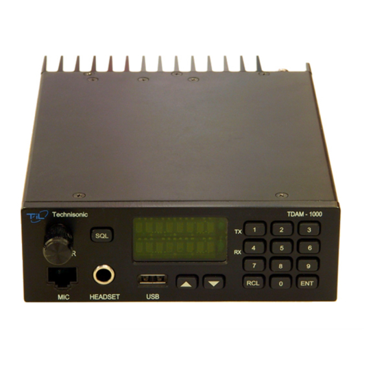
Page 11: Outline Drawing For Model Tdam-1000
TECHNISONIC INDUSTRIES LIMITED FIGURE 1. Outline Drawing for Model TDAM-1000 TMS-110 Installation and Operating Instructions TiL 15RE532 rev. D... -
Page 12: Installation Connections
RS232 Data In Ground SPI CS1 SPI MISO Ground ADC In Cross Mute Out Ground Remote PTT CAN L SPI CS0 SPI MOSI I2C SDA I/O 1 Squelch Out Headset Audio Monitor Audio TMS-110 Installation and Operating Instructions TiL 15RE532 rev. D... -
Page 13: Installation - Wiring Instructions
Squelch signal output. Open collector output which goes to ground when squelch is open. 2.5.11 J3 PINS 1 TO 5, 10, 12, 13, 15 AND 19 TO 23 – BASE STATION INTERFACE For base station applications only. Do not connect. TMS-110 Installation and Operating Instructions TiL 15RE532 rev. D... -
Page 14: Installation - Antenna
The antenna should be at least 52” from any other antenna. The 181299-1 antenna supplied with the TMS-110 system can be assembled by the following procedure: ... - Page 15 Trim the shielding to allow the lock nut to be installed. Install and tighten the antenna base lock nut: Install and tighten the antenna base grounding cap: Place the rubber seal around the antenna base: TMS-110 Installation and Operating Instructions TiL 15RE532 rev. D...
- Page 16 Bend center conductor over into one of the grooves. Cut off excess length: Screw on antenna whip: Route the coax to the back of the radio position. TMS-110 Installation and Operating Instructions TiL 15RE532 rev. D...
-
Page 17: Installation - Bracket
The mic clip can be installed on the radio or elsewhere in the vehicle. There are holes for vertical or horizontal mounting on either side of the radio using the two 6-32 x ¼” screws supplied. TMS-110 Installation and Operating Instructions TiL 15RE532 rev. D... -
Page 18: Installation - Wiring Instructions
Plug the supplied power cord into power jack J1 on the back of the radio and tighten both of the mating screws. Route the red wire to the accessories supply of the vehicle, cutting off any excess. Connect the black wire to the vehicle chassis ground. TMS-110 Installation and Operating Instructions TiL 15RE532 rev. D... -
Page 19: General
‘OFF’. Quick presses of the knob during normal operation will toggle the knob function between volume, channel, squelch and brightness modes. The default mode for the knob is volume when the radio is turned on. TMS-110 Installation and Operating Instructions TiL 15RE532 rev. D... -
Page 20: Normal Operation
For example, to enter 128.75 press: The new frequency is ready to use. The new frequency is not saved in a channel but will remain active until another frequency or channel is selected. TMS-110 Installation and Operating Instructions TiL 15RE532 rev. D... - Page 21 ‘DELETE?’. Press enter again to confirm. For example, to delete channel 48, press: The radio will then tune to the next lower channel number available TMS-110 Installation and Operating Instructions TiL 15RE532 rev. D...
-
Page 22: Function Menu
Enter configuration menu. See 3.6 CONFIGURATION MENU. Read channel or configuration data from USB storage device into radio. Save channel or configuration data to USB storage device from radio. TMS-110 Installation and Operating Instructions TiL 15RE532 rev. D... -
Page 23: Configuration Menu
All replies are transmitted on the frequency of the last channel received. Tx Timer Transmit timer. Selects the transmit timeout timer between Off, 30, 60 or 90 seconds. Table 3. Configuration Menu Commands TMS-110 Installation and Operating Instructions TiL 15RE532 rev. D... -
Page 24: And 8.33 Khz Channel Spacing
118.03333 MHz 8.33 kHz 118.040 118.04166 MHz 8.33 kHz 118.050 118.050 MHz 25 kHz 118.055 118.050 MHz 8.33 kHz 118.060 118.05833 MHz 8.33 kHz Table 4. 25 and 8.33 kHz Channel Spacing TMS-110 Installation and Operating Instructions TiL 15RE532 rev. D... -
Page 25: Dimensions
+/- 1 ppm (0.0001%) Operating Temperature -20 to +55 °C Storage Temperature -40 to +70 °C Power Consumption Transmit High Power < 70 Watts Receive < 15 Watts Standby < 10 Watts TMS-110 Installation and Operating Instructions TiL 15RE532 rev. D... -
Page 26: Receiver Specifications
25 kHz Channel Spacing 300 to 3400 Hz, +1 dB, -2dB 8.33 kHz Channel Spacing 350 to 2500 Hz, +1 dB, -2 dB Audio Distortion < 5% THD Audio Output Power > 10 Watts TMS-110 Installation and Operating Instructions TiL 15RE532 rev. D... -
Page 27: Transmitter Specifications
< 5% @ 90% Modulation Frequency Stability ±1 ppm (0.0001%) Intermodulation Attenuation 40 dB @ 150 kHz Offset Keying Time < 20 ms Release Time < 10 ms Speech Processor 35 dB Dynamic Range TMS-110 Installation and Operating Instructions TiL 15RE532 rev. D... -
Page 28: Warranty
Tel: (905) 890-2113 Fax: (905) 890-5338 IMPORTANT WARRANTY All communication equipment manufactured by Technisonic Industries Limited is warranted to be free of defects in Material or Workmanship under normal use for a period of one year from Date of Purchase by the end user.
Need help?
Do you have a question about the TMS-110 and is the answer not in the manual?
Questions and answers