Keysight Technologies N7015A User Manual
Usb type-c connectivity solution. test fixtures.
Hide thumbs
Also See for N7015A:
- Quick start manual (2 pages) ,
- Quick start and accessories manual (2 pages)
Table of Contents
Advertisement
Advertisement
Table of Contents

Subscribe to Our Youtube Channel
Related Manuals for Keysight Technologies N7015A


Summary of Contents for Keysight Technologies N7015A
- Page 1 Keysight USB Type-C Connectivity Solution (Describes Keysight N7015A / 6A / 7A / 8A Type-C Test Fixtures) User Guide Distributed by: dataTec ▪ Ferdinand-Lassalle-Str. 52 ▪ 72770 Reutlingen ▪ Tel. 07121 / 51 50 50 ▪ Fax 07121 / 51 50 10 ▪ info@datatec.de ▪ www.datatec.de...
- Page 2 Notices © Keysight Technologies 2015-2017 TERMS, THE WARRANTY TERMS IN THE FAR 27.401 or DFAR 227.7103-5 (c), as SEPARATE AGREEMENT WILL CONTROL. applicable in any technical data. 52.227-14 No part of this manual may be reproduced in (June 1987) or DFAR 252.227-7015 (b)(2)
-
Page 3: Table Of Contents
Introduction to the Type-C Test Fixtures Usage Scenarios for the Type-C Test Fixtures How the Type-C Test Fixtures Work Together Type-C Connectivity Test Kits N7015A Type-C High Speed Test Fixture Kit N7018A Type-C Test Controller Kit ZA0200 Type-C Core Connectivity Kit Compatibility with Oscilloscopes For More Information... - Page 4 Probing the CC1, CC2, and VBUS Signals Probing the SBU1 and SBU2 (Secondary Bus) Signals Probing the SBU1 and SBU2 Signals at the N7015A Test Fixture Probing the SBU1 and SBU2 Signals at the N7016A or N7018A Probing the D+ and D- Signals...
- Page 5 If you are Using N7016A Installing the N7016A Type-C Low Speed Signal Access and Control Fixture Software Installing the Appropriate Keysight Compliance Application Software 10 Schematic Diagrams and Pinouts N7015A Dimensions N7015A Pinout N7018A Dimensions N7016A Dimensions N7017A Receptacle Adapter Dimensions...
- Page 6 Contents Keysight USB Type-C Connectivity Solution User Guide...
-
Page 7: Type-C Connectivity Solution Overview
Keysight Type-C Connectivity Solution User Guide Type-C Connectivity Solution Overview Introduction to the Type-C Test Fixtures / 8 Usage Scenarios for the Type-C Test Fixtures / 9 How the Type-C Test Fixtures Work Together / 10 Type-C Connectivity Test Kits / 11 Compatibility with Oscilloscopes / 14 For More Information... -
Page 8: Introduction To The Type-C Test Fixtures
Type-C Connectivity Solution - Overview Introduction to the Type-C Test Fixtures The N7015A, N7016A, N7017A, and N7018A Type-C test fixtures provide a comprehensive and complete testing solution for automated compliance testing, characterization, validation, and debugging of your Type-C host/device including various Type-C interfaces such as USB, DisplayPort, and Thunderbolt . -
Page 9: Usage Scenarios For The Type-C Test Fixtures
Type-C Connectivity Solution - Overview Usage Scenarios for the Type-C Test Fixtures You can use the Type-C test fixtures described in this guide in the following scenarios. • USB 2.0 Tx and Rx testing • USB 3.1 Gen 1 (5Gbs) and Gen 2 (10Gbs) Tx and Rx testing •... -
Page 10: How The Type-C Test Fixtures Work Together
The N7015A test fixture connects to a DUT and a compatible oscilloscope to break out four differential lanes of Type-C high-speed signals from the DUT to the oscilloscope. These high-speed signals can be monitored and analyzed using the Keysight Infiniium software installed on the oscilloscope. -
Page 11: Type-C Connectivity Test Kits
Wrench 8710-2803 N7016A Type-C Low Speed Signal Access and Control Fixture (optional component of the test kit. Can be ordered with the test kit as the N7015A-016 option or separately as a standalone product (model number N7016A) Low Speed Fixture... -
Page 12: N7018A Type-C Test Controller Kit
Quantity Replacement Fuses 2110-0623 N7017A Type-C Receptacle Adapter (optional component of the test kit. Can be ordered with the test kit as the N7015A-017 option or separately as a standalone product (model number N7017A) Receptacle Adapter N7017A N7018A Type-C Test Controller Kit... - Page 13 Type-C Connectivity Solution - Overview Item Part Number Quantity Connector Savers 5061-5311 Blocking Capacitors N9398C 4-slots Low-Profile Modular Power System N6701C Mainframe Source/Measure Unit (power supply/load module) N6786A Keysight Type-C Connectivity Solution User Guide...
-
Page 14: Compatibility With Oscilloscopes
Type-C Connectivity Solution - Overview Compatibility with Oscilloscopes The Type-C test fixtures included in this guide are compatible with the following Keysight oscilloscopes: Compatible Oscilloscopes • Infiniium 90000A Series Oscilloscopes • Infiniium Z-Series Oscilloscopes • Infiniium V-Series Oscilloscopes Compatible Oscilloscope Software Infiniium baseline software version 6.10 or higher Is Your Oscilloscope Software Up-to-Date? Keysight periodically releases software updates to support your probe, fix known defects,... -
Page 15: For More Information
Type-C Connectivity Solution - Overview For More Information... You can find application notes, videos, data sheets, guides, methods of Implementation documents as well as general information about various products that Keysight offers for USB Type-C Interface testing at: http://www.keysight.com/find/type-c Keysight Type-C Connectivity Solution User Guide... - Page 16 Type-C Connectivity Solution - Overview Keysight Type-C Connectivity Solution User Guide...
-
Page 17: N7015A Type-C High Speed Test Fixture
Cleaning the N7015A Test Fixture / 21 The N7015A Type-C high speed test fixture comes with a plug style Type-C connector mated to the receptacle on the USB host/device to enable you to verify and debug USB 3.1 Gen 2 designs, and designs using other high-speed signal standards that support the Type-C connector. -
Page 18: Components
For details, see page Interface to N7016A or N7018A The USB Type-C (plug style) cable that connects the N7015A to the N7018A or N7016A test test fixtures fixture. Through this cable connection, the N7015A passes low-speed power and control signals to these test fixtures. -
Page 19: N7015A Channels Identification Rings
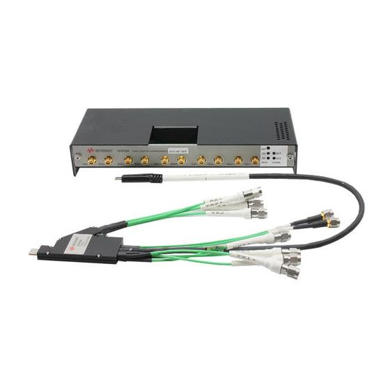
N7015A Type-C Hight Speed Test Fixture N7015A Channels Identification Rings The high-speed Tx and Rx cables and the USB 2.0 cables of the N7015A test fixture have channel identification rings. These rings allow you to color-code each differential lane of Type-C high-speed signals and USB 2.0 signals and thereby easily identify these signals ensuring an error-free... -
Page 20: N7015A Insertion Loss Plot
N7015A Insertion Loss Plot Figure 3 N7015A Fixture Insertion Loss Plot For the insertion loss plot of the N7015A test fixture when used with the N7017A receptacle adapter, refer to the topic “Insertion Loss Plot for N7015A with N7017A" on page 49. -
Page 21: Cleaning The N7015A Test Fixture
N7015A Type-C Hight Speed Test Fixture Cleaning the N7015A Test Fixture The presence of foreign particles on the contacts can degrade the N7015A Type-C connector performance. Therefore, it is recommended that you clean the N7015A Type-C Connector in case there is a suspicion of contamination. - Page 22 N7015A Type-C Hight Speed Test Fixture Keysight Type-C Connectivity Solution User Guide...
-
Page 23: N7018A Type-C Test Controller
Keysight Type-C Connectivity Solution User Guide N7018A Type-C Test Controller Components / 24 Supported ALT Modes / 27 Features / 28 Powering the N7018A and DUT / 30 Pre-use Warnings and Connectivity Precautions / 33 Cleaning the N7018A Test Controller / 34 The N7018A Type-C Test Controller emulates a power delivery link partner to help you validate, characterize, or debug various Type-C host and devices. -
Page 24: Components
N7018A Type-C Test Controller Components SBU1 / SBU2 Probe Points CC Connection Lights Interconnect to N7015A Rx Lines VBUS Status (for LFPS Ping Control ) Lights Interconnect for USB 2.0 signals from N7015A Front View CC1 / CC2 VBUS Probe... - Page 25 N7018A hardware using the N7018A software GUI installed on the oscilloscope / host computer. CC1 / CC2 Probe Points The points to probe the DUT’s CC1 and CC2 signals that the N7015A passes to the N7018A through the USB Type-C cable connection. page 65 to know more.
- Page 26 USB Type-C Connector The USB Type-C connector to connect the N7018A to the N7015A via the USB Type-C plug style cable of the N7015A. Using this connection, the N7015A passes the DUT’s low-speed signals ((VBUS, CC1/2, SBU1/2, GND) to the N7018A for monitoring and full control of the Type-C interface.
-
Page 27: Supported Alt Modes
N7018A Type-C Test Controller Supported ALT Modes The N7018A is capable of operating at and supporting the following ALT modes of the Type-C specifications: • DisplayPort - The following signal configurations are supported. • a two-lane DisplayPort and a two-lane USB 3.1 configuration for simultaneous data and video transfer •... -
Page 28: Features
For these PD negotiations, the N7018A uses the USB Type-C CC line that you selected as the communication channel and manages the connection to the link partner DUT via the Type-C cable connection to the N7015A test fixture. See Also “Power Delivery Contract Setup - Flow of Steps"... - Page 29 • allows DisplayPort AUX channel testing by probing and routing the SBU1/SBU2 (reconfigured as AUX+/AUX-) signals received from the DUT via N7015A. These signals can be routed to a DisplayPort Controller via the DisplayPort controller interface on the N7018A. For Thunderbolt 3 DUT control, the N7018A: •...
-
Page 30: Powering The N7018A And Dut
N7018A Type-C Test Controller Powering the N7018A and DUT Powering the N7018A You can power the N7018A by connecting it to the oscilloscope or the host computer using the supplied USB 2.0 cable. Powering the DUT as a Provider or a Consumer The N7018A can power the DUT when acting as a PD provider or a PD consumer. -
Page 31: Setting Up The Wire Harness For The External Power Supply
N7018A Type-C Test Controller Setting up the Wire Harness for the External Power Supply Make the wires connection between the N6786A module’s SMU connector and N7018A’s external power supply connector as illustrated in the following picture. Keysight Type-C Connectivity Solution User Guide... - Page 32 N7018A Type-C Test Controller While making these wires connection: NOTE - ensure that the signal labels on the N7018A and N6786A are matched correctly as illustrated in the picture on the previous page. While - ensure that the wires used conform to the wire gauge indicated in the picture on the previous page.
-
Page 33: Pre-Use Warnings And Connectivity Precautions
N7018A Type-C Test Controller Pre-use Warnings and Connectivity Precautions With USB Type-C connectors and cables involved in an N7018A and N7015A test setup, it is essential that proper procedures are followed for connecting and disconnecting these Type-C cables from the device/host and N7015A/N7018A test fixtures during testing. For instance, you may experience problems when the system is disconnected with the power supply on and greater than 5V voltage present on the VBUS. -
Page 34: Cleaning The N7018A Test Controller
N7018A Type-C Test Controller Cleaning the N7018A Test Controller Do not try to clean the probe using Isopropyl alcohol as it may leave a residue. To clean the N7018A Disconnect the N7018A from all external devices such as an oscilloscope, any test fixtures, or controllers. -
Page 35: N7016A Type-C Low Speed Test Fixture
Keysight Type-C Connectivity Solution User Guide N7016A Type-C Low Speed Test Fixture Introduction / 36 Features / 37 N7016A Block Diagrams / 38 Powering the N7016A / 43 Replacing the N7016A Fuse / 45 This chapter provides details on the N7016A test fixture. -
Page 36: Introduction
Figure 4 N7016A Low Speed Test Fixture When connecting the N7015A’s TX and RX SMA cables to the N7016A TX and RX SMA ports, NOTE ensure that the labels on these SMA cables and SMA ports match. For instance, connect the TX1+ cable from N7015A to TX1+ SMA port on N7016A. -
Page 37: Features
Keysight power supply can supply and load VBUS and report the value of the current. • Can pass the VBUS and N7015A high speed lanes to its Port 2 to be used by a power delivery controller or other link partner. -
Page 38: N7016A Block Diagrams
N7016A Type-C Low Speed Test Fixture N7016A Block Diagrams Connection Block Diagram Keysight Type-C Connectivity Solution User Guide... -
Page 39: Vbus Control Block Diagram
N7016A Type-C Low Speed Test Fixture VBUS Control Block Diagram SBU Switch Block Diagram Keysight Type-C Connectivity Solution User Guide... -
Page 40: Cc Control Block Diagram
N7016A Type-C Low Speed Test Fixture CC Control Block Diagram Keysight Type-C Connectivity Solution User Guide... -
Page 41: Significance And Values Of Rp, Rd, And Ra Termination Resistors In The Usb Type-C Connector
N7016A Type-C Low Speed Test Fixture Significance and Values of Rp, Rd, and Ra Termination Resistors in the USB Type-C Connector: A downstream facing port (DFP), such as a host computer, exposes pull-up terminations, Rp, on its CC pins (CC1 and CC2). An upstream facing port (UFP), such as a peripheral, exposes pull-down terminations, Rd, on its CC pins. -
Page 42: Control Setup Block Diagram
N7016A Type-C Low Speed Test Fixture Control Setup Block Diagram Keysight Type-C Connectivity Solution User Guide... -
Page 43: Powering The N7016A
The external power supply port of the N7016A is also a power sink port. A power supply connector plug is included in the N7015A/16A Type-C Test Kit for convenience. Port 2 of the N7016A low speed fixture can be used to connect a Type-C... - Page 44 N7016A Type-C Low Speed Test Fixture Figure 5 External Power Supply for Low Speed Fixture Keysight Type-C Connectivity Solution User Guide...
-
Page 45: Replacing The N7016A Fuse
Torx size 10 driver. Figure 6 Cover Screws Pull the cover off the N7016A. Pull the fuse out carefully and replace this fuse with one of the fuses provided in the N7015A/16A Type-C Test Kit. Keysight Type-C Connectivity Solution User Guide... - Page 46 N7016A Type-C Low Speed Test Fixture Figure 7 Fuse Location After replacing the fuse, carefully fit the cover back on the N7016A and tighten the three screws on the back side and the two screws on the front side of the N7016A cover (See Figure 6 page 45).
-
Page 47: N7017A Type-C Receptacle Adapter
Enabling Rx signal validation and calibration when testing receptacle devices The N7017A receptacle adapter provides two receptacle connectors. You can use any of these two connectors to connect to the N7015A test fixture’s plug and the other to connect to a USB device’s plug. - Page 48 While making these connections, ensure that the A1 pin marking displayed on the receptacle adapter is aligned to the A1 pin on the N7015A test fixture as shown in the figure below. To learn more about the pinout of the N7017A’s receptacle connectors, refer to the topic “N7017A...
-
Page 49: Insertion Loss Plot For N7015A With N7017A
N7017A Type-C Receptacle Adapter Insertion Loss Plot for N7015A with N7017A Keysight Type-C Connectivity Solution User Guide... - Page 50 N7017A Type-C Receptacle Adapter Keysight Type-C Connectivity Solution User Guide...
-
Page 51: Recommended Accessories
N2823A or N5448B Coaxial Phase Matched Cable Pair For extending the cable length of the N7015A and to add convenience and flexibility to the probing setup, use the N2823A 39 inches (1 m) long coaxial phase matched cable pair. This coaxial cable has... - Page 52 N5448B Coaxial Cable Pair The figure below shows the N5448B cables attached to the 2.92 mm high speed signal connectors of the N7015A test fixture and channels 1 and 3 of the Infiniium oscilloscope. Keysight Type-C Connectivity Solution User Guide...
- Page 53 The N2823A (or the shorter N5448B) cables provide excellent signal integrity to support high speed digital signals. These are, therefore, optimum for use with the matched cables for differential high speed lines of the N7015A Type-C High Speed Test Fixture’s connectivity with the Infiniium Oscilloscope channels.
-
Page 54: Infiniimax 1130B Series Probe Amplifier
Recommended Accessories The maximum bend radius for the N2823A and N5448B coaxial cable pair is CAUTION 30 mm. Bending these cables at too tight a radius or twisting the cables can cause damage, reduce performance, and impact the precision of these cables. -
Page 55: Sample Setups For Type-C Testing
Keysight Type-C Connectivity Solution User Guide Sample Setups for Type-C Testing Testing a USB 3.1 Host (Tx) / 56 Testing a DisplayPort (2+2) Source (Tx and AUX Channel Testing) / 57 Testing a DisplayPort (4 lanes) Source (Tx and AUX Channel Testing) / 58 Testing a Thunderbolt 3 Host (Tx) / 59 Testing a USB Power Delivery Consumer over Type-C Interface / 60 Testing a USB Power Delivery Provider with N7018A set to Sink Current / 61... -
Page 56: Testing A Usb 3.1 Host (Tx)
Notes for USB 3.1 Testing Setup The Rx SMA cables of N7015A connect to the Tx SMA ports of N7018A only in USB 3.1 setups for LFPS signaling. The TX1/RX1± pair is available for USB 3.1 data transmission if the Type-C connector orientation is selected as Normal (CC1). -
Page 57: Testing A Displayport (2+2) Source (Tx And Aux Channel Testing)
Sample Setups for Type-C Testing Testing a DisplayPort (2+2) Source (Tx and AUX Channel Testing) Notes for DisplayPort 2+2 Lanes Testing Setup A DisplayPort Controller such as Unigraf DPR-100 is mandatory in this setup. The TX1/RX1± pair is available for USB 3.1 data transmission and TX2/RX2± pair is available for DisplayPort transmission if the Type-C connector orientation is selected as Normal (CC1). -
Page 58: Testing A Displayport (4 Lanes) Source (Tx And Aux Channel Testing)
Sample Setups for Type-C Testing Testing a DisplayPort (4 lanes) Source (Tx and AUX Channel Testing) Notes for DisplayPort 4 Lanes Testing Setup A DisplayPort Controller such as Unigraf DPR-100 is mandatory in this setup. Both TX1/RX1± pair and TX2/RX2± pair are available as DisplayPort lanes irrespective of the Type-C connector orientation. Keysight Type-C Connectivity Solution User Guide... -
Page 59: Testing A Thunderbolt 3 Host (Tx)
Sample Setups for Type-C Testing Testing a Thunderbolt 3 Host (Tx) Notes for Thunderbolt 3 Testing Setup A Thunderbolt Controller is mandatory in this setup. Both TX1/RX1± pair and TX2/RX2± pair are available as Thunderbolt lanes irrespective of the Type-C connector orientation. Keysight Type-C Connectivity Solution User Guide... -
Page 60: Testing A Usb Power Delivery Consumer Over Type-C Interface
Sample Setups for Type-C Testing Testing a USB Power Delivery Consumer over Type-C Interface Notes for Power Delivery Consumer Testing Setup To allow the N7018A to act as a PD provider, you must connect the N7018A’s external power source port to an external power supply so that it can meet the power requirements of the DUT and support high-voltage contracts. -
Page 61: Testing A Usb Power Delivery Provider With N7018A Set To Sink Current
Sample Setups for Type-C Testing Testing a USB Power Delivery Provider with N7018A set to Sink Current Notes for Power Delivery Provider Testing Setup (with N7018A set to sink current) To allow the N7018A to act as a PD consumer and sink current, you must connect the N7018A's external power source port to an external power supply. The external power supply must be set to sink mode (negative current) so that it can sink current during the testing of the DUT. -
Page 62: Testing A Usb Power Delivery Provider Over Type-C Interface
Sample Setups for Type-C Testing Testing a USB Power Delivery Provider over Type-C Interface Notes for Power Delivery Provider Testing Setup By default, the N7018A plays the role of a UFP when configured as a PD Consumer. However, you can change this role by configuring the N7018A to initiate data role swap. -
Page 63: Accessing Type-C Signals
Probing the SBU1 and SBU2 (Secondary Bus) Signals / 67 Probing the D+ and D- Signals / 70 This chapter describes how to access and probe various Type-C high-speed and low-speed signals when using the N7015A test fixture with either N7016A or N7017A. -
Page 64: Overview
Signal N7015A N7016A N7018A High-speed Tx and Rx signals High-speed coax cables of High-speed coax cables of N7015A connected to an N7015A connected to the oscilloscope N7016A SMA ports for routing to another DUT connected to N7016A’s Port2. Low-speed signals... -
Page 65: Probing The Cc1, Cc2, And Vbus Signals
Accessing Type-C Signals Probing the CC1, CC2, and VBUS Signals You can probe the CC1, CC2, and VBUS signals either at the N7016A or at the N7018A. You need passive probes such as Keysight N2871A-3A or 10073D/74D general-purpose high impedance passive probe with 10:1 attenuation ratio to probe these signals. Connect the passive probe to the CC1, CC2 and/or VBUS probe points of the N7016A or N7018A as shown in Figure 2... - Page 66 Accessing Type-C Signals Figure 3 Probing the VBUS at the N7018A Keysight Type-C Connectivity Solution User Guide...
-
Page 67: Probing The Sbu1 And Sbu2 (Secondary Bus) Signals
N7016A / N7018A. Probing the SBU1 and SBU2 Signals at the N7015A Test Fixture You can probe the SBU1 and SBU2 signals at the N7015A using the E2678B InfiniiMax differential socket probe head connected to an InfiniiMax probe. - Page 68 Accessing Type-C Signals Figure 5 Top Views of the N7018A and N7016A test fixtures showing the Probe Head connected to the SBU2 and SBU1 Pins Respectively (Single-ended) Probing the SBU1 and SBU2 Signals Differentially For probing the SBU1 and SBU2 signals differentially, connect the E2678B InfiniiMax differential socket probe head and an InfiniiMax probe across both the SBU1 and SBU2 probe pins labeled with the “+”...
- Page 69 Accessing Type-C Signals Figure 7 Top view of the N7018A highlighting the SBU1 and SBU2 probe pins and the + indicators for differential probing Keysight Type-C Connectivity Solution User Guide...
-
Page 70: Probing The D+ And D- Signals
Connect the E2678B InfiniiMax differential socket probe head and an InfiniiMax probe across both the D+ and D- pins on the top side of the N7016A low speed fixture. Connect the D+/D- SMA cables of the N7015A to the D+/D- SMA ports on the front of the N7016A. -
Page 71: Installing And Configuring Software Components For Type-C Testing
Keysight Type-C Connectivity Solution User Guide Installing and Configuring Software Components for Type-C Testing If you are Using N7018A / 72 Installing the N7018A Type-C Test Controller Software / 72 Launching the N7018A Software GUI / 72 Establishing Connectivity between the N7018A Hardware and Software GUI / 74 Setting up the N7018A Emulation Role and ALT Mode and Establishing Connection with DUT / 75 Setting up and Establishing a Power Delivery Contract with DUT / 78 Configuring LFPS Settings (applicable to USB 3.1 testing only) / 82... -
Page 72: If You Are Using N7018A
Installing and Configuring Software Components for Type-C Testing If you are Using N7018A If you are using N7018A in your test setup, you need the following software component to configure and control the N7018A: N7018A Type-C Test Controller Software Installing the N7018A Type-C Test Controller Software Prerequisite •... - Page 73 Installing and Configuring Software Components for Type-C Testing Figure 9 Startup screen of N7018A Software GUI Keysight Type-C Connectivity Solution User Guide...
-
Page 74: Establishing Connectivity Between The N7018A Hardware And Software Gui
Installing and Configuring Software Components for Type-C Testing Establishing Connectivity between the N7018A Hardware and Software GUI As a first step in configuring the N7018A settings through its software GUI, you connect the software GUI to the N7018A hardware. This allows you to control and configure the hardware through this software GUI. -
Page 75: Setting Up The N7018A Emulation Role And Alt Mode And Establishing Connection With Dut
Select the N7018A Type-C Connector Orientation that you want to use in this test configuration. This represents the side of the Type-C connector that will be active at the N7015A test fixture. • Normal (CC1) - Indicates that the CC1 (CC line on the top of the N7018A USB Type-C connector) will be used as the communication channel. - Page 76 For instance, for the “Normal” connector orientation, the N7015A test fixture should be oriented with the Keysight label facing up and the red dot on the cable facing up. This means that the upper side of the N7015A Type-C cable connects to A1 of the N7018A Type-C port.
- Page 77 N7015A and N7018A test setup. In such configurations, this checkbox allows you to bring the SBU lines in the correct orientation by forcing a reversal.
-
Page 78: Setting Up And Establishing A Power Delivery Contract With Dut
All physical connections must be set up before turning on the power supply to avoid CAUTION damage that may result from connecting/disconnecting components with power supply Make sure the Type-C connection and PD contract is broken before connecting CAUTION /disconnecting a Type-C cable between the N7018A/N7015A and DUT. Keysight Type-C Connectivity Solution User Guide... - Page 79 Installing and Configuring Software Components for Type-C Testing The section below describes the fields available in the Power tab. Available Consumer PDOs (DUT) / Available Provider PDOs (DUT) Based on the currently set power role of the N7018A, either Available Consumer PDOs (DUT) or Available Provider PDOs (DUT) section is displayed.
- Page 80 Installing and Configuring Software Components for Type-C Testing • Max Current - If DUT is the consumer, then the maximum current the DUT may need at the given voltage range. If DUT is the provider, then the maximum current the DUT can guarantee to supply at the given voltage range.
- Page 81 Installing and Configuring Software Components for Type-C Testing • Active Provider PDO - This section displays the PDO that the consumer requested from the advertised provider PDOs. • Active Consumer RDO - This section displays the Response Data Object (RDO) that the provider accepted from the advertised consumer PDOs.
-
Page 82: Configuring Lfps Settings (Applicable To Usb 3.1 Testing Only)
LFPS signaling (LFPS Ping, LFPS Warm Reset, or LFPS Polling patterns). By default, none of the transmission lines are enabled. (Ensure that the Rx high-speed cables of N7015A test fixture are connected to the N7018A Tx line(s) that you enabled in this step.) Use the LFPS Ping section to configure and send LFPS Ping bursts to DUT (that is, the transmission of continuous LFPS signal over a period of defined time). - Page 83 Installing and Configuring Software Components for Type-C Testing - N7018A sends out 3 cycles of LFPS with 40ns time period of each cycle. NOTE - N7018A sends an LFPS burst for the total burst time of 120ns. - N7018A can send an LFPS burst repeatedly (1-32) times depending on your selection.
- Page 84 Installing and Configuring Software Components for Type-C Testing a SuperSpeed design (capable of operating at 5Gbps) or a SuperspeedPlus design (capable of operating at 10Gbps), select the appropriate Gen1 or Gen2 radio button. Click the Enable button to send SCD1/2/LBPM patterns to the DUT. The N7018A continues to send these patterns until you send an LFPS Ping or Warm Reset or click the Disable button.
-
Page 85: Viewing The Status Of The N7018A Connection With The Dut
Installing and Configuring Software Components for Type-C Testing Viewing the Status of the N7018A Connection with the DUT The Status bar at the bottom of the N7018A displays the current status of the N7018A connection with the DUT. The information in the Status bar is auto-refreshed at the time interval of NOTE one and a half seconds. - Page 86 Installing and Configuring Software Components for Type-C Testing Keysight Type-C Connectivity Solution User Guide...
-
Page 87: If You Are Using N7016A
Installing and Configuring Software Components for Type-C Testing If you are Using N7016A Installing the N7016A Type-C Low Speed Signal Access and Control Fixture Software Before you Start Make sure that the Microsoft .NET 4.5.2 software is installed on your Infiniium Oscilloscope or personal computer before installing the N7016A USB Type-C Low Speed Signal Access and Control Fixture software. - Page 88 Installing and Configuring Software Components for Type-C Testing Using the N7016A USB Type-C Low Speed Signal Access and Control Fixture Software The N7016A USB Type-C Low Speed Signal Access and Control Fixture software is used to configure the hardware settings of the low speed fixture. To use this software, perform the following procedure. In the Keysight Type C Interconnect Assembly Controller dialog box, click Connect to connect the N7016A low speed fixture to your Infiniium Oscilloscope or personal computer.
- Page 89 Installing and Configuring Software Components for Type-C Testing Keysight Type-C Connectivity Solution User Guide...
- Page 90 Installing and Configuring Software Components for Type-C Testing Select the appropriate hardware configuration option in the Keysight Type C Interconnect Assembly Controller dialog box to configure the N7016A low speed fixture settings. As you configure these hardware settings, the subsequent actions are logged and displayed in the bottom section of the software driver dialog box.
- Page 91 Installing and Configuring Software Components for Type-C Testing Click Write settings to hardware to allow the configured hardware settings to take effect. Keysight Type-C Connectivity Solution User Guide...
-
Page 92: Installing The Appropriate Keysight Compliance Application Software
Installing and Configuring Software Components for Type-C Testing Installing the Appropriate Keysight Compliance Application Software For compliance testing, you need to install the appropriate Keysight compliance application software in addition to the N7018A / N7016A controller software. These applications are integrated with the N7016A as well as N7018A software. Therefore, irrespective of whether you are using N7016A or N7018A, the compliance applications can be easily used. -
Page 93: Schematic Diagrams And Pinouts
Keysight Type-C Connectivity Solution User Guide 10 Schematic Diagrams and Pinouts N7015A Dimensions / 94 N7015A Pinout / 95 N7018A Dimensions / 98 N7017A Receptacle Adapter Dimensions / 100 N7017A Receptacle Adapter Pinout / 101 Signal Routing when using the N7017A Receptacle Adapter / 102... -
Page 94: N7015A Dimensions
Schematic Diagrams and Pinouts N7015A Dimensions Keysight Type-C Connectivity Solution User Guide... -
Page 95: N7015A Pinout
Schematic Diagrams and Pinouts N7015A Pinout The tables that follow provide the pinouts for the connectors of the N7015A test fixture. Pin Details Connector Name SBU1 SBU2 Top Coax/Bottom Coax Connector Name RX2+ RX2- TX2+ TX2- Top Coax/Bottom Coax Connector... - Page 96 Schematic Diagrams and Pinouts J12 (Looking into the Connector) Pin No. Name Name Pin No. SBU1 VBUS VBUS Keysight Type-C Connectivity Solution User Guide...
- Page 97 Schematic Diagrams and Pinouts J13 (Looking into the Connector) Pin No. Name Name Pin No. TX2+ RX2+ TX2- RX2- VBUS VBUS SBU1 SBU2 VBUS VBUS RX1- TX1- RX1+ TX1+ Keysight Type-C Connectivity Solution User Guide...
-
Page 98: N7018A Dimensions
Schematic Diagrams and Pinouts N7018A Dimensions Keysight Type-C Connectivity Solution User Guide... -
Page 99: N7016A Dimensions
Schematic Diagrams and Pinouts N7016A Dimensions Keysight Type-C Connectivity Solution User Guide... -
Page 100: N7017A Receptacle Adapter Dimensions
Schematic Diagrams and Pinouts N7017A Receptacle Adapter Dimensions All dimensions are in Inches. Keysight Type-C Connectivity Solution User Guide... -
Page 101: N7017A Receptacle Adapter Pinout
Schematic Diagrams and Pinouts N7017A Receptacle Adapter Pinout The following figures illustrate the pinouts for the receptacle connectors on the top and bottom of the N7017A receptacle adapter. Keysight Type-C Connectivity Solution User Guide... -
Page 102: Signal Routing When Using The N7017A Receptacle Adapter
Schematic Diagrams and Pinouts Signal Routing when using the N7017A Receptacle Adapter The following illustration shows how a signal is routed from a DUT to the N7015A test fixture when using the N7017A receptacle adapter to connect the DUT and N7015A test fixture. -
Page 103: Downloading The S-Parameter File
11 Downloading the S-parameter File The N7015A has four high speed differential paths from its 2.92 mm connectors to its Type-C plug. To correct for the signal loss of the N7015A test fixture, the N7017A receptacle adapter, and the N2823A coaxial phase-matched cable pair in the de-embedding software such as InfiniiSim, download the S-parameter files from the below-mentioned product pages. - Page 104 Downloading the S-parameter File Keysight Type-C Connectivity Solution User Guide...
-
Page 105: Characteristics And Specifications
Keysight Type-C Connectivity Solution User Guide 12 Characteristics and Specifica- tions Product Weight N7015A Type-C High Speed Test Fixture 110 grams N7016A Type-C Low Speed Test Fixture 320 grams N7017A Type-C Receptacle Adapter 5 grams N7018A Type-C Test Controller 257 grams... - Page 106 Characteristics and Specifications Keysight Type-C Connectivity Solution User Guide...
-
Page 107: Safety And Regulatory Information
Keysight Type-C Connectivity Solution User Guide 13 Safety and Regulatory Information This product has been designed and tested in accordance with accepted industry standards, and has been supplied in a safe condition. The documentation contains information and warnings that must be followed by the user to ensure safe operation and to maintain the product in a safe condition. -
Page 108: Instrument Markings
Safety and Regulatory Information Instrument Markings Marking Description The CE mark is a registered trademark of the European Community. ISM GRP 1-A denotes the instrument is an Industrial Scientific and Medical Group 1 Class A product. ICES/NMB-001 indicates product compliance with the Canadian Interference-Causing Equipment Standard. Notice for the European Community: This product complies with the WEEE Directive (2002/96/EC) marking requirements. -
Page 109: Index
SMA connectors, compliance application software, software, compliance testing, 10, S-parameter, connector orientation, SuperSpeed, N5448B, consumer, 28, N7015A, N7015A kit, N7015A-016, test scenarios, N7015A-017, N7016A, 11, 12, N7017A dimensions, data role, N7017A pinout, data role swap, N7017A receptacle adapter, UFP,... - Page 110 Index Keysight Type-C Connectivity Solution User Guide...
- Page 111 Keysight USB Type-C Connectivity Solution User Guide...
- Page 112 This information is subject to change without notice. © Keysight Technologies 2017 Edition 1, October 2017 N7015-97005 www.keysight.com Distributed by: dataTec ▪ Ferdinand-Lassalle-Str. 52 ▪ 72770 Reutlingen ▪ Tel. 07121 / 51 50 50 ▪ Fax 07121 / 51 50 10 ▪ info@datatec.de ▪ www.datatec.de...
Need help?
Do you have a question about the N7015A and is the answer not in the manual?
Questions and answers