Dell EMC PowerEdge MX740c Installation And Service Manual
Hide thumbs
Also See for PowerEdge MX740c:
- Technical manual (43 pages) ,
- Hardware architecture manual (75 pages)

Related Manuals for Dell EMC PowerEdge MX740c


Summary of Contents for Dell EMC PowerEdge MX740c
- Page 1 Dell EMC PowerEdge MX740c Installation and Service Manual Regulatory Model: E04B Regulatory Type: E04B001...
- Page 2 Notes, cautions, and warnings NOTE: A NOTE indicates important information that helps you make better use of your product. CAUTION: A CAUTION indicates either potential damage to hardware or loss of data and tells you how to avoid the problem. WARNING: A WARNING indicates a potential for property damage, personal injury, or death.
-
Page 3: Table Of Contents
Contents 1 About this document............................7 2 PowerEdge MX740c sled overview........................ 8 Front view of the system..............................9 Inside the system................................10 Locating the Service Tag of your system........................10 System information label..............................11 3 Initial system setup and configuration......................15 Setting up your system.............................. - Page 4 System cover..................................45 Removing the system cover.............................45 Installing system cover.............................. 46 Air shroud..................................47 Removing air shroud..............................47 Installing air shroud..............................48 Drives....................................49 Removing drive blank..............................49 Installing drive blank..............................50 Removing drive carrier............................... 51 Installing drive carrier..............................52 Removing a drive from drive carrier........................53 Installing a drive into drive carrier..........................
- Page 5 Removing the Jumbo PERC card..........................90 Installing the Jumbo PERC card..........................91 Optional Internal dual SD module........................... 92 Removing the IDSDM card............................92 Installing the IDSDM card............................93 Removing a MicroSD card............................94 Installing a MicroSD card............................95 M.2 BOSS module................................96 Removing the M.2 BOSS module..........................
- Page 6 9 Getting help............................... 133 Contacting Dell EMC..............................133 Documentation feedback.............................. 133 Accessing system information by using QRL......................133 Quick Resource Locator for PowerEdge MX740c system.................. 134 Receiving automated support with SupportAssist ....................134 Recycling or End-of-Life service information......................134 10 Documentation resources......................... 135...
-
Page 7: About This Document
The PowerEdge MX740c is compatible with the PowerEdge MX7000 enclosure. For more information about the enclosure, refer to the Installation and Service Manual for the PowerEdge MX7000 at Dell.com/poweredgemanuals. -
Page 8: Poweredge Mx740C Sled Overview
PowerEdge MX740c sled overview The Dell EMCPowerEdge MX740c is a single width compute sled and supports: • Up to two Intel Xeon Scalable processors. • Up to 24 DIMM slots. • Up to six 2.5-inch SAS, SATA (HDD/SSD), or NVMe drives. -
Page 9: Front View Of The System
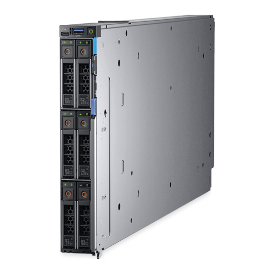
Figure 1. Front view of the 6 drive configuration USB 3.0 port iDRAC direct port Drives Release handle Release handle button Information tag System health and System ID indicator Power button For more information about the ports, see Technical Specifications. PowerEdge MX740c sled overview... -
Page 10: Inside The System
Locating the Service Tag of your system The System Information Tab contains the system's unique Express Service Code and Service Tag. This information is used by Dell EMC to identify system configuration, warranty terms, and to route support calls to the appropriate personnel. A Quick Resource Locator (QRL) label on the System Information Tab links to a web page that shows the exact factory configuration and specific warranty purchased. -
Page 11: System Information Label
Figure 3. Locating Service Tag of your system Information tag Service tag System information label Figure 4. Mechanical overview PowerEdge MX740c sled overview... - Page 12 Figure 5. Memory information PowerEdge MX740c sled overview...
- Page 13 Figure 6. System board Figure 7. Removal of IDSDM and Internal USB memory key(optional) PowerEdge MX740c sled overview...
- Page 14 Figure 8. Removal of BBU module and drive cage Figure 9. Removal of backplane and Mezzanine card Figure 10. Removal of PERC cards and Mini Mezzanine card Figure 11. Removal of Jumbo PERC card PowerEdge MX740c sled overview...
-
Page 15: Initial System Setup And Configuration
Initial system setup and configuration Setting up your system Complete the following steps to set up your system: Unpack the system. Remove the I/O connector cover from the system connectors. CAUTION: While installing the system, ensure that it is properly aligned with the slot on the enclosure to prevent damage to the system connectors. -
Page 16: Log In To Idrac
Ensure that you change the default user name and password after setting up the iDRAC IP address. NOTE: The Intel Quick Assist Technology (QAT) on the Dell EMC PowerEdge MX740c is supported with chipset integration and is enabled through an optional license. The license files are enabled on the sleds through iDRAC. -
Page 17: Downloading Drivers And Firmware
Using iDRAC virtual media Dell.com/idracmanuals Downloading drivers and firmware Dell EMC recommends that you download and install the latest BIOS, drivers, and systems management firmware on your system. Prerequisite Ensure that you clear the web browser cache before downloading the drivers and firmware. -
Page 18: Pre-Operating System Management Applications
Pre-operating system management applications You can manage basic settings and features of a system without booting to the operating system by using the system firmware. Topics: • Options to manage the pre-operating system applications • System Setup • Dell Lifecycle Controller •... -
Page 19: System Setup Details
System Setup details The System Setup Main Menu screen details are explained as follows: Option Description System BIOS Enables you to configure BIOS settings. iDRAC Settings Enables you to configure the iDRAC settings. The iDRAC settings utility is an interface to set up and configure the iDRAC parameters by using UEFI (Unified Extensible Firmware Interface). - Page 20 Option Description Network Settings Specifies options to manage the UEFI network settings and boot protocols. Legacy network settings are managed from the Device Settings menu. Integrated Devices Specifies options to manage integrated device controllers and ports, specifies related features and options. Serial Specifies options to manage the serial ports, its related features and options.
- Page 21 Option Description System Indicates the contact information of the Original Equipment Manufacturer (OEM). Manufacturer Contact Information System CPLD Specifies the current version of the system, complex programmable logic device (CPLD) firmware. Version UEFI Compliance Specifies the UEFI compliance level of the system firmware. Version Memory Settings You can use the Memory Settings screen to view all the memory settings and enable or disable specific memory functions, such as system...
- Page 22 Option Description NOTE: The Fault Resilient Mode option establishes an area of memory that is fault resilient. This mode can be used by an operating system that supports the feature to load critical applications or enables the operating system kernel to maximize system availability. Current State of Specifies the current state of the memory operating mode.
- Page 23 Option Description NVDIMM-N Specifies information on the serial number of the NVDIMM-N. Memory Serial Number NVDIMM-N Enables clearing data on specific NVDIMM-N and results in loss of data on that specific NVDIMM-N. Factory Reset and Secure Erase The Persistent Memory screen details can be found in the NVDIMM-N User Guide at Dell.com/poweredgemanuals. Processor Settings You can use the Processor Settings screen to view the processor settings, and perform specific functions such as enabling virtualization technology, hardware prefetcher, logical processor idling, and opportunistic self-refresh.
- Page 24 Option Description However, if power saving considerations outweigh performance, you might want to reduce the frequency of the CPU communication links. If you do this, you should localize memory and I/O accesses to the nearest NUMA node to minimize the impact to system performance. Virtualization Enables or disables the virtualization technology for the processor.
- Page 25 Option Description Option Description Number of Cores Specifies the number of cores per processor. SATA Settings You can use the SATA Settings screen to view the SATA settings of SATA devices and enable SATA and PCIe NVMe RAID mode on your system.
- Page 26 NVMe Settings The NVMe settings enable you to set the NVMe drives to either RAID mode or Non-RAID mode. NOTE: To configure these drives as RAID drives, click System BIOS Settings > SATA Settings > Embedded SATA Option and enable RAID mode. If not, you must set this field to Non-RAID mode. Viewing NVMe Settings To view the NVMe Settings screen, perform the following steps: Turn on, or restart your system.
- Page 27 On the System BIOS screen, click Boot Settings. Boot Settings details The Boot Settings screen details are explained as follows: Option Description Boot Mode Allows you to configure the Boot Sequence and Enable or Disable the individual boot options. The available options are BIOS and UEFI.
- Page 28 Changing boot order About this task You may have to change the boot order if you want to boot from a USB key or an optical drive. The following instructions may vary if you have selected BIOS for Boot Mode. Steps On the System Setup Main Menu screen, click System BIOS >...
- Page 29 Option Description Table 3. UEFI iSCSI Settings screen details Option Description iSCSI Initiator Name Specifies the name of the iSCSI initiator in IQN format. iSCSI Device1 Enables or disables the iSCSI device. When disabled, a UEFI boot option is created for the iSCSI device automatically.
- Page 30 Option Description Embedded Video Enables or disables the use of Embedded Video Controller as the primary display. When set to Enabled, the Controller Embedded Video Controller will be the primary display even if add-in graphic cards are installed. When set to Disabled, an add-in graphics card will be used as the primary display.
- Page 31 Serial Communication You can use the Serial Communication screen to view the properties of the serial communication port. Viewing Serial Communication To view the Serial Communication screen, perform the following steps: Turn on, or restart your system. Press F2 immediately after you see the following message: F2 = System Setup NOTE: If your operating system begins to load before you press F2, wait for the system to finish booting, and then...
- Page 32 System Profile Settings You can use the System Profile Settings screen to enable specific system performance settings such as power management. Viewing System Profile Settings To view the System Profile Settings screen, perform the following steps: Turn on, or restart your system. Press F2 immediately after you see the following message: F2 = System Setup NOTE:...
- Page 33 Option Description The CPU uses the setting to manipulate the internal behavior of the processor and determines whether to target higher performance or better power savings. This option is set to Balanced Performance by default. Number of Turbo NOTE: If there are two processors installed in the system, you will see an entry for Number of Turbo Boost Enabled Boost Enabled Cores for Processor 2.
- Page 34 Option Description TPM Information NOTE: The TPM menu is available only when the TPM module is installed. Enables you to control the reporting mode of the TPM. The TPM Security option is set to Off by default. You can only modify the TPM Status, and TPM Activation, and the Intel TXT fields if the TPM Status field is set to either On with Pre-boot Measurements or On without Pre-boot Measurements.
- Page 35 Option Description settings, and blocks access to all in-band management tools. All management should be managed through out-of- band. This option is set to Enabled by default. NOTE: BIOS update requires HECI devices to be operational and DUP updates require IPMI interface to be operational.
- Page 36 Steps To enter System Setup, press F2 immediately after turning on or rebooting your system. On the System Setup Main Menu screen, click System BIOS > System Security. On the System Security screen, verify that Password Status is set to Unlocked. In the System Password field, type your system password, and press Enter or Tab.
- Page 37 Operating with setup password enabled If Setup Password is set to Enabled, type the correct setup password before modifying the system setup options. If you do not type the correct password in three attempts, the system displays the following message: Password Invalid.
- Page 38 Option Description Redundant OS NOTE: This option is disabled if Redundant OS Location is set to None. State When set to Visible, the backup disk is visible to the boot list and OS. When set to Hidden, the backup disk is disabled and is not visible to the boot list and OS.
-
Page 39: Idrac Settings Utility
Option Description Dell Wyse P25/P45 Enables or disables the Dell Wyse P25/P45 BIOS Access. This option is set to Enabled by default. BIOS Access Power Cycle Enables or disables the Power Cycle Request. This option is set to None by default. Request iDRAC Settings utility The iDRAC settings utility is an interface to set up and configure the iDRAC parameters by using UEFI. -
Page 40: Boot Manager Main Menu
F11 = Boot Manager If your operating system begins to load before you press F11, allow the system to complete the booting, and then restart your system and try again. Boot Manager main menu Menu item Description Continue Normal The system attempts to boot to devices starting with the first item in the boot order. If the boot attempt fails, the Boot system continues with the next item in the boot order until the boot is successful or no more boot options are found. -
Page 41: Installing And Removing System Components
Installing and removing system components Safety instructions WARNING: Whenever you need to lift the system, get others to assist you. To avoid injury, do not attempt to lift the system by yourself. WARNING: Opening or removing the system cover while the system is powered on may expose you to a risk of electric shock. CAUTION: Do not operate the system without the cover for a duration exceeding five minutes. -
Page 42: Recommended Tools
Torx T15 and T30 screwdrivers • Wrist grounding strap PowerEdge MX740c sled The PowerEdge MX740c sled is a server unit that is installed into the PowerEdge MX7000 enclosure. Removing the sled from enclosure Prerequisites Follow the safety guidelines listed in Safety Instructions. - Page 43 Figure 12. Removing the sled from enclosure Install the I/O connector cover on the sled. CAUTION: To protect the I/O connector pins, install the I/O connector cover every time a sled is removed from the enclosure. Figure 13. Installing the I/O connector cover on sled NOTE: The color of the I/O connector cover may differ.
-
Page 44: Installing The Sled Into Enclosure
CAUTION: If you are permanently removing the sled, install a sled blank promptly. Operating the enclosure without a blank, for an extended time can result in overheating or performance loss. Next step Install the sled or the sled blank into the enclosure. -
Page 45: System Cover
Figure 15. Installing the sled into enclosure Next step Power on the sled. System cover The system cover protects the components inside the system and helps in maintaining air flow inside the system. Removing the system cover Prerequisites Follow the safety guidelines listedin Safety instructions. -
Page 46: Installing System Cover
Figure 16. Removing system cover Next step Replace the system cover. Installing system cover Prerequisites Follow the safety guidelines listed in Safety instructions. Ensure that all internal cables are routed correctly and connected, and no tools or extra parts are left inside the system. Steps Align the tabs on the system cover with the guide slots on the system. -
Page 47: Air Shroud
Figure 17. Installing system cover Next steps Install the sled into the enclosure. Turn on the sled. Air shroud The air shroud aerodynamically directs the airflow across the entire system. The airflow passes air through all the critical parts of the system thus allowing increased cooling preventing overheating. -
Page 48: Installing Air Shroud
Figure 18. Removing air shroud Next step Install the air shroud. Installing air shroud Prerequisites Follow the safety guidelines listed in Safety Instructions. Follow the procedure listed in Before working inside your sled. Steps Align the air shroud with the guide slots on the system. Lower the air shroud into the system until it is firmly seated. -
Page 49: Drives
Figure 19. Installing air shroud Next step Follow the procedure listed in After working inside the sled. Drives Your system supports 2.5-inch SAS/SATA SSD, NVMe drives and PCIe SSDs. The drives or SSDs are supplied in a hot-swappable drive carriers that fit in the drive bays and these drives connect to the system board through the drive backplane. CAUTION: Before attempting to remove or install a drive while the system is running, see the documentation to ensure that the host adapter is configured correctly to support hot-swap drive removal and insertion. -
Page 50: Installing Drive Blank
Figure 20. Removing drive blank Next step Install a drive or a drive blank. Installing drive blank Prerequisite Follow the safety guidelines listed in Safety instructions. CAUTION: Mixing drive blanks from previous generations of PowerEdge servers is not supported. Step Insert the drive blank into the drive slot and push the blank until the release button clicks into place. -
Page 51: Removing Drive Carrier
Figure 21. Installing drive blank Removing drive carrier Prerequisites Follow the safety guidelines listed in Safety instructions. Using the management software, prepare the drive for removal. If the drive is online, the green activity or fault indicator flashes while the drive is turning off. When the drive indicators are off, the drive is ready for removal. -
Page 52: Installing Drive Carrier
Figure 22. Removing drive carrier Next step Replace the drive carrier or a drive blank. Installing drive carrier Prerequisites CAUTION: Before attempting to remove or install a drive while the system is running, see the documentation for the storage controller card to ensure that the host adapter is configured correctly to support drive removal and insertion. CAUTION: Mixing drive carriers from previous generations of PowerEdge servers is not supported. -
Page 53: Removing A Drive From Drive Carrier
Figure 23. Installing drive carrier Removing a drive from drive carrier Prerequisites Follow the safety guidelines listed in Safety instructions. Remove the drive carrier. Steps Using the Phillips #1 screwdriver, remove the screws from the slide rails on the drive carrier. Lift the drive out of the drive carrier. -
Page 54: Installing A Drive Into Drive Carrier
Figure 24. Removing a drive from drive carrier Next step Replace the drive into the drive carrier. Installing a drive into drive carrier Prerequisite Follow the safety guidelines listed in Safety instructions Steps Insert the drive into the drive carrier, with the connector end of the drive towards the back of the carrier. Align the screw holes on the drive with the screw holes on the drive carrier. -
Page 55: Drive Backplane
Figure 25. Installing a drive into drive carrier Drive backplane Depending on the configuration, your system supports: • 2.5 inch (x6) Universal backplane • 2.5 inch (x6) SAS/SATA backplane • 2.5 inch (x4) Universal backplane Figure 26. 6 x 2.5-inch universal backplane AUX 2 cable connector AUX 1 cable connector SAS/SATA connector... -
Page 56: Removing Drive Backplane
Figure 27. 6 x 2.5-inch SAS/SATA backplane Power cable connector SAS/SATA connector Signal cable connector Figure 28. 4 x 2.5-inch universal backplane Signal cable connector AUX 1 cable connector SAS/SATA connector AUX 0 cable connector Power cable connector Removing drive backplane Prerequisites CAUTION: To prevent damage to the drives and the drive backplane, you must remove the drives from the system before... -
Page 57: Installing Drive Backplane
Steps Hold the drive backplane by the edges and lift it upwards to disengage the backplane from the guide pins. Lift the backplane out of the sled. Figure 29. Removing drive backplane Next step Replace the drive backplane. Installing drive backplane Prerequisites Follow the safety guidelines listed in Safety instructions... -
Page 58: Cable Routing
Figure 30. Installing drive backplane Next steps Connect the cables to the backplane connectors. Install the drives. Follow the procedure listed in After working inside the sled. Cable routing Figure 31. Cable routing - 4 x 2.5-inch backplane BBU cabling. Installing and removing system components... - Page 59 Figure 32. Cable routing - 4 x 2.5-inch backplane with internal PERC card Figure 33. Cable routing - 4 x 2.5 PCIe backplane with Jumbo PERC card Installing and removing system components...
- Page 60 Figure 34. Cable routing - 6 x 2.5-inch SAS/SATA backplane with internal PERC card Figure 35. Cable routing - 6 x 2.5-inch SAS/SATA backplane with Jumbo PERC card Installing and removing system components...
- Page 61 Figure 36. Cable routing - 6 x 2.5-inch SAS/SATA backplane SATA cabling Figure 37. Cable routing - 6 x 2.5-inch backplane with internal PERC card Installing and removing system components...
-
Page 62: Drive Cage
Figure 38. Cable routing - 6 x 2.5-inch backplane with Jumbo PERC card Figure 39. Cable routing - 6 x 2.5-inch backplane SATA cabling Drive cage The drive cage contains the drives and the battery backup unit module. Removing the drive cage Prerequisites CAUTION: To prevent damage to the drives and backplane, you must remove the drives from the system before removing the... -
Page 63: Installing The Drive Cage
CAUTION: Temporarily label drives before you remove the drives so that you can replace them in the same slots. NOTE: Observe the routing of the cables on the chassis as you remove them from the system. You must route these cables properly when you replace them to prevent the cables from being pinched or crimped. -
Page 64: Battery Backup Unit
Figure 41. Installing the drive cage Next steps Install the drive backplane. Install the drives. Follow the procedure listed in After working inside your sled. Battery backup unit Removing the battery backup unit Prerequisites Follow the safety guidelines listed in Safety Instructions. -
Page 65: Installing The Battery Backup Unit
Figure 42. Removing the BBU module Next steps Replace the BBU in the cage. Replace the BBU module. Installing the battery backup unit Prerequisites Follow the safety guidelines listed in Safety Instructions. Follow the procedure listed in Before working inside your sled. -
Page 66: Removing The Bbu From The Bbu Cage
Figure 43. Installing the BBU Connect the BBU cables to the connector on the system board. Next steps Follow the procedure listed in the After working inside your sled. Replace the drive carrier or a drive blank. Removing the BBU from the BBU cage Prerequisites Follow the safety guidelines listed in Safety... -
Page 67: Installing The Bbu Into The Bbu Cage
Figure 44. Removing the BBU from the BBU cage Next step Install the BBU into the BBU cage. Installing the BBU into the BBU cage Prerequisite Follow the safety guidelines listed in Safety Instructions. Steps Align and slide the BBU into the BBU cage. Using a Phillips #1 screwdriver, tighten the captive screw to secure the BBU to the BBU cage. -
Page 68: Control Panel
Figure 45. Installing the BBU into the BBU cage Next step Install the BBU module. Control panel The control panel allows you to manually control the inputs to the sled. Removing the control panel Prerequisites Follow the safety guidelines listed in Safety Instructions. -
Page 69: Installing The Control Panel
Figure 46. Removing the control panel Next step Install the control panel. Installing the control panel Prerequisites Follow the safety guidelines listed in Safety Instructions. Follow the procedure listed in Before working inside your sled. Steps Align control panel with the slots on the system and slide it in. Connect the control panel cable to the connector on the system board. -
Page 70: System Memory
• Maximum supported DIMM frequency of the processors The PowerEdge MX740c system contains 24 memory sockets split into two sets of 12 sockets, one set per processor. Each 12-socket set is organized into six channels. Installing and removing system components... - Page 71 Figure 48. System memory layout Memory channels are organized as follows: Table 6. Memory channels Channel Processor 1 Processor 2 Slots A1 and A7 Slots B1 and B7 Slots A2 and A8 Slots B2 and B8 Slots A3 and A9 Slots B3 and B9 Slots A4 and A10 Slots B4 and B10...
-
Page 72: General Memory Module Installation Guidelines
Table 7. Memory population DIMM Type DIMM Ranking Capacity Voltage Operating Frequency (in MT/s) RDIMM 1R / 2R 8 GB, 16 GB, 32 GB 1.2 V 2666 LRDIMM 4R / 8R 64 GB, 128 GB 1.2 V 2666 General memory module installation guidelines To ensure optimal performance of your system, observe the following general guidelines when configuring your system memory. -
Page 73: Nvdimm-N Memory Module Installation Guidelines
• When the DIMM quantity is 4 per processor, the population is slot 1, 2, 4, 5. • When the DIMM quantity is 8 per processor, the population is slot 1, 2, 4, 5, 7, 8, 10, 11. NVDIMM-N memory module installation guidelines The following are the recommended guidelines for installing NVDIMM-N memory modules: •... -
Page 74: Mode-Specific Guidelines
Configuration Description Memory population rules RDIMMs NVDIMM-N Processor1 {A11, 12} Configuration 9 20x 32 GB RDIMMs, 4x Processor1 {A1, 2, 3, 4, 5, 6, 7, 8, NVDIMM-Ns 9, 10} Processor2 {B11, 12} Processor2 {B1, 2, 3, 4, 5, 6, 7, 8, 9, 10} Same for all 12x RDIMM Processor1 {A7, 8, 9}... - Page 75 Memory Operating Mode Description prevent errors from causing an uncorrectable failure. Requires two or more ranks to be populated in each channel. Multi Rank Spare Mode Multi Rank Spare Mode allocates two ranks per channel as a spare. If excessive correctable errors occur in a rank or channel, while the operating system is running, they are moved to the spare area to prevent errors from causing an uncorrectable failure.
- Page 76 Processor Configuration Memory population Memory population information – For 8 DIMMs: A1, A2, A4, A5, A7, A8, A10, Mirror population order {1, 2, 3, 4, 5, 6} {7, 8, 9, 10, Mirroring is supported with 6 or 12 DIMMs per 11, 12} processor.
-
Page 77: Removing A Memory Module
Processor Configuration Memory population Memory population information Fault resilient population Supported with 6 or 12 DIMMs per processor. A{1, 2, 3, 4, 5, 6}, order B{1, 2, 3, 4, 5, 6}, A{7, 8, 9, 10, 11, 12}, B{7, 8, 9, 10, 11, 12} Removing a memory module Prerequisites Follow the safety guidelines listed in... -
Page 78: Installing A Memory Module
Installing a memory module Prerequisites Follow the safety guidelines listed in Safety instructions. CAUTION: To ensure proper system cooling, memory module blanks must be installed in any memory socket that is not occupied. Remove memory module blanks only if you intend to install memory modules in those sockets. NOTE: You must follow the thermal restriction while using DIMM blank. -
Page 79: Processors And Heat Sinks
NOTE: If memory size changes in anyway from the previous successful system boot, the system will prompt the end user during POST that the memory configuration has changed. If the value is incorrect, one or more of the memory modules may not be installed properly. Ensure that the memory module is firmly seated in the memory module socket. -
Page 80: Removing The Processor From The Processor And Heat Sink Module
Figure 51. Removing the processor and heat sink module ( PHM ) Next step Install the processor and heat sink module. Removing the processor from the processor and heat sink module Prerequisites Follow the safety guidelines listed in Safety Instructions. Follow the procedure listed in Before working inside your sled. - Page 81 Figure 52. Loosening the processor bracket Lift the bracket and the processor away from the heat sink, and place the processor connector side down on the processor tray. Flex the outer edges of the bracket to release the bracket from the processor. NOTE: Ensure that the processor and the bracket are placed in the tray after you remove the heat sink.
-
Page 82: Installing The Processor Into A Processor And Heat Sink Module
Installing the processor into a processor and heat sink module Prerequisites Follow the safety guidelines listed in Safety instructions. Follow the procedure listed in the Before working inside the sled. Steps Place the processor in the processor tray. NOTE: Ensure that the pin 1 indicator on the processor tray is aligned with the pin 1 indicator on the processor. Flex the outer edges of the bracket around the processor ensuring that the processor is locked into the clips on the bracket. - Page 83 Figure 55. Applying thermal grease on top of the processor Place the heat sink on the processor and push down on the base of the heat sink until the bracket locks onto the heat sink. NOTE: • Ensure that the two guide pin holes on the bracket match the guide holes on the heat sink. •...
-
Page 84: Installing A Processor And Heat Sink Module
Figure 56. Installing the heat sink onto the processor Next steps Install the processor and heat sink module. Install the air shroud. Follow the procedure listed in After working inside your sled. Installing a processor and heat sink module Prerequisites CAUTION: Never remove the heat sink from a processor unless you intend to replace the processor. -
Page 85: Idrac Card
In the PowerEdge MX740c, iDRAC is not embedded on the system board. The iDRAC is a separate card unlike other 14G PowerEdge servers. The vFlash card for the PowerEdge MX740c is available on the iDRAC card. Removing the iDRAC card... - Page 86 CAUTION: If either the system board or iDRAC card fails, it is required to replace both system board and iDRAC card at the same time. Step Hold the blue pull tag and lift the iDRAC card away from the system. Figure 58.
-
Page 87: Installing The Idrac Card
Installing the iDRAC card Prerequisites CAUTION: To prevent damage to the iDRAC card, you must hold the card only by its edges. Follow the safety guidelines listed in Safety Instructions. Follow the procedure listed in Before working inside the sled. CAUTION: If either the system board or iDRAC card fails, it is required to replace both system board and iDRAC card at the same time. -
Page 88: Perc Card
Figure 61. Installing a vFlash card Next step Follow the procedure listed in After working inside your sled. PERC card Your system includes dedicated slots on the system board for PERC cards. Removing the PERC card Prerequisites Follow the safety guidelines listed in Safety Instructions. -
Page 89: Installing The Perc Card
Figure 62. Removing the PERC card (HBA330) Next step Follow the procedure listed in After working inside your sled. Installing the PERC card Prerequisites Follow the safety guidelines listed in Safety Instructions. Follow the procedure listed in Before working inside the sled. -
Page 90: Removing The Jumbo Perc Card
Figure 63. Installing the PERC card Close the lever on the PERC card. Next steps Connect the cable to the PERC card. Follow the procedure listed in After working inside your sled. Removing the Jumbo PERC card Prerequisites Follow the safety guidelines listed in the Safety instructions. -
Page 91: Installing The Jumbo Perc Card
Figure 64. Removing the Jumbo PERC card NOTE: When Jumbo PERC is installed in the mini Mezzanine slot, you cannot install any other controller cards in the mini Mezzanine slot. NOTE: The Jumbo PERC card controls the internal drives, and the storage sled drives mapped to the storage controller. Next step Install the Jumbo PERC card. -
Page 92: Optional Internal Dual Sd Module
Figure 65. Installing the Jumbo PERC card Next steps Connect the cable on the Jumbo PERC card. Follow the procedure listed in the After working inside your sled. Optional Internal dual SD module The IDSDM module combines the IDSDM features into a single module. NOTE: The write-protect switch is on the IDSDM module. -
Page 93: Installing The Idsdm Card
Figure 66. Removing the IDSDM card Next step Install the IDSDM card. Installing the IDSDM card Prerequisites Follow the safety guidelines listed in Safety Instructions. Follow the procedure listed in Before working inside your sled. CAUTION: To prevent damage to the IDSDM card, you must hold the card only by its edges. Steps Locate the IDSDM card connector on the system board. -
Page 94: Removing A Microsd Card
Figure 67. Installing the IDSDM card Next step Follow the procedure listed in After working inside your sled. Removing a MicroSD card Prerequisites Follow the safety guidelines listed in Safety Instructions. Follow the procedure listed in Before working inside the sled. -
Page 95: Installing A Microsd Card
Figure 68. Removing a MicroSD card Next steps Install a MicroSD card. Follow the procedure listed in After working inside your sled Installing a MicroSD card Prerequisites Follow the safety guidelines listed in Safety Instructions. Follow the procedure listed in Before working inside the sled. -
Page 96: M.2 Boss Module
Figure 69. Installing a MicroSD card Next steps Install the IDSDM card. Follow the procedure listed in After working inside your sled M.2 BOSS module The BOSS card is a simple RAID solution card which supports upto 2 M.2 SATA drives. The BOSS adapter card has a x8 connector using PCIe gen 2.0 x2 lanes, available only in the low-profile and half-height form factor. -
Page 97: Installing The M.2 Boss Module
Figure 70. Removing the M.2 BOSS module Next step Install the M.2 BOSS module. Installing the M.2 BOSS module Prerequisites Follow the safety guidelines listed in Safety instructions. Follow the procedure listed in the Before working inside your sled. Steps Align the M.2 BOSS module connector with the connectors on the system board and the guide on the M.2 BOSS module with the guiding slot on the system board. -
Page 98: Removing The M.2 Boss Card
Figure 71. Installing the M.2 boss module Next step Follow the procedure listed in After working inside your sled. Removing the M.2 BOSS card Prerequisites Follow the safety guidelines listed in the Safety instructions. Follow the procedure listed in the Before working inside your sled. -
Page 99: Installing The M.2 Boss Card
Figure 72. Removing the M.2 BOSS card Next step Install the M.2 BOSS card. Installing the M.2 BOSS card Prerequisites Follow the safety guidelines listed in the Safety instructions. Follow the procedure listed in the Before working inside your sled. Steps Align the M.2 BOSS card at angle of 45 degrees with the SATA connector on the M.2 BOSS module. -
Page 100: Mezzanine Card
Figure 73. Installing the M.2 BOSS card Next steps Install the M.2 BOSS module. Follow the procedure listed in the After working inside your sled. Mezzanine card Your system supports two mezzanine cards: • PCIe mezzanine card slot A supports fabric A. This card must match the fabric type of I/O modules installed in I/O module bays A1. •... -
Page 101: Installing The Mezzanine Card
Figure 74. Removing the Mezzanine card Next steps Install the Mezzanine card. Follow the procedure listed in After working inside your sled. Installing the Mezzanine card Prerequisites Follow the safety guidelines listed in Safety Instructions. Follow the procedure listed in Before working inside the sled. -
Page 102: Removing The Mini Mezzanine Card
Figure 75. Installing the Mezzanine card Next step Follow the procedure listed in After working inside your sled. Removing the mini Mezzanine card Prerequisites CAUTION: To ensure proper system cooling, mini Mezzanine blank must be installed in the mini Mezzanine socket. NOTE: The removal of the blank is recommended only if you intend to install a mini Mezzanine card in this socket. -
Page 103: Installing The Mini Mezzanine Card
Figure 76. Removing the mini Mezzanine card NOTE: Install the connector cap on the I/O connector of the mini Mezzanine card, when not installed on system board. Next step Follow the procedure listed in After working inside your sled. Installing the mini Mezzanine card Prerequisites Follow the safety guidelines listed in Safety... -
Page 104: Removing The Mini Mezzanine Card Blank
Figure 77. Installing the mini Mezzanine card Close the lever on the mini Mezzanine card. Next step Follow the procedure listed in After working inside your sled. Removing the mini Mezzanine card blank Prerequisites CAUTION: To ensure proper system cooling, the mini Mezzanine blank must be installed in the mini Mezzanine socket. NOTE: The removal of the blank is recommended only if you intend to install a mini Mezzanine card in the socket. -
Page 105: Installing The Mini Mezzanine Card Blank
Figure 78. Removing the mini Mezzanine card blank Next step Follow the procedure listed in After working inside your sled. Installing the mini Mezzanine card blank Prerequisites Follow the safety guidelines listed in Safety Instructions. Follow the procedure listed in Before working inside the sled. -
Page 106: Optional Internal Usb Memory Key
Figure 79. Installing the mini Mezzanine card blank Next step Follow the procedure listed in After working inside your sled. Optional internal USB memory key An optional USB memory key installed inside your system can be used as a boot device, security key, or mass storage device. To boot from the USB memory key, configure the USB memory key with a boot image and then specify the USB memory key in the boot sequence in System Setup. -
Page 107: System Battery
Follow the procedure listed in After working inside your sled. System battery The system battery is used for low-level system functions such as powering the real-time and date settings of the system. Replacing the system battery - Option A Prerequisites WARNING: There is a danger of a new battery exploding if it is incorrectly installed. -
Page 108: Replacing The System Battery - Option B
Figure 81. Installing the system battery Next steps Follow the procedure listed in After working inside your sled. Enter the System Setup to confirm that the battery is operating properly. Enter the correct time and date in the System Setup's Time and Date fields. Exit the System Setup. - Page 109 Figure 82. Removing the system battery To install a new system battery: Push the battery lock slightly away. NOTE: Ensure that you do not push the battery holder more that 3.2 millimeters or you might risk damaging the part. b Hold the battery with the + sign facing the positive side of the battery connector. Insert the battery into the battery socket and push the positive side of the battery until the battery snaps into place.
-
Page 110: System Board
Figure 83. Installing the system battery Next steps Follow the procedure listed in After working inside your sled. Enter the System Setup to confirm that the battery is operating properly. Enter the correct time and date in the System Setup's Time and Date fields. Exit the System Setup. - Page 111 CAUTION: You may find the CMOS battery loss or CMOS checksum error displayed during the first instance of powering on the system after the processor or system board replacement which is expected. To fix this, go to setup option to configure the system settings.
-
Page 112: Installing The System Board
Figure 84. Removing the system board Next step Install the system board. Installing the system board Prerequisites Follow the safety guidelines listed in Safety instructions. CAUTION: Do not lift the system board by holding a memory module, processor, or other components. CAUTION: Take care not to damage the system identification button while placing the system board into the system. - Page 113 Figure 85. Installing the system board Lower the system board and install the screws to secure the system board to the system. Next steps Install the following: Internal USB key iDRAC card IDSDM Mini Mezzanine card Mezzanine card(s) PERC card Drive cage Drive backplane Drives...
- Page 114 Follow the procedure listed in After working inside your sled. Ensure that you: Use the Easy Restore feature to restore the Service Tag. For more information, see the Restoring the Service Tag by using the Easy Restore feature section. If the Service Tag is not backed up in the backup flash device, enter the Service Tag manually. For more information, see the Entering the system Service Tag by using System Setup section.
-
Page 115: Trusted Platform Module
Trusted Platform Module Trusted Platform Module (TPM) is a dedicated microprocessor designed to secure hardware by integrating cryptographic keys into devices. Software can use a TPM to authenticate hardware devices. Because each TPM chip has a unique and secret RSA key which is embedded during the manufacture of the TPM, it is capable of performing platform authentication operation. -
Page 116: Initializing Tpm For Bitlocker Users
Figure 86. Installing the TPM Next steps Install the system board. Install the drive backplane. Follow the procedure listed in After working inside your sled. Initializing TPM for BitLocker users Initialize the TPM. For more information, see https://technet.microsoft.com/en-us/library/cc753140.aspx. The TPM Status changes to Enabled, Activated. Initializing the TPM 1.2 for TXT users While booting your system, press F2 to enter System Setup. - Page 117 On the System Setup Main Menu screen, click System BIOS > System Security Settings. Select the TPM Advanced Settings option. From the TPM2 Algorithm Selection option, select SHA256, then go back to System Security Settings screen. On the System Security Settings screen, from the Intel TXT option, select On. Save the settings.
-
Page 118: Jumpers And Connectors
Jumpers and connectors System board jumpers and connectors Figure 87. System board jumpers and connectors Table 11. System board jumpers and connectors Item Connector Description PERC PERC card slot BP_PWR_CONN Backplane power connector Jumpers and connectors... -
Page 119: System Board Jumper Settings
Item Connector Description SATA_CONN SATA connector A1, A2,, A3,, A7,, A8,, A9 DIMMS for CPU1 CPU1 Processor 1 (blank) A4, A5,, A6,, A10,, A11,, A12 DIMMS For CPU1 TPM_MODULE Trusted Platform Module BBU_PWR_CONN BBU power connector BACKPLANE SIGNAL Backplane signal connector Control panel(FIO) connector BATTERY System battery... -
Page 120: Disabling A Forgotten Password
Table 12. System board jumper settings Jumper Setting Description NVRAM_CLR The BIOS configuration settings are retained at system boot. (default) The BIOS configuration settings are cleared at system boot. PWRD_EN The BIOS password feature is enabled. (default) The BIOS password feature is disabled. iDRAC local access is unlocked at next AC power cycle. -
Page 121: Technical Specifications
Video specifications • Environmental specifications System dimensions Figure 88. System dimensions Table 13. System dimensions of thePowerEdge MX740c system System Z (handle closed). Dell EMC PowerEdge MX740c 250.2 mm (9.85 inches) 42.15 mm (1.65 inches) 620.35 mm (24.42 inches) Technical specifications... -
Page 122: System Weight
9.5 kg (20.94 lb) Processor specifications The Dell EMC PowerEdge MX740c system supports up to two Intel Xeon Scalable processors, up to 28 cores per processor. Processor wattage and heat sink dimensions Table 15. Processor wattage and heat sink dimensions... -
Page 123: Memory Specifications
Hard drives The Dell EMC PowerEdge MX740c system supports upto six 2.5-inch, hot-swappable SAS/SATA HDDs, SSDs, or PCIe NVMe drives. The drives are supplied in a hot-swappable drive carriers and these drives connect to the system board or RAID controller through the backplane. -
Page 124: Usb Ports
It is recommended to use Dell branded MicroSD cards associated with the IDSDM configured systems. Micro SD vFlash connector The Dell EMC PowerEdge MX740c system supports one dedicated micro SD card on iDRAC module for future vFlash support. It is recommended to use Dell branded MicroSD card associated with the iDRAC module. -
Page 125: Particulate And Gaseous Contamination Specifications
Temperature Specifications Maximum temperature gradient (operating and storage) 20°C/h (68°F/h) Table 19. Relative humidity specifications Relative humidity Specifications Storage 5% to 95% RH with 33°C (91°F) maximum dew point. Atmosphere must be noncondensing always. Operating 10% to 80% relative humidity with 29°C (84.2°F) maximum dew point. Table 20. -
Page 126: Standard Operating Temperature
Table 24. Particulate contamination specifications Particulate contamination Specifications Air filtration Data center air filtration as defined by ISO Class 8 per ISO 14644-1 with a 95% upper confidence limit. NOTE: This condition applies to data center environments only. Air filtration requirements do not apply to IT equipment designed to be used outside a data center, in environments such as an office or factory floor. -
Page 127: Expanded Operating Temperature
All fans which cool the MX740c are contained in the MX7000 chassis. Thermal management of PowerEdge MX740c delivers high performance for the right amount of cooling to components at the lowest fan speeds across a wide range of ambient temperatures from 10°C to 35°C (50°F to 95°F) and to extended ambient temperature ranges (see Environmental Specifications section). - Page 128 Table 28. Thermal restriction matrix Ambient Support 25 ° C 30 ° C 35 ° C 40 ° C ~ 45 ° C Expanded Operating Temperature No restriction No restriction No restriction (The Does not support CPU recommended operating with TDP > 140W No temperature for Support: Gold 6146 Gold processors with Thermal...
-
Page 129: System Diagnostics And Indicator Codes
System diagnostics and indicator codes The diagnostic indicators on the system front panel display system status during system startup. Topics: • Power button LED • Drive indicator codes • System health and system ID indicator codes • Using system diagnostics Power button LED The power button LED is located on the front panel of your system. -
Page 130: Drive Indicator Codes
Drive indicator codes The LEDs on the drive carrier indicates the state of each drive. Each drive carrier in your system has two LEDs: an activity LED (green) and a status LED (bicolor, green/amber). The activity LED flashes whenever the drive is accessed. Figure 90. -
Page 131: System Health And System Id Indicator Codes
System health and system ID indicator codes The system health and system ID indicator is located on the left control panel of your system. Figure 91. System health and system ID indicators Table 31. System health and system ID indicator codes System health and system ID indicator code Condition Solid blue... - Page 132 Running the Embedded System Diagnostics from Boot Manager Run the Embedded System Diagnostics (ePSA) if your system does not boot. When the system is booting, press F11. Use the up arrow and down arrow keys to select System Utilities > Launch Diagnostics. Alternatively, when the system is booting, press F10, select Hardware Diagnostics >...
-
Page 133: Getting Help
The Contact Technical Support page is displayed with details to call, chat, or e-mail the Dell EMC Global Technical Support team. Documentation feedback You can rate the documentation or write your feedback on any of our Dell EMC documentation pages and click Send Feedback to send your feedback. Accessing system information by using QRL You can use the Quick Resource Locator (QRL) located on the information tag in the front of the MX740c, to access the information about the Dell EMC PowerEdge MX740c. -
Page 134: Quick Resource Locator For Poweredge Mx740C System
Receiving automated support with SupportAssist Dell EMC SupportAssist is an optional Dell EMC Services offering that automates technical support for your Dell EMC server, storage, and networking devices. By installing and setting up a SupportAssist application in your IT environment, you can receive the following benefits: •... -
Page 135: Documentation Resources
To view the document that is listed in the documentation resources table: • From the Dell EMC support site: Click the documentation link that is provided in the Location column in the table. Click the required product or product version. - Page 136 Dell OpenManage Essentials, see Essentials the Dell OpenManage Essentials User’s Guide. For information about installing and using Dell Dell.com/serviceabilitytools SupportAssist, see the Dell EMC SupportAssist Enterprise User’s Guide. For information about partner programs enterprise Dell.com/openmanagemanuals systems management, see the OpenManage Connections Enterprise Systems Management documents.
Need help?
Do you have a question about the PowerEdge MX740c and is the answer not in the manual?
Questions and answers