Milltronics MiniRanger Plus Instruction Manual
Hide thumbs
Also See for MiniRanger Plus:
- Instruction manual (77 pages) ,
- Instruction manual (72 pages)

Related Manuals for Milltronics MiniRanger Plus


Summary of Contents for Milltronics MiniRanger Plus
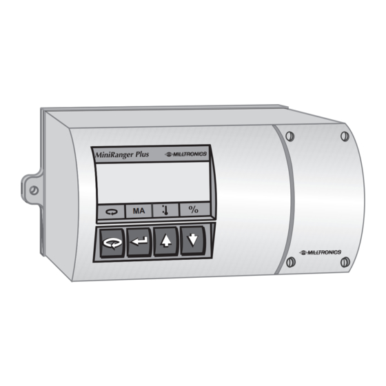
- Page 1 MiniRanger Plus Instruction Manual PL-447 October 1997 33454470 Technology based. Customer driven.
- Page 2 Milltronics has been designing and manufacturing process equipment since 1954. Our fields of expertise include ultrasonic level measurement, in-line weighing of dry bulk solids and motion sensing.
-
Page 3: Table Of Contents
Table of Contents General Information About This Manual About MiniRanger Plus Specifications MiniRanger Plus Transducer Installation Dimensions Interconnection Transducer Synchronization Current Output Relay Output Power ComVerter Start Up General Display & Keypad Run Mode Program Mode Setting Up Display Messages... - Page 4 Functional Transceiver Transducer Temperature Sound Velocity Blanking Loss of Echo Relays General Functions Alarm Pump Setpoints Status Programming Analog Output Run/Program Applications Simple Level Application Pump Control Application High Level Switch Applications with Standpipe Parameter Description Parameters Troubleshooting Appendices Alphabetical Parameter Listing Programming Chart PL-447...
- Page 5 ABOUT THIS MANUAL It is essential that this manual be referred to for proper installation and operation of your MiniRanger Plus. As MiniRanger Plus requires an STH or Echomax ultrasonic transducer to make a working system, refer to the associated transducer manual as well.
- Page 6 Remotely coupled to an appropriate transducer, MiniRanger Plus is well suited for short to medium range measurements of liquids or solids, in open or closed vessels. MiniRanger Plus is at home in a wide variety of industries: food, pharmaceutical, chemical, water, waste water - to name a few.
- Page 7 SPECIFICATIONS MINIRANGER PLUS » 100 / 115 / 200 / 230 V ±15%, switch selectable Power: » 50 / 60 Hz, 15 VA Range: » solids applications: 5 m (transducer dependent) » liquid applications: 10 m (transducer dependent) Accuracy: » 0.25% of range or 6 mm (0.24"), whichever is greater Resolution: »...
- Page 8 ⊗ PL-447...
- Page 9 INSTALLATION This product is susceptible to electrostatic shock. Follow proper grounding procedures. DIMENSIONS 270 mm (10.6") 254 mm (10") 138 mm (5.4") 69 mm (2.7") integral junction box terminal sealed enclosure (cover removed) block with terminal block and layout voltage selection switch Conduit entry location.
-
Page 10: Transducer
SYNCHRONIZATION In applications where more than one MiniRanger Plus, to a maximum of 8, are going to be used or where their transducers are sharing a common conduit, synchronization is required. When synchronized, no device transmits within 180 ms of the prior one(s). -
Page 11: Current Output
CURRENT OUTPUT to customer instrumentation isolated mA output, 750 Ω max load RELAY OUTPUT n.c. relays shown in n.o. de-energized state, contacts rated 5 A at n.c. 230 V non-inductive n.o. All relays are certified for use in equipment where the short circuit capacity of the circuits in which they are connected is limited by fuses having ratings not exceeding the rating of the relays. -
Page 12: Power
POWER VOLTAGE SELECT customer voltage supply COMVERTER Optional Dolphin Interface ComVerter MiniRanger Plus Refer to Dolphin instruction manual for interconnection details. PL-447... - Page 13 ⊗ PL-447...
- Page 14 ⊗ PL-447...
- Page 15 START UP GENERAL The MiniRanger Plus has two modes of operation: run and program . When the unit is powered, after installation procedures have been completed, it is programmed to start up in the run mode, to detect the distance from the transducer face to the target in meters.
-
Page 16: Run Mode
DISPLAY and KEYPAD Keypad Run Mode reading units high alarm indicators : = high, = high - high process material level rising or falling bar graph representation of material level, 0 to 100% of span low alarm indicators : = low, = low - low reading questionable, appears during fail-safe operation auxiliary reading... -
Page 17: Program Mode
Program Mode parameter type ( transducer, relay, or mA output ) reading units ‘change value’ accessed Keypad alternates program access scroll scroll mode between down ‘select parameter’ mode and ‘change value’ functions PL-447... - Page 18 SETTING UP To Access Program: run display program starts at P001 To Select a Parameter : PL-447...
- Page 19 To Change a Parameter Value : select parameter, e.g. P001 = 3 initiate change function Security Must Be Disabled! increase or decrease to the desired value. if no response, security not disabled! save and return to ‘select parameter’ function, Must Be Pressed to e.g.
- Page 20 Express : Parameter to jump back to P001 Value to jump to the factory setting e.g. P999 jump back to P001 To Return to Run Mode from the program mode e.g. P001 exit and return to run mode PL-447...
- Page 21 DISPLAY MESSAGES ‘OPEN’ in transducer circuit. Refer to Troubleshooting. ‘Short’ in transducer circuit or wiring reversed. Refer to Troubleshooting. PL-447...
- Page 22 ⊗ PL-447...
-
Page 23: Functional
FUNCTIONAL TRANSCEIVER The MiniRanger Plus transceiver operates under 1 of 5 sets of preset conditions (P003), summarized as follows: parameter measurement echo filter fail-safe long value response verification timer pulses* 0.1 m/min slow 1 m/min 10 m/min 100 m/min 1000 m/min fast *each measurement consists of one short pulse plus the set number of long pulses. -
Page 24: Temperature
SOUND VELOCITY The MiniRanger Plus can be calibrated to compensate for sound velocity error in fixed temperature, homogenous atmospheres. The basis is to physically measure the level (measuring tape or sight glass) and enter the value via P651. -
Page 25: Loss Of Echo
Relay operation responds, as programmed, to the default level as though an actual material reading. RELAYS GENERAL Two onboard relays are provided in the MiniRanger Plus. Each relay can be assigned one out of three functions. FUNCTIONS Alarm: high alarm : occurs when the level rises to the on setpoint. -
Page 26: Pump
2 during the first pump cycle. During the second cycle, pump 2 responds to relay 1 and pump 1 responds to relay 2. Relays programmed for pump control will not energize within 10 seconds of a MiniRanger Plus power up, or within 10 seconds of each other. SETPOINTS Relay setpoints are in the units as programmed (P005). -
Page 27: Status
STATUS Programming Upon entering the program mode, the alarm relays hold their prior status, pump relays are held off. Relay programming: - select relay & function (P111) - enter setpoints (P112 & P113) • • • relay 1 function e.g. 0 = off relay 2 function e.g. -
Page 28: Run
relay status, relay 1 status, relay 2 relay operational, e.g. relay 2 alarm / pump on, e.g. relay 1 Fail-safe When the fail-safe timer (P070) expires, the relays respond as follows * : Fail-Safe Status Mode (P071) high alarm low alarm pump down pump up high... - Page 29 ANALOG OUTPUT The MiniRanger Plus can be programmed to provide an analog output (P200) of 0 to 20 or 4 to 20 mA, and for proportional or inverse span. Programming Upon entering the Program mode, the analog output level holds its prior value.
- Page 30 RUN / PROGRAM When the MiniRanger Plus changes from run to program, the transceiver stops operating and the last measurement is stored; the associated reading, alarm status and mA output are held (pump control relays are turned off). As a courtesy, the unit reverts to the parameter last addressed during the previous program session.
- Page 31 ⊗ PL-447...
- Page 32 ⊗ PL-447...
- Page 33 APPLICATIONS This section highlights the most common applications to which the MiniRanger Plus is likely to be applied. Other applications not described here, such as position monitoring of a piston on a wood pulverizer, are basically improvisational and imaginative ways of applying the MiniRanger Plus.
- Page 34 A high alarm is required at 4 m from the bottom and a low alarm is required at 1 m from the bottom. The maximum rate of filling or emptying is about 1 m/min. In the event of a loss of echo, the MiniRanger Plus is to go into fail-safe low after 2 min. relay 1...
- Page 35 P003 enter ‘2’ measurement response = 1 m/min. P004 enter ‘102’ the transducer model purchased with this system is an XPS-10 P005 enter ‘1’ units = metres P006 enter ‘5’ empty distance = 5 m P007 enter ‘4.5’ span = 4.5 m P070 enter ‘2’...
- Page 36 Two pumps are to be controlled by the MiniRanger Plus in lead / lag fashion. The first pump to start at 1 m and the second pump to start at 2 m. Both pumps are to stop at 0.25 m.
- Page 37 P003 enter ‘2’ measurement response = 1 m / min note: the associated preset fail-safe timer is 10 minutes. Override this value by setting P070. P004 enter ‘102’ the transducer model purchased with this system is an XPS-10 P005 enter ‘1’ units = metres P006 enter ‘3.6’...
- Page 38 HIGH LEVEL SWITCH The MiniRanger Plus can be programmed as a high level switch. Significant differences between this and other modes of operation are : - the fail-safe function (P070 and P071) is effectively disabled - on loss of echo, the measurement immediately defaults...
- Page 39 P003 enter ‘2’ measurement response = 1 m/min note: this is the next fastest response rate that would satisfy the given maximum filling rate P004 enter ‘104’ the transducer model purchased with this system is an XPS-15 P005 enter ‘1’ units = metres P006 enter ‘4’...
- Page 40 In many liquid applications, access to the vessel must be made via a standpipe. In such cases, Milltronics can provide optional flanged transducers, or split flanges that mate to a flanged standpipe. Another option is to hang the transducer from a blind flange.
- Page 41 ⊗ PL-447...
- Page 42 ⊗ PL-447...
- Page 43 PARAMETER DESCRIPTION P000 lock Locks out the programming ’change value’ function such that the values of P001 through P999 cannot be changed. This however does not prevent the ‘select’ function from use for viewing values. Programming is locked out if the value of P000 is other than 1954. entry : 1954 = unlocked 1954 = locked P001...
- Page 44 If MiniRanger Plus cannot keep up with the rate of level change, select a faster rate. If the reading bounces around an average value, select a slower rate.
- Page 45 P005 units Determines the units for programming and measurement. entry : 1 = metres 2 = centimetres 3 = millimetres 4 = feet 5 = inches P006 empty Distance from transducer face to empty level or maximum target range. P007 span Distance from empty (P006) to full / 100% level or minimum...
- Page 46 3 = 20 to 0 mA 4 = 20 to 4 mA P300 temperature, transducer max The maximum temperature encountered by the integral (transducer) temperature sensor. P341 run time View the accumulated number of days the MiniRanger Plus has been operating. PL-447...
- Page 47 (to access change function). - scroll the value to the actual level, space or distance respective to the mode of measurement (P001). (to validate entry). The MiniRanger Plus calculates the measurement offset to be applied to the reading. P651 sound velocity calibration Provides sound velocity compensation on an empty tank.
- Page 48 P800 near blanking Sets the amount of blanking as measured from the transducer face and extending into the measurement range. Refer to Functional\Blanking. enter value referenced from the face of the transducer in units of P005. P801 range extension Sets the amount of range extension as measured from the empty distance (P006) and extending into the far end blanking.
- Page 49 P806 echo strength The absolute strength of the selected echo, in dB above 1 uV rms. run mode : P807 noise The peak and average ambient noise, in dB above 1 uV rms. Ambient noise includes acoustical and electrical noise being picked up by the transducer / receiver circuit while in the program mode (transmit disabled).
- Page 50 Tests the memory. Test is initiated by scrolling to the parameter or repeated by display : PASS = normal FAIL = consult Milltronics P907 programmer interface Tests the infrared communication link. Test is initiated by scrolling to the parameter or repeated by...
- Page 51 P923 distance measurement The reading corresponding to the distance between the material level and the transducer face. run mode P999 master reset Resets parameters to their factory setting. PL-447...
- Page 52 ⊗ PL-447...
- Page 53 TROUBLESHOOTING The following is a list of operating symptoms, their probable causes and the actions needed to resolve them. SYMPTOM CAUSE ACTION Loss of echo display reads ‘Short’, short circuit or check transducer wiring* no pulsing is felt on the reverse wiring transducer face defective transducer...
- Page 54 - physical damage inspect - excessive foam on liquid face use foam deflector or stilling well or relocate Reading does not change, MiniRanger Plus re-aim transducer* but the level does processing wrong echo, i.e. vessel wall, structural check standpipe for member, stationary...
- Page 55 SYMPTOM CAUSE ACTION Reading erratic echo confidence weak, refer to P805,P807 liquid surface agitated, decrease measurement response P003 enable filter, echo verification material filling relocate transducer* electrical noise check P-807 under quiescent conditions, noise should be under 15 dB transducer cable must be in grounded metal conduit and cable grounded only at TB-1*...
- Page 56 ⊗ PL-447...
- Page 57 APPENDICES Alphabetical Parameter List algorithm P820 submergence transducer P802 confidence threshold P804 temperature fixed P661 distance measurement P923 temperature, transducer max P300 echo confidence P805 transducer P004 echo strength P806 TVT type P830 empty P006 units P005 fail-safe material level P071 fail-safe timer P070...
- Page 58 PROGRAMMING CHART PARAMETER NAME VALUE P001 Operation P002 Material P003 Measurement Response P004 Transducer P005 Units P006 Empty P007 Span P070 Fail-safe Timer P071 Fail-safe Material Level P111-1 Relay Function P111-2 Relay Function P112-1 Relay A Setpoint P112-2 Relay A Setpoint P113-1 Relay B Setpoint P113-2...
Need help?
Do you have a question about the MiniRanger Plus and is the answer not in the manual?
Questions and answers